07. Computer Controlled Machining
Summary
This week was focused on learning how to operate a CNC machine to carve large parts intended for an assembly. The design I went for was a coat rack comprised of three parts, since I wanted to make something simple but big.
The machines we used were CNC routers, the material we used was plywood and the cuttig tool was a 1/4" end mill. For this week's group assignment, we went through our lab's safety training, as well as testing runout, alignment, fixturing, speeds, feeds, materials, and toolpaths for our machine.
1. CNC Milling
Computer Numerical Control milling is a subtractive manufacturing process that removes material from a workpiece using rotating cutting tools. The CNC mill follows programmed toolpaths to carve out precise shapes in metals, plastics, wood, and composites.
The process involves the following steps:
- Part Design - We design a CAD model in our software of choice, we have to take into consideration the geometry of our parts, my design will only require two dimensional toolpaths.
- CAM Software - After finishing our model, we have to convert it into Computer Aided Manufacturing instructions, which will define how the machine will move and cut the material.
- CNC Machine Setup - We secure our material on the machine bed, install the correct tool, and establish a point of origin for the carving process.
- Program Execution - The CNC controller reads the G-code and moves the cutting tool along the programmed paths, our router moves in three axes, X, Y and Z, shaping the material precisely.
- Post Processing & Finishing - Once cutting is complete, the part is removed, cleaned and sometimes subjected to Additional processes like sanding, polishing, or painting to refine the surface.
2. Design
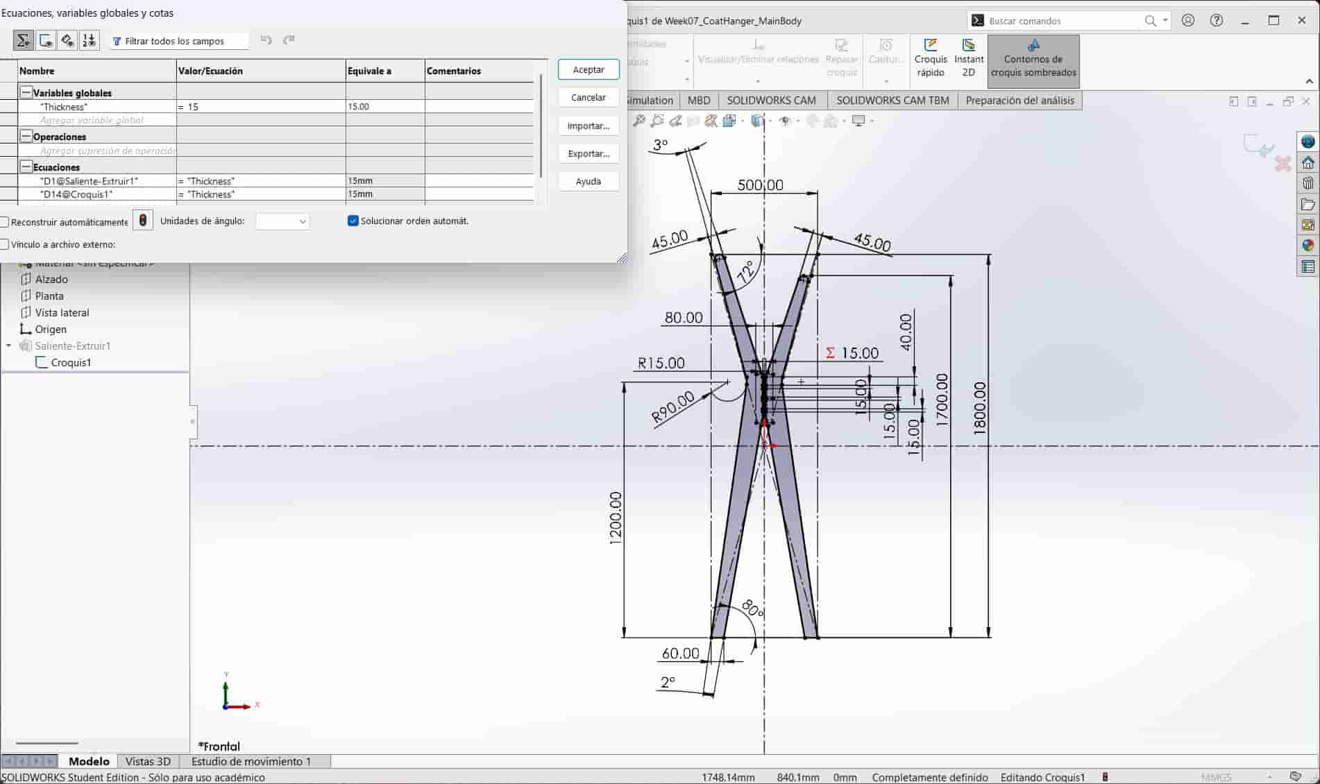
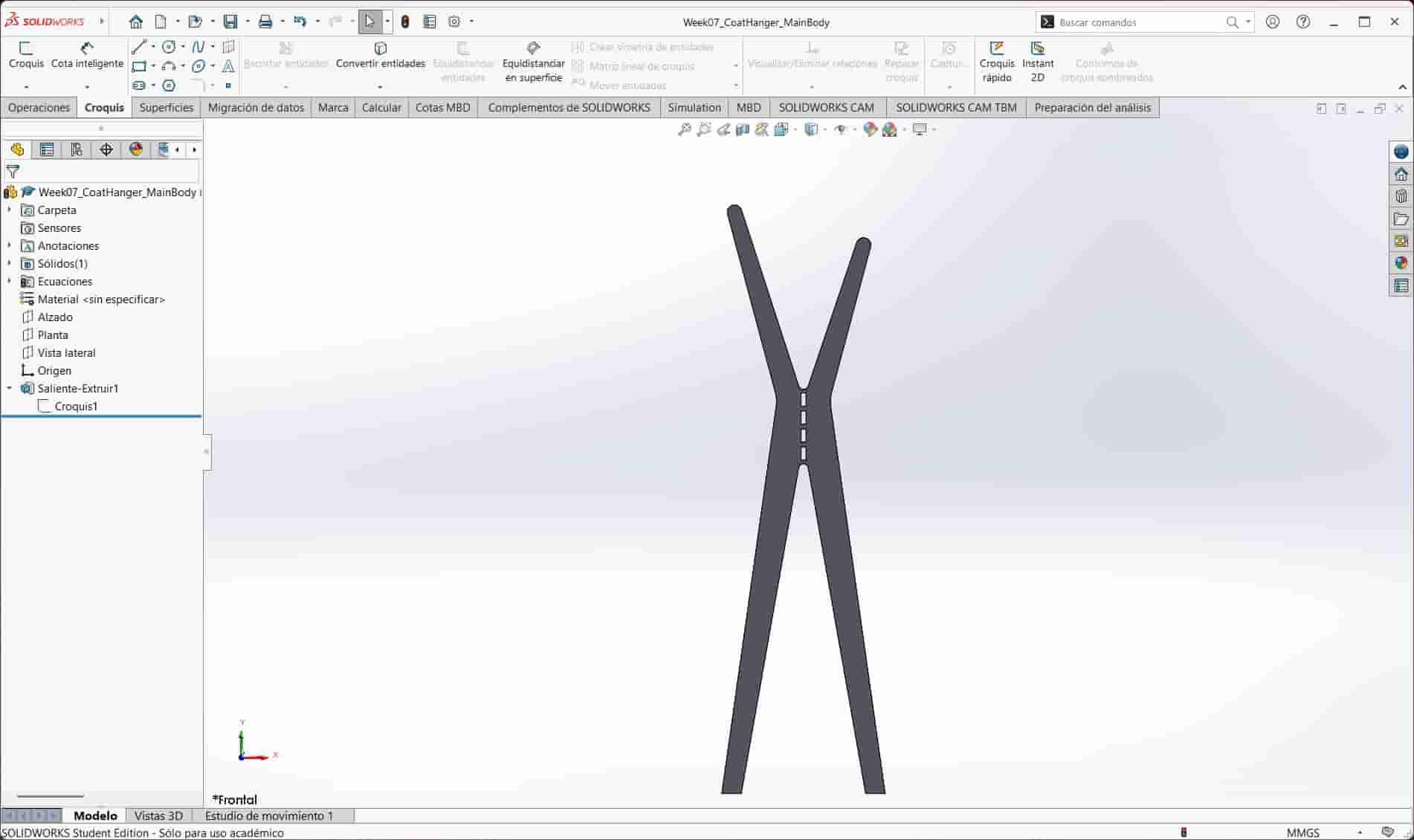
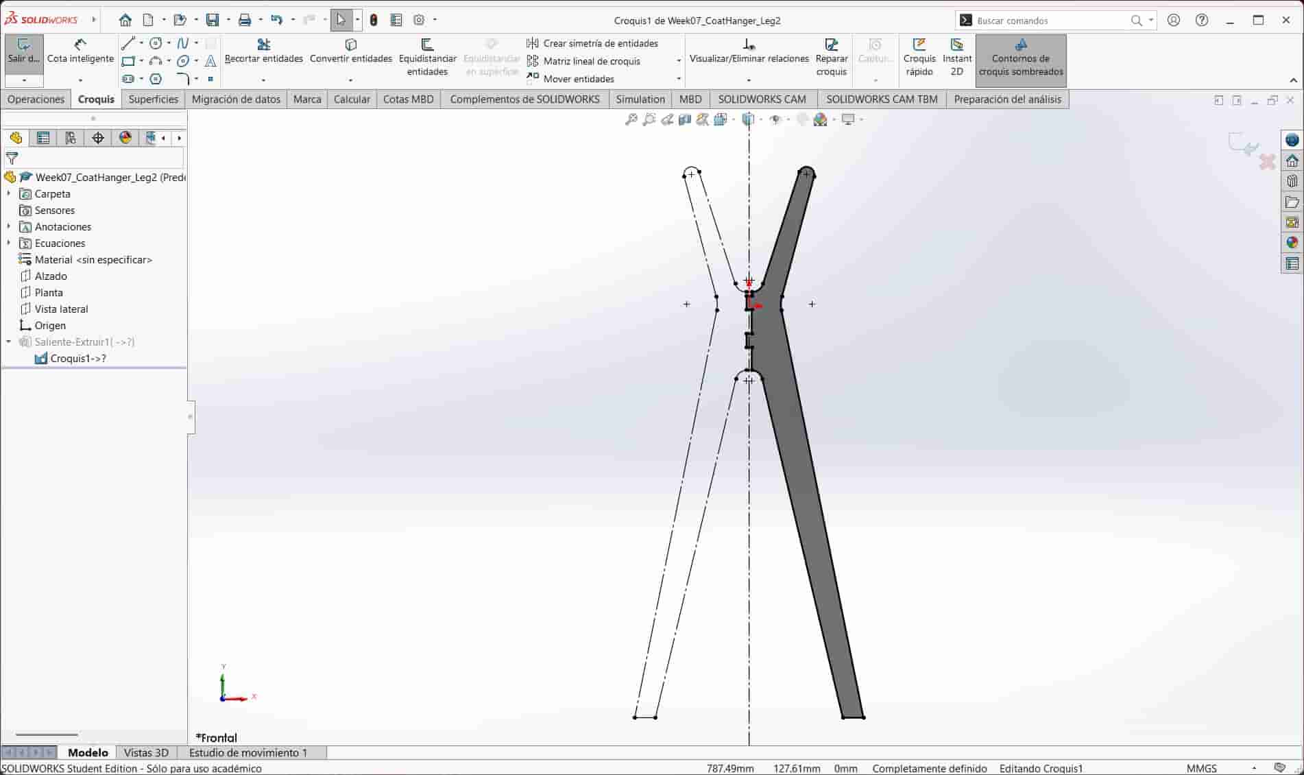
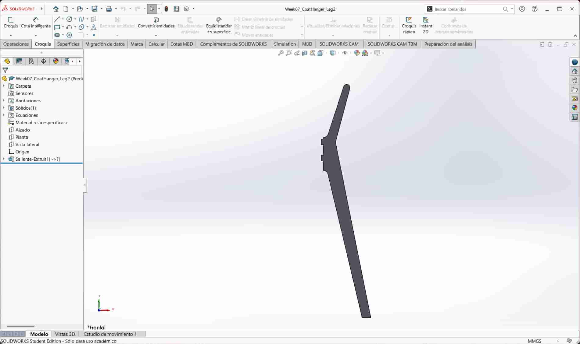
As explained, we begin with a CAD model. My coat rack is comprised of three individual parts that are joined together with simple mortise and tenon joints. I went for a modern aesthetic, using curves and an angled four legged structure.
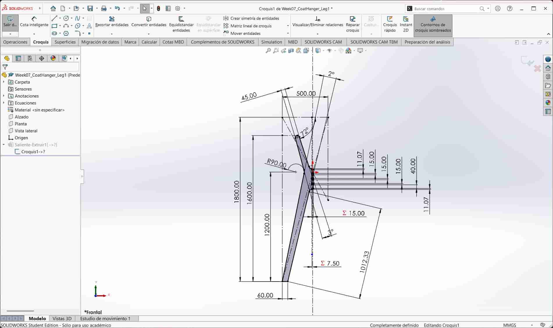
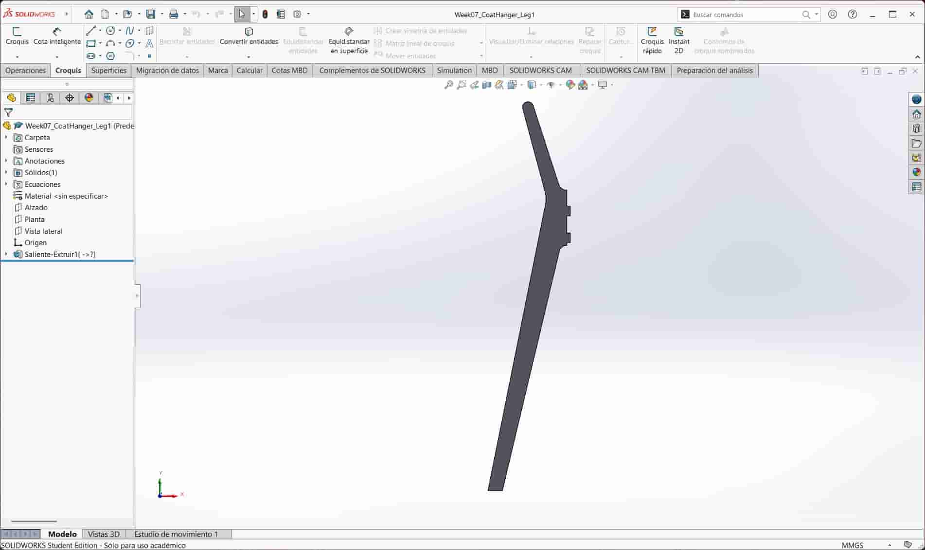
I used the dimentions of the main structure as reference for the legs, which are nearly identical with the only exception being the positioning of the joints.
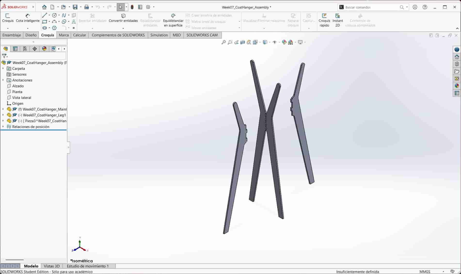
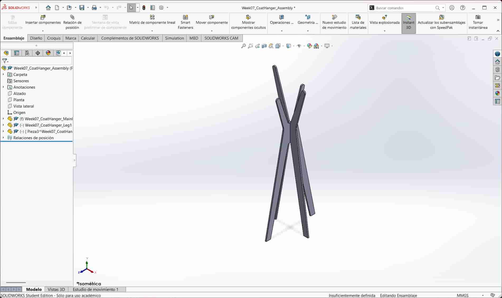
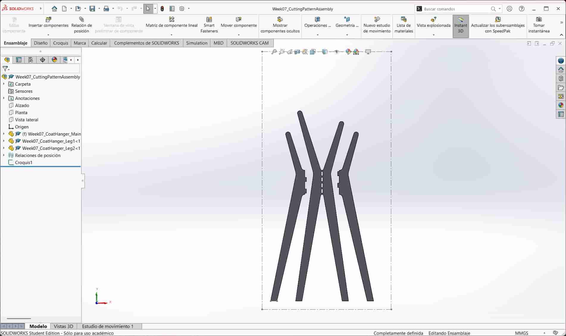
To verify that the parts fit together, I created an assembly in SolidWorks to simulate the assembled rack, which worked as intended.
Since our toolpath will cut all of our parts from a front view, I created an additional assembly where I arranged the parts to be placed at the same height and with the intended faces facing toward us. I then exported this view of the assembly as a DXF file.
3. CAM Software
We will be using the CAM Software to turn our DXF file into the necessary instructions for our machine. There are a variety of CAM software that we can use, I will be using VCarve, which is a piece of software developed by Vectric, commonly used for CNC routing, engraving, and sign making.
To effectively use VCarve I followed the following steps:
3.1 New Project
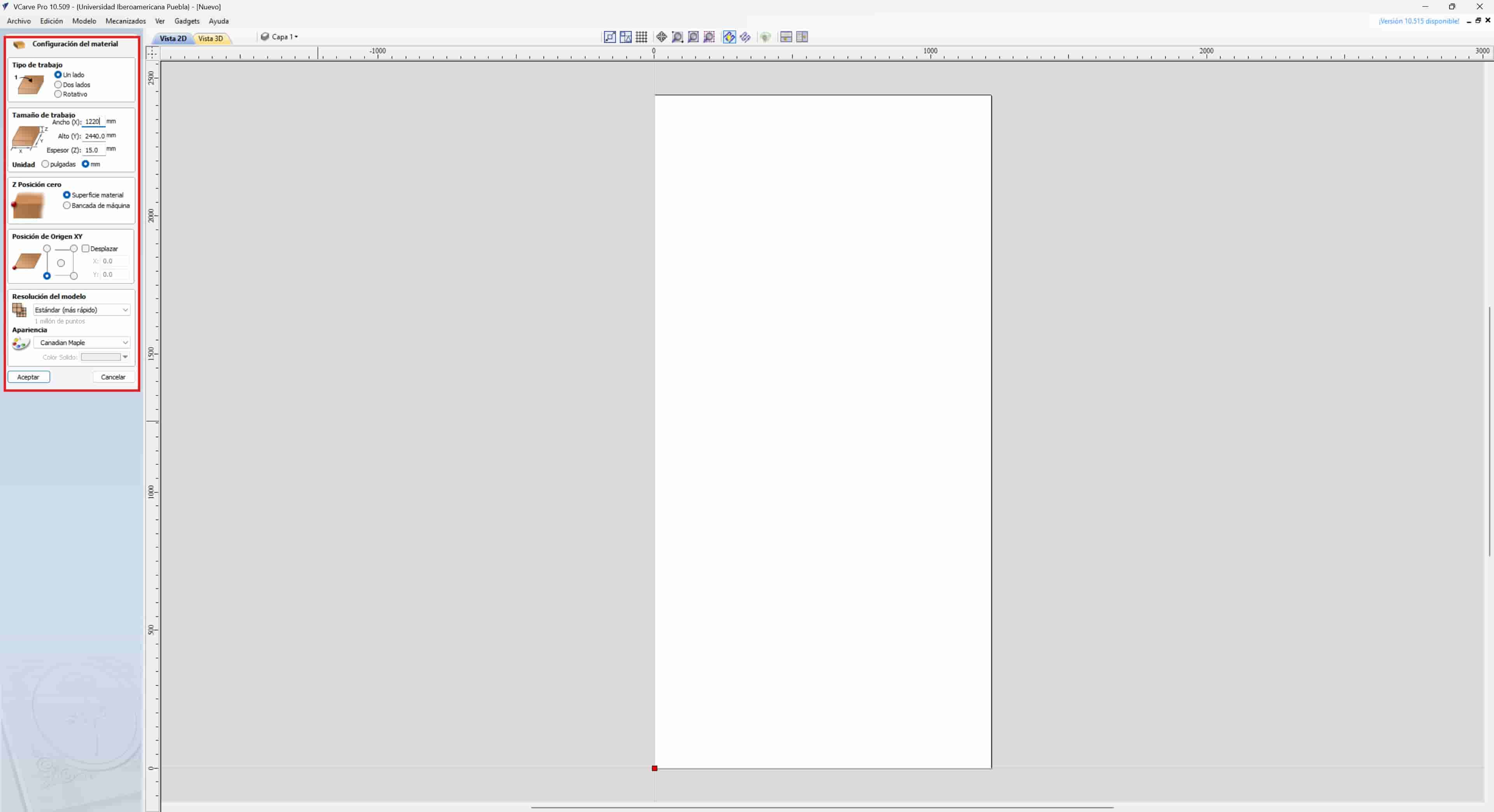
Once we start the program, we select the create a new file option on the left side of the screen. Once in the new project, we will be immediately asked to input certain parameters, such as the dimentions of our material, units and the x, y and z origin positions.
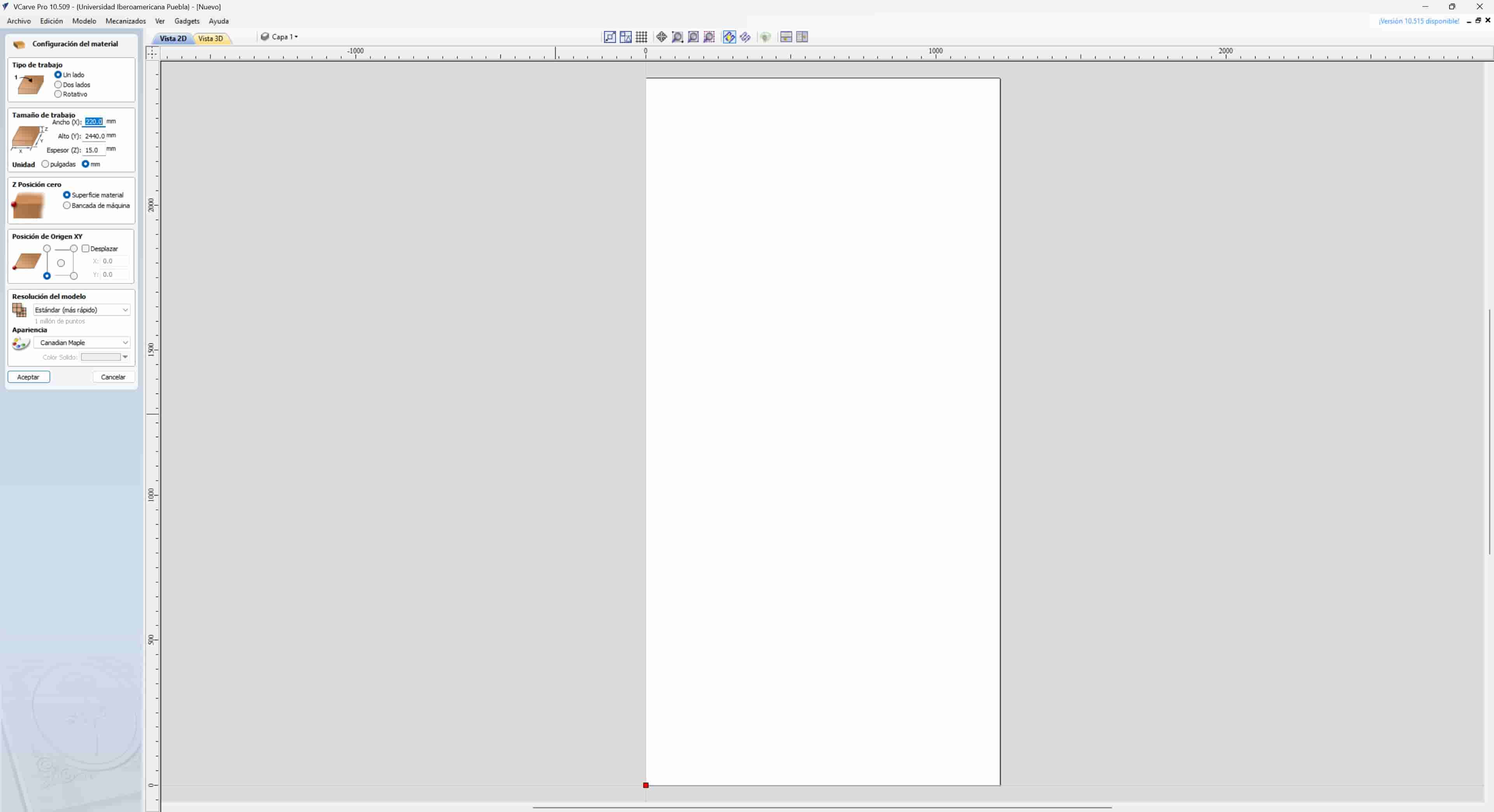
I measured my sheet of plywood and inputed the measurements into VCarve, these measurements were 1220 x 2440 mm, with a width of 15mm.
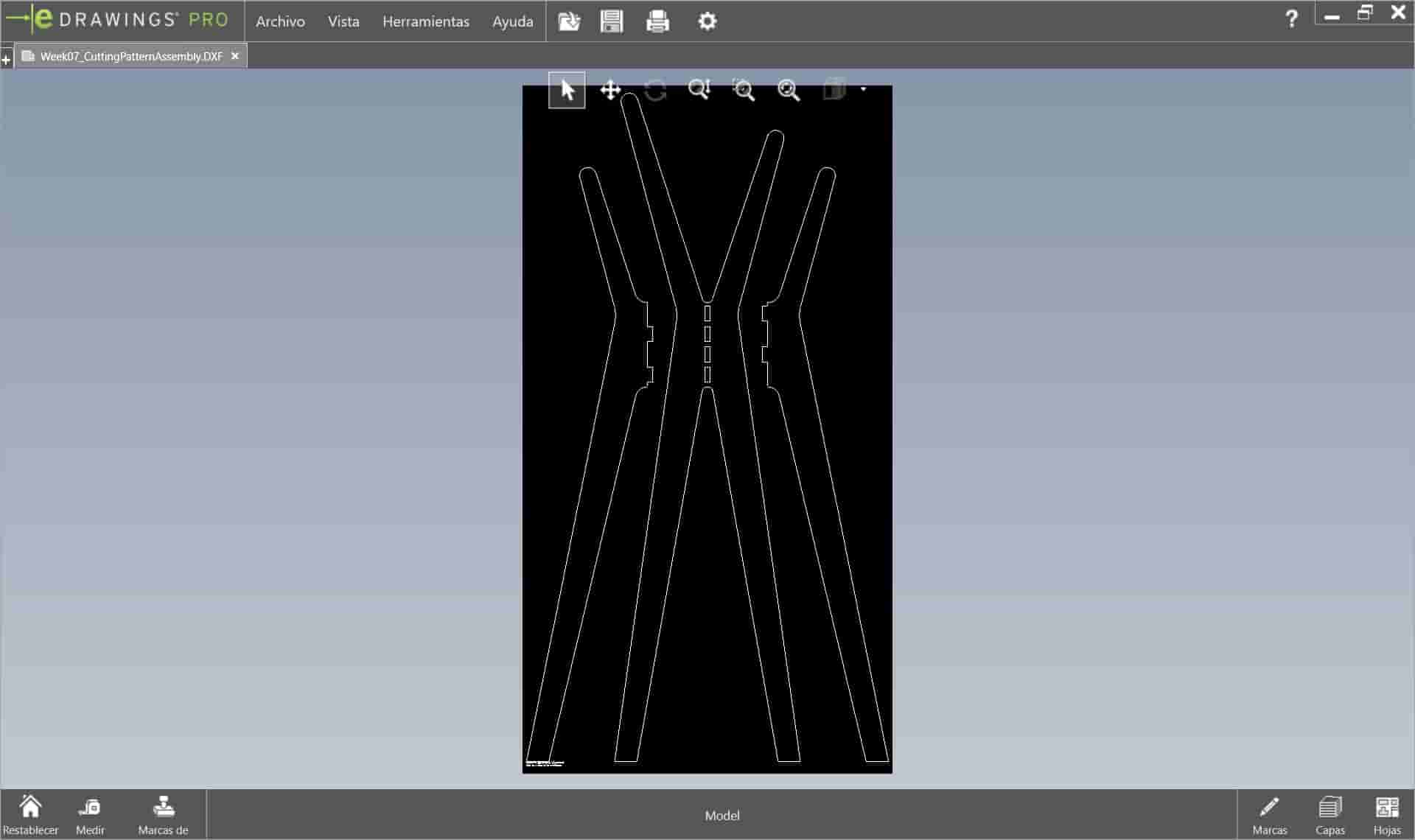
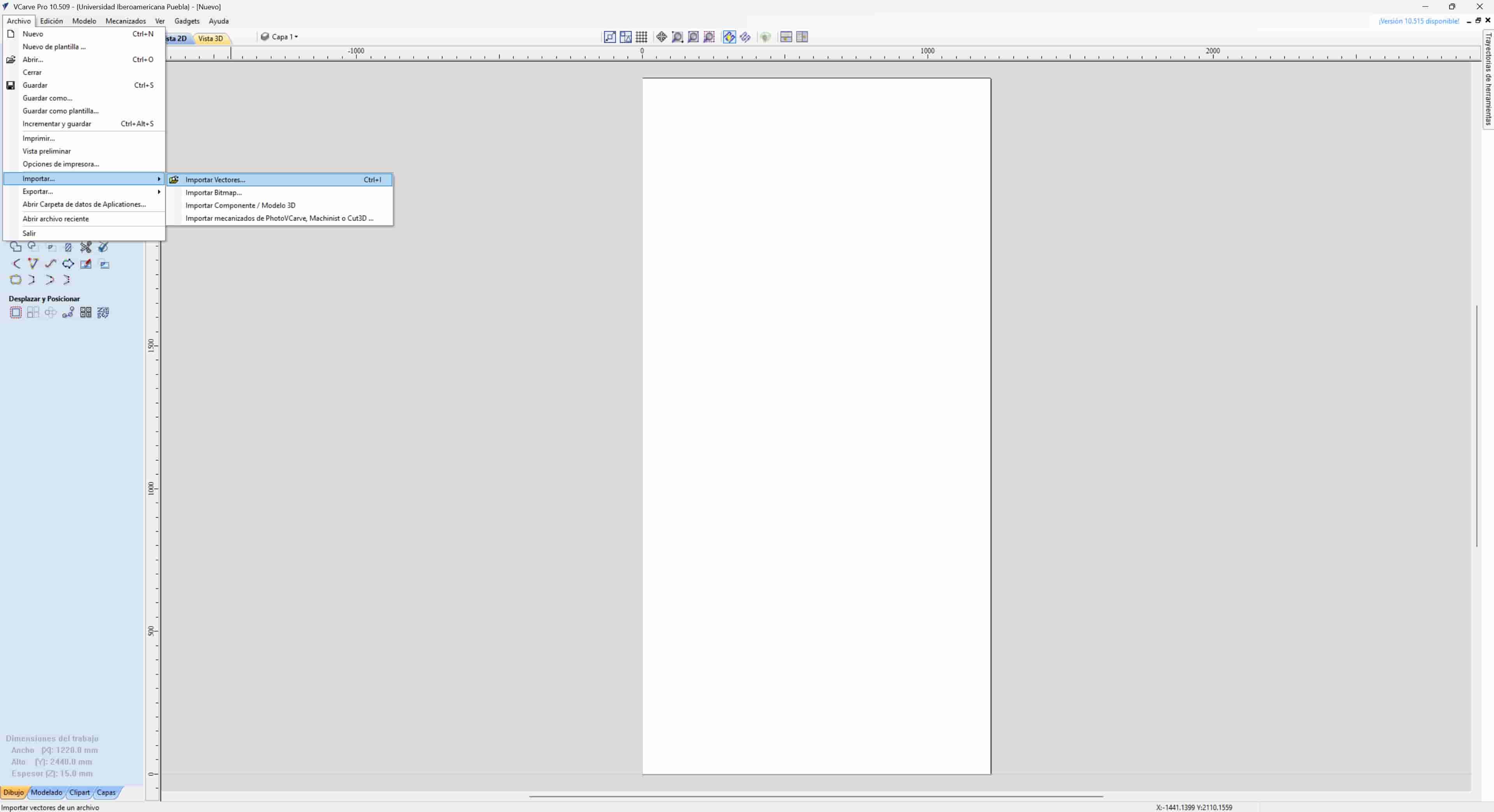
3.2 Import DXF
We import the DXF file that we generated from our 3D model. Once in our program, we can move it around the screen, we want to position it close to the bottom left corner of the work area, but not too close, since we will be using clamps to secure our material.
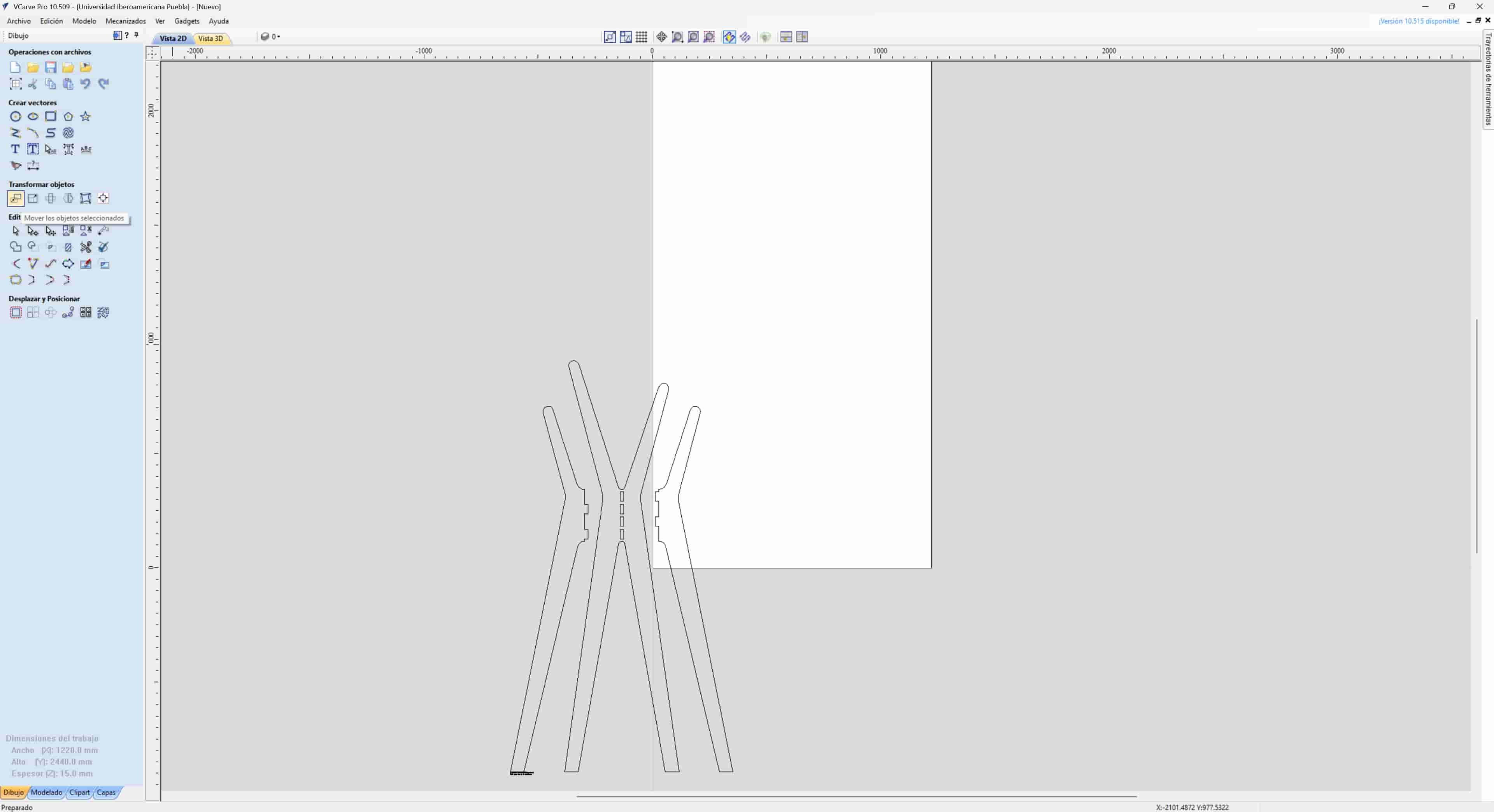
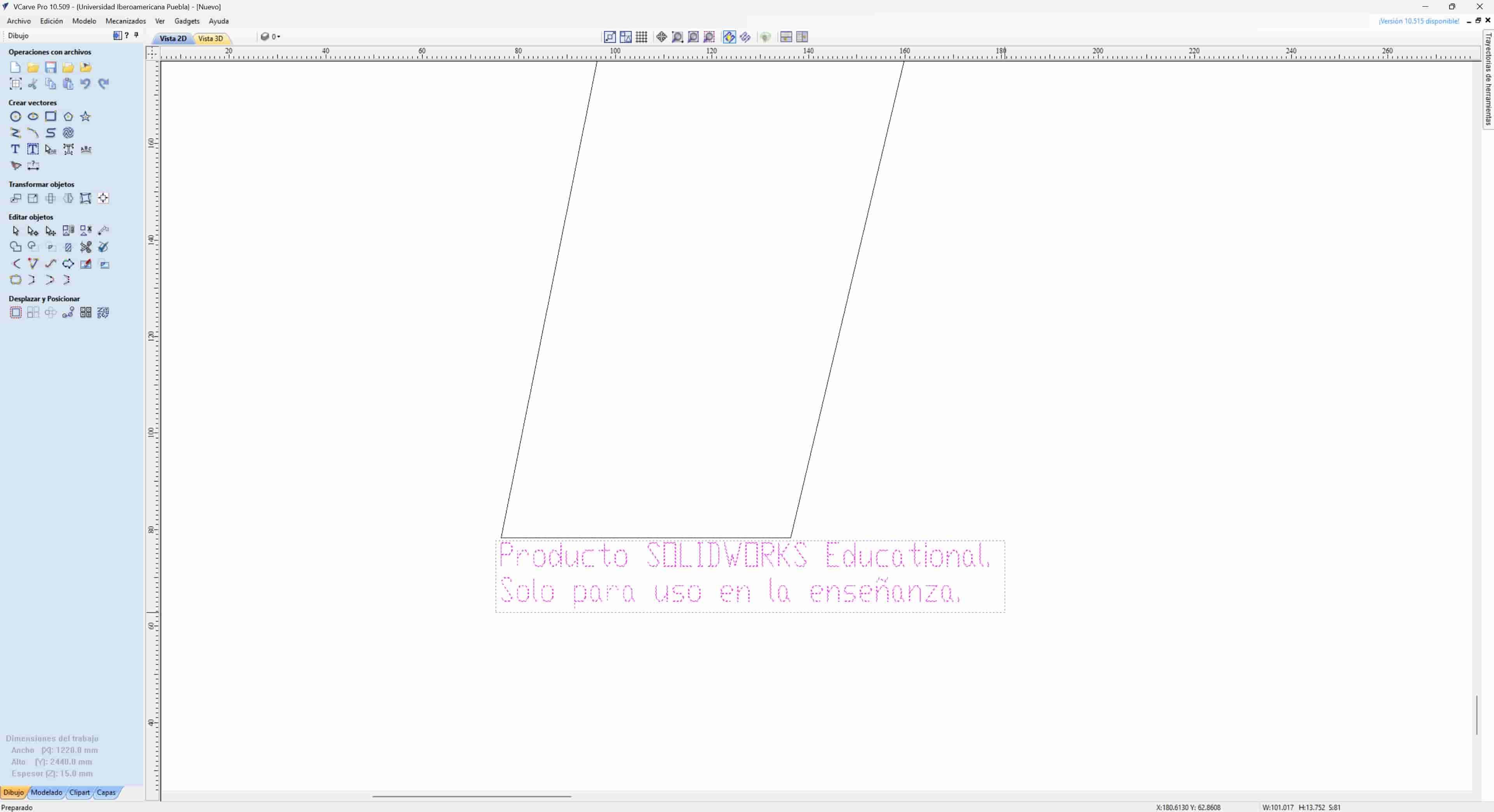
Additionally, I deleted a watermark that was left from SolidWorks.
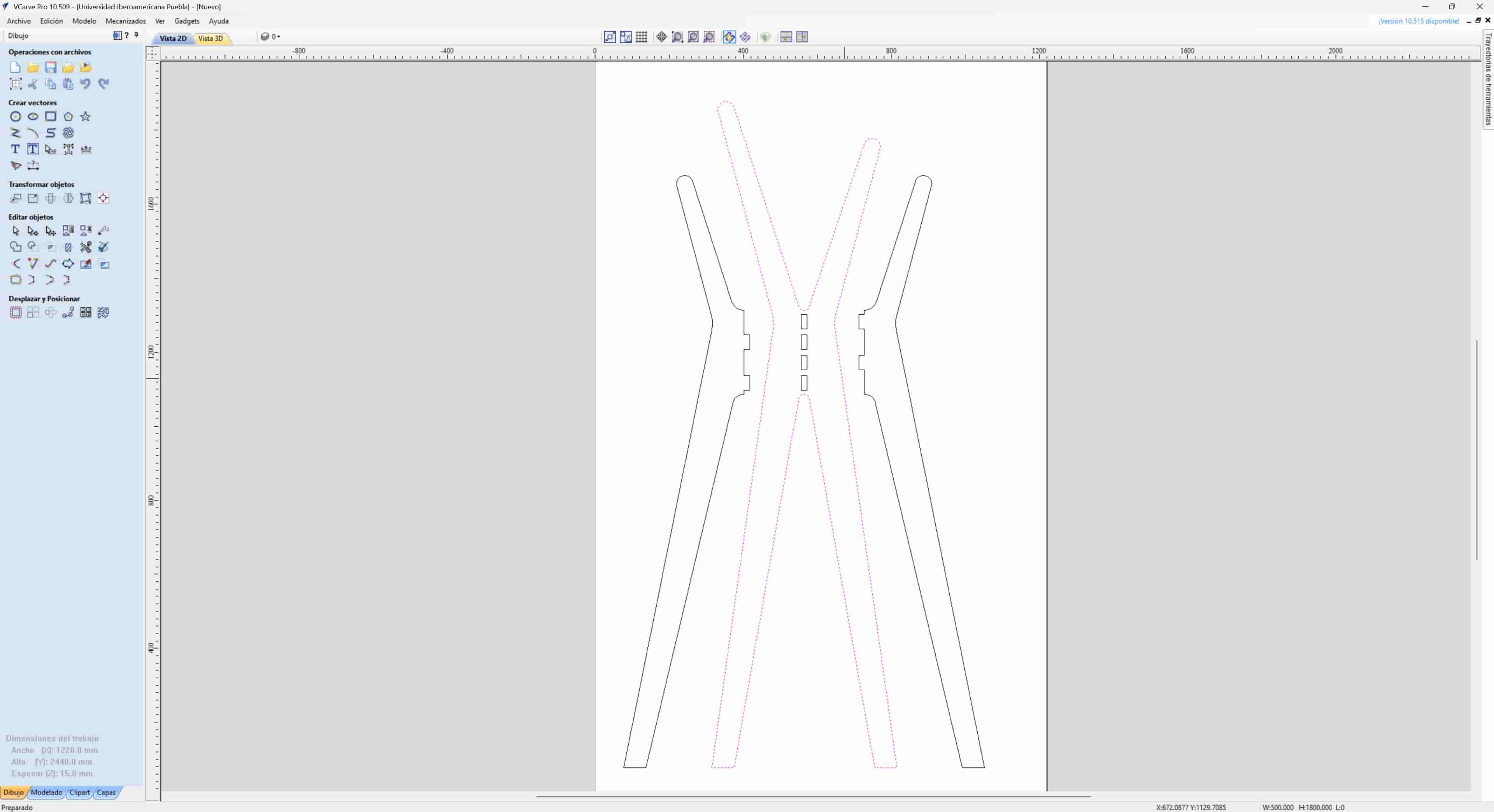
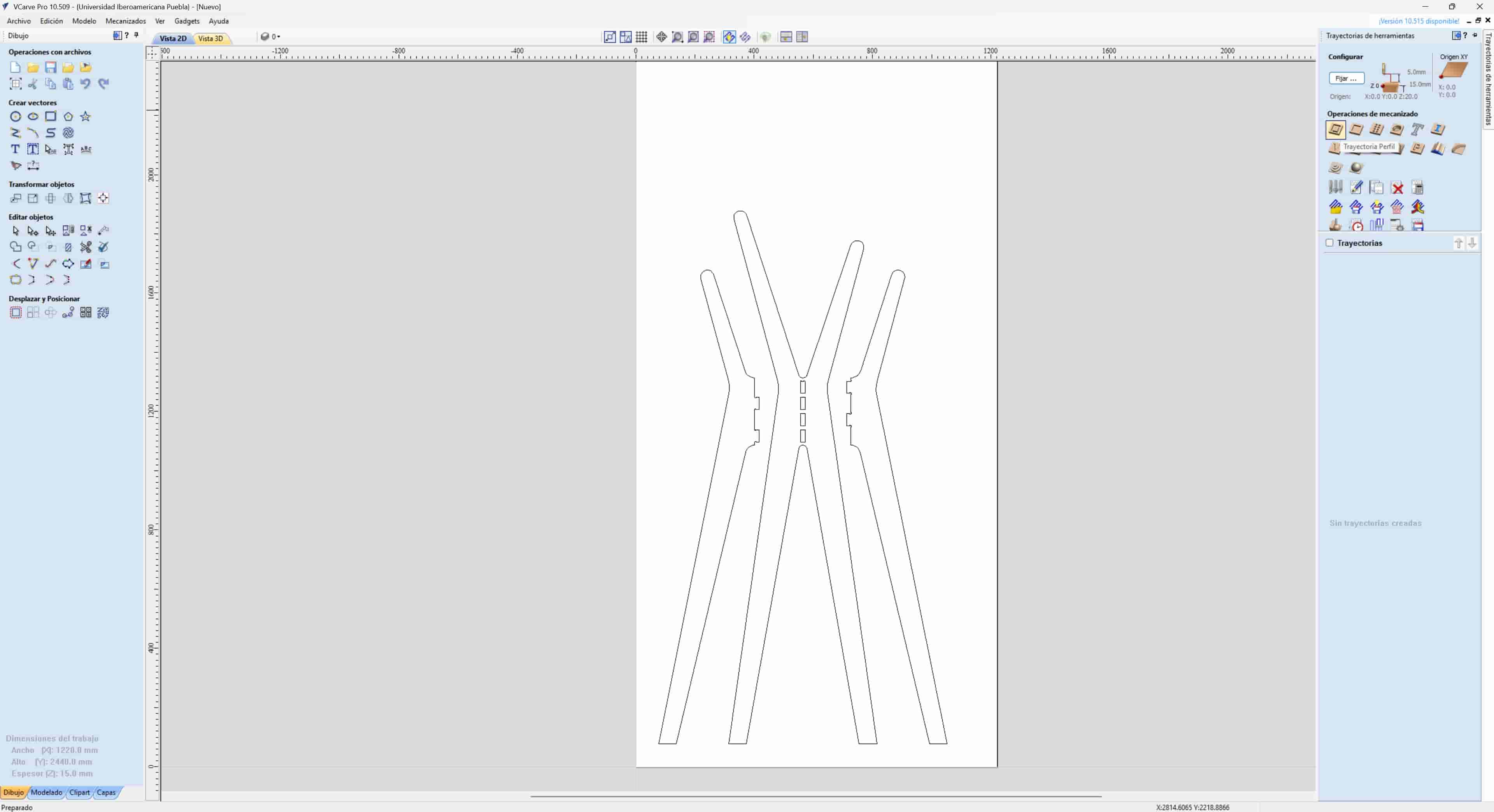
3.3 Merging Vectors
As you may have noticed, each line was imported as an individual vector, but this won't do. We have to join all adjacent individual vectors into a single continuous, closed vector. We do this by selecting the close vectors tool and clicking on two adjacent vectors. We repeat this process until we close all of the vectors.
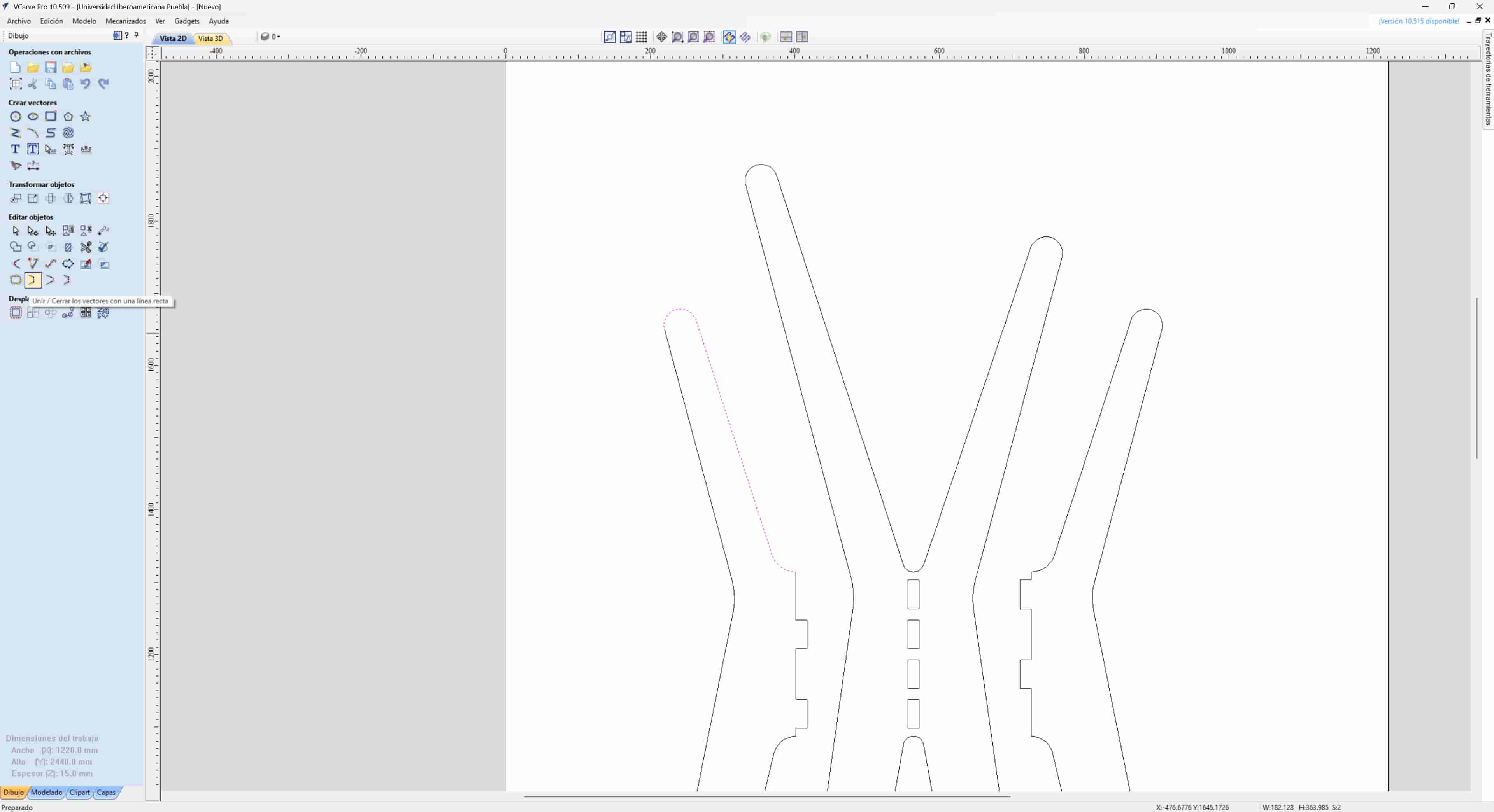
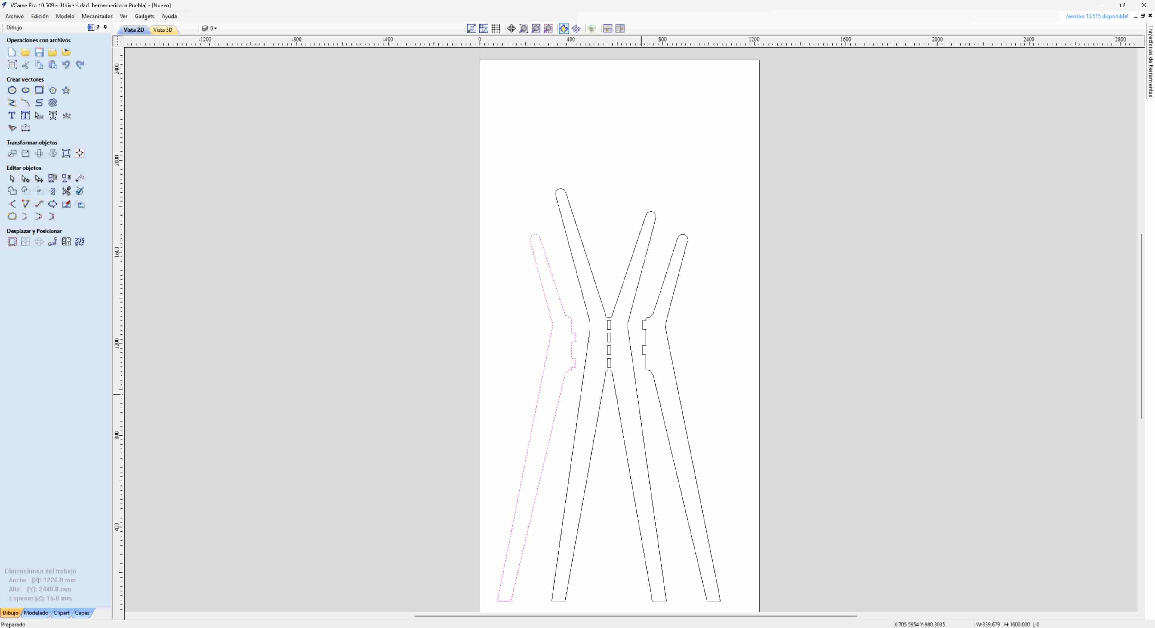
I repeated this process with the remaining vectors.
3.4 Chamfers
Since we are using a cylindrical end mill, we can't properly cut interior 90° cuts, we can solve this problem by adding round chamfers in each interior corner, with the same radius as our tool.
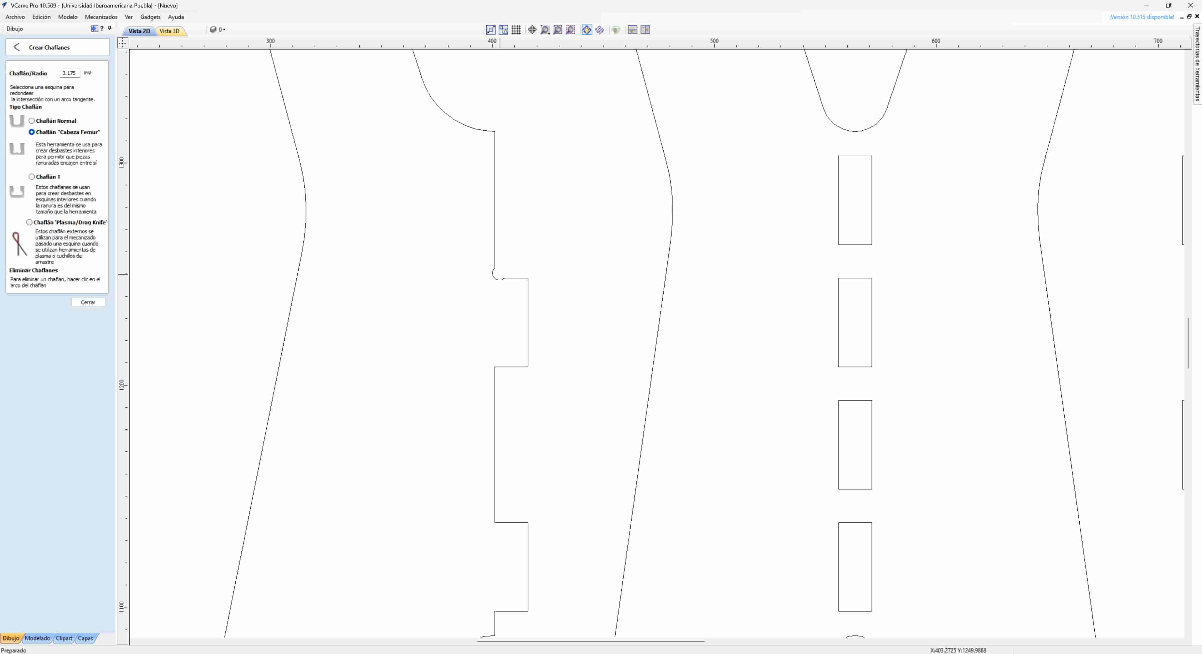
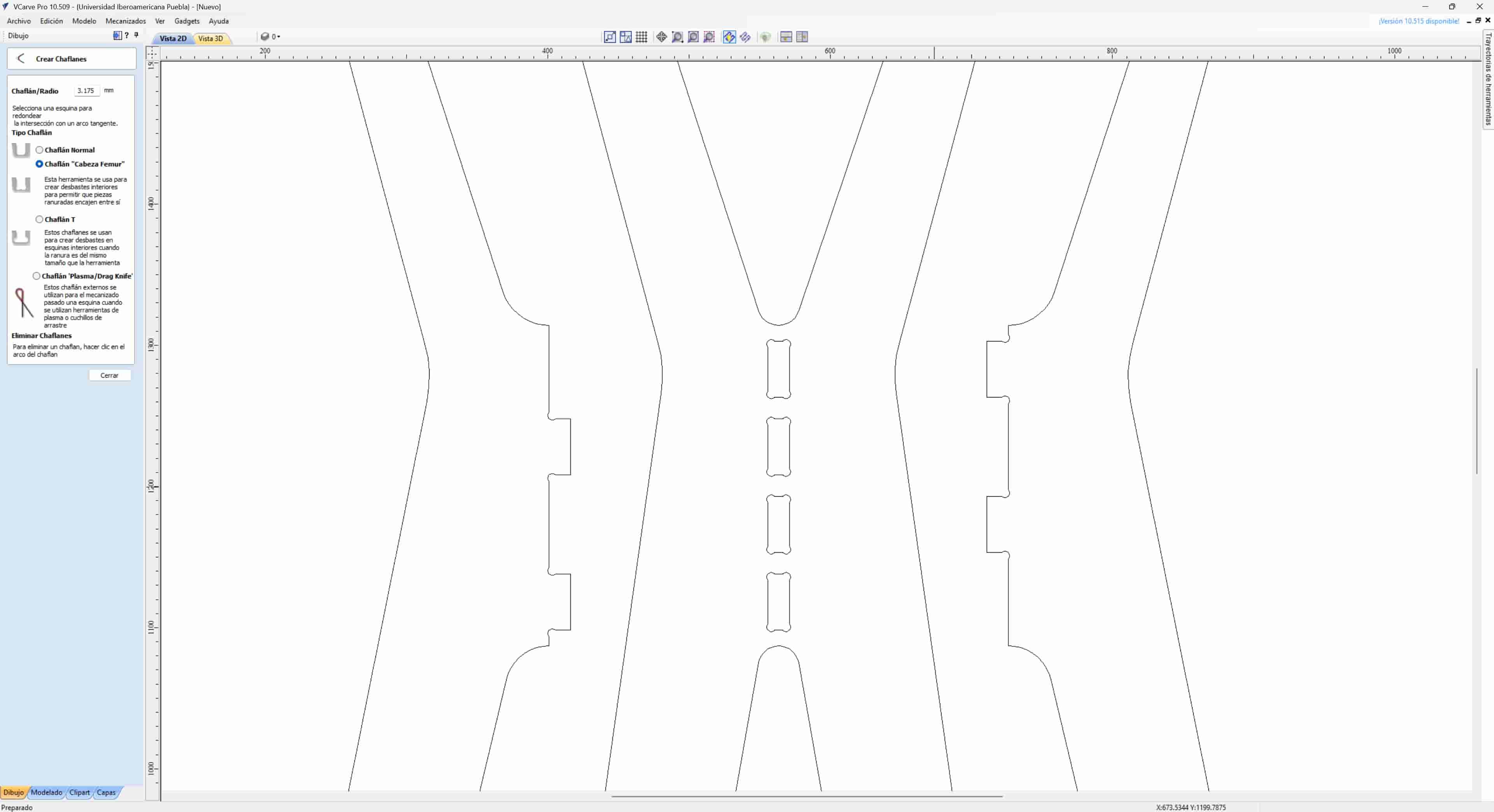
This will ensure a correct fit between our joints.
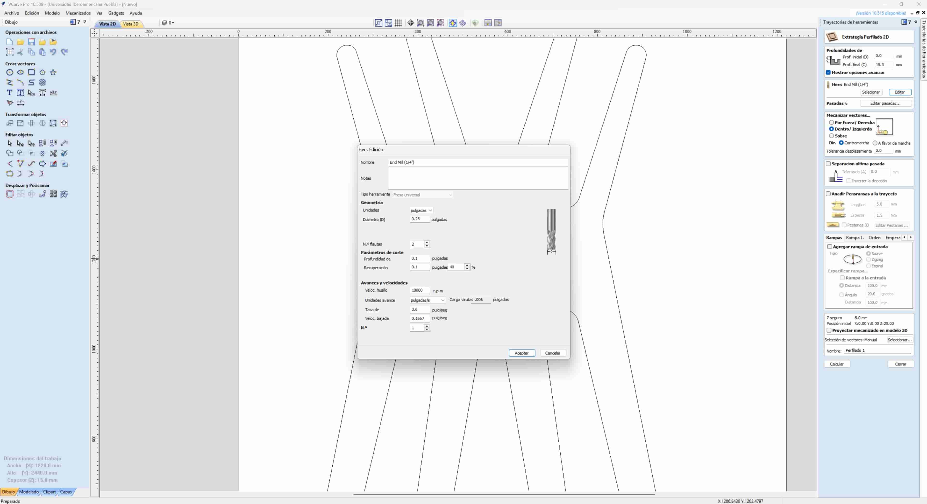
3.5 Tool configuration
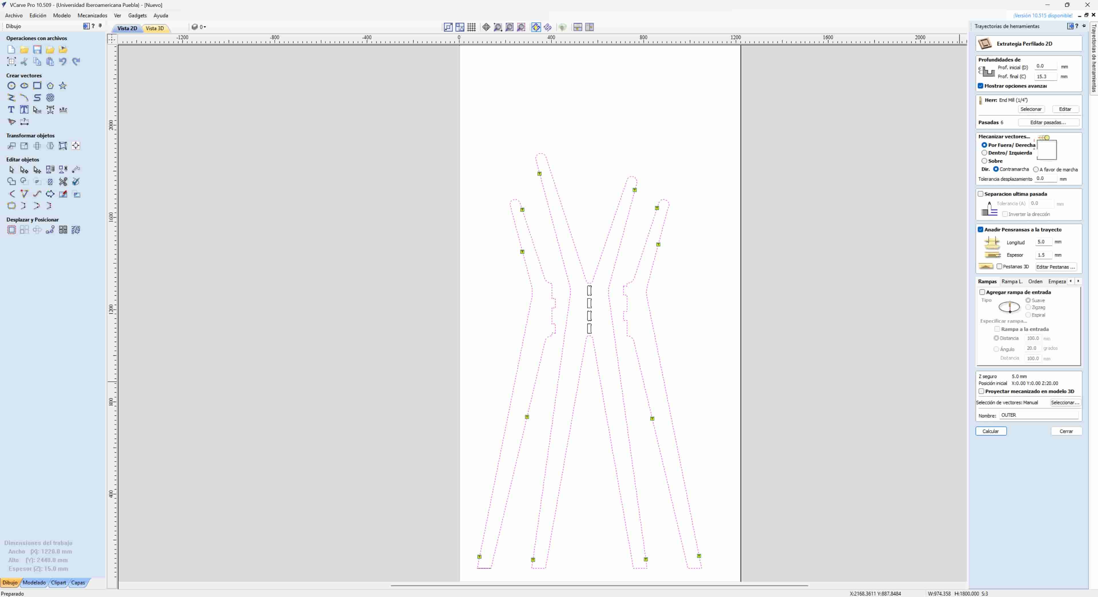
After finishing with the configuration of our vectors, we can configure our toolpaths. First, we open the toolpath menu on the right side of the screen, in this menu, we will choose the profile toolpath option.
Once in the toolpath profile menu, we will first configure the depth of the cut and the tool we will be using. I set the depth to 15.3 mm, since the sheet might be buckled, this way we can ensure that we will cut the sheet in its entirety. To configure the tool, we have to input the exact same characteristics of our physical tool, additionally, we have to configure the rpm and travel speed of the spindle, we can consult a chart or calculator to determine these values, my tool is a 1/4" two flute end mill, with a feed rate of 3.6" per second and 18000 rpm on the spindle.
3.6 Inner Toolpath
Once we have configured the tool, it will be saved for any additional toolpaths in the file. We will begin by setting up the inner toolpath, which will encompass the square holes on the inside of the main part. We select the squares and open the profile toolpath, which will have the same depth and tool that we configured earlier, the main characteristic of this toolpath is that it has to be cut from the inside of the squares.
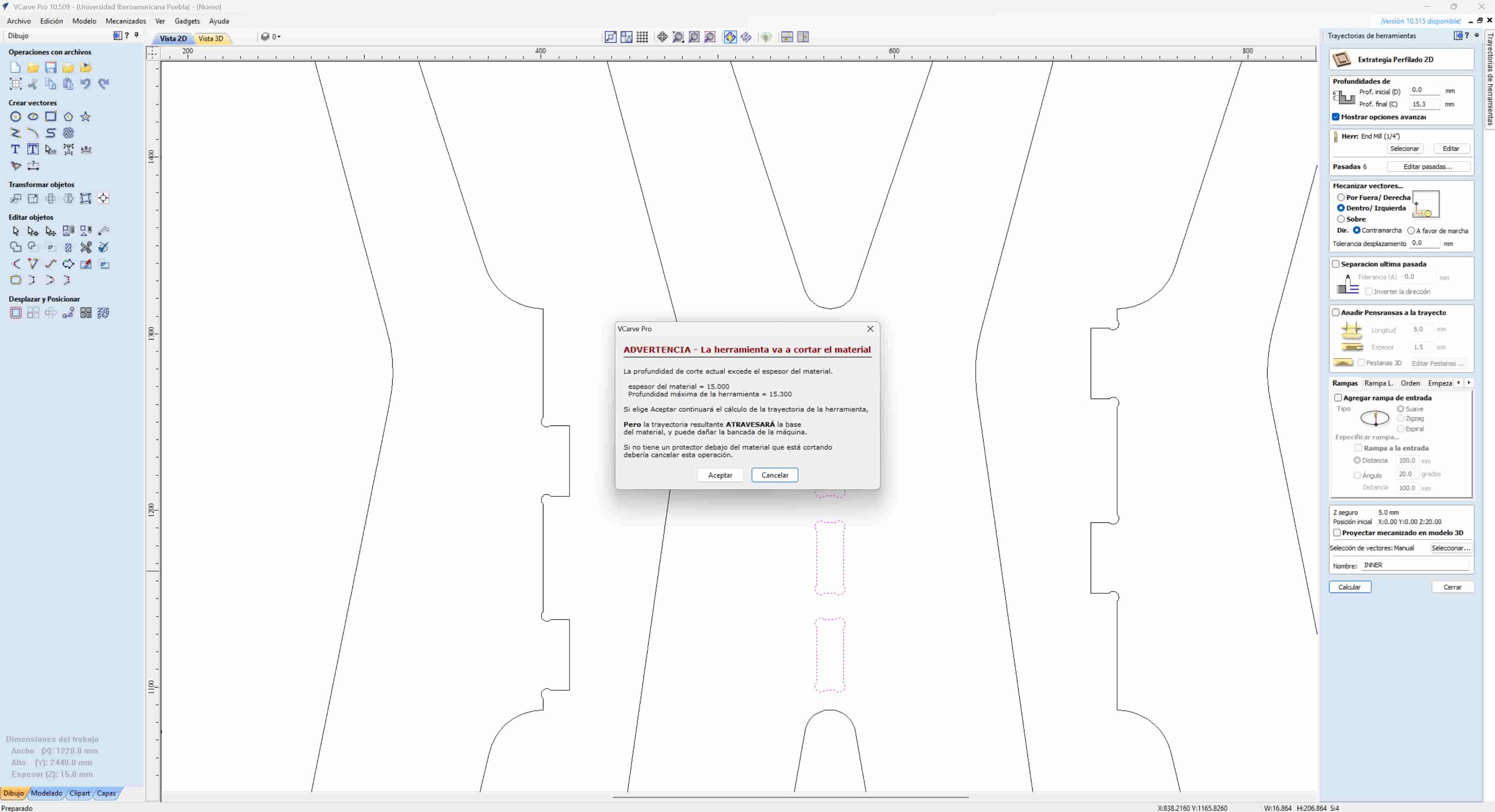
Once the path is configured, we add a name to it and press the calculate button at the bottom of the profile toolpath menu. This will save the toolpath to our file.
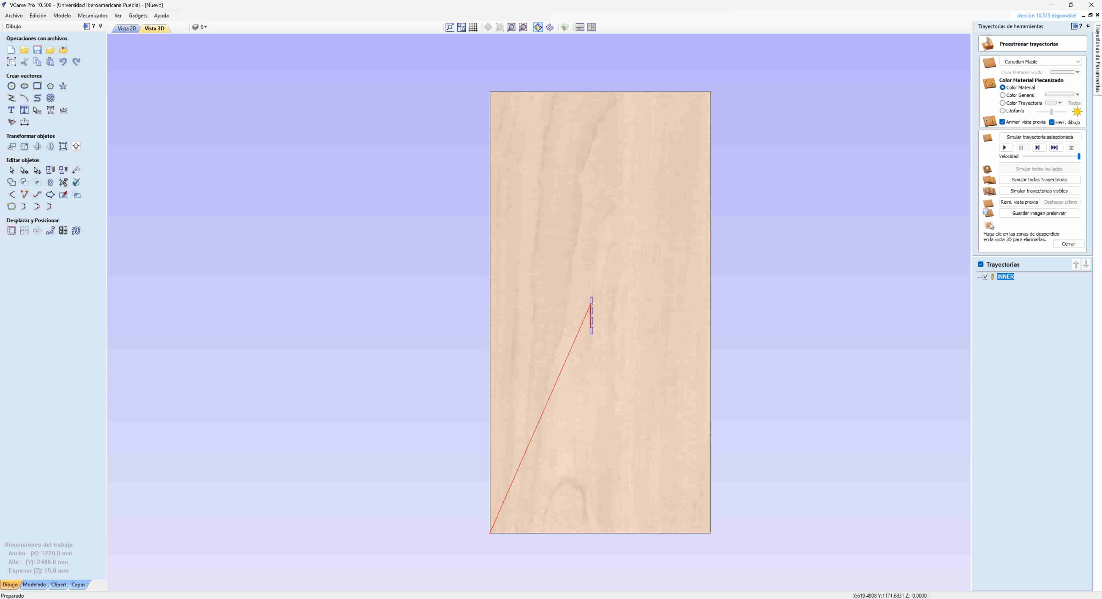
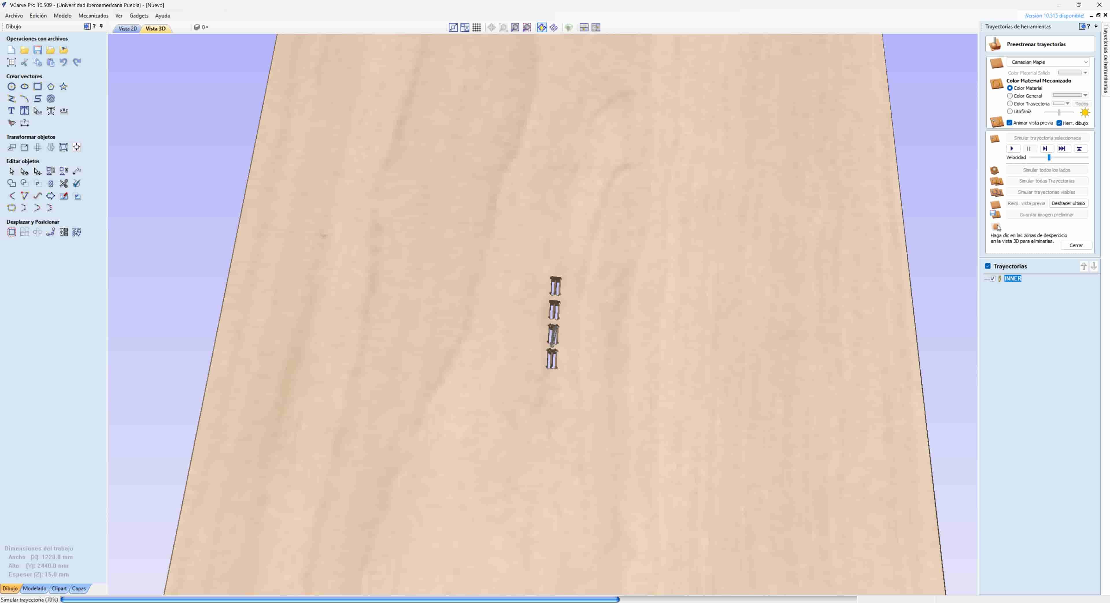
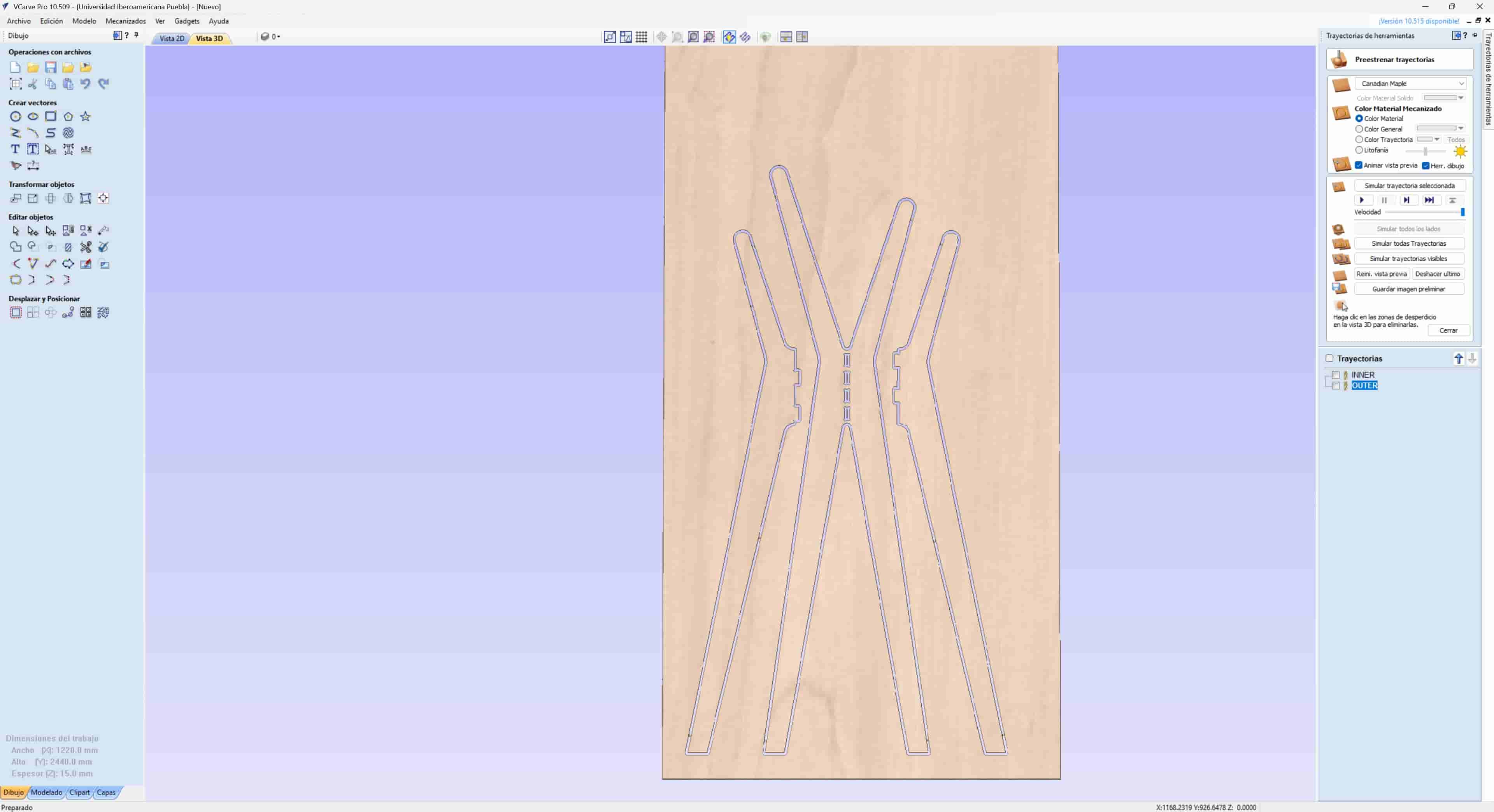
3.7 Toolpath Simulation
From the toolpath menu, we can select the simulation option or change from 2D to 3D view. In the 3D workspace, we can simulate the path that our tool will follow, the red lines represent where the tool will move above the material, the green lines represent where the tool will descend into the material, and the blue lines represent the path that the tool will traverse inside the material. We can also play an animation of the process.
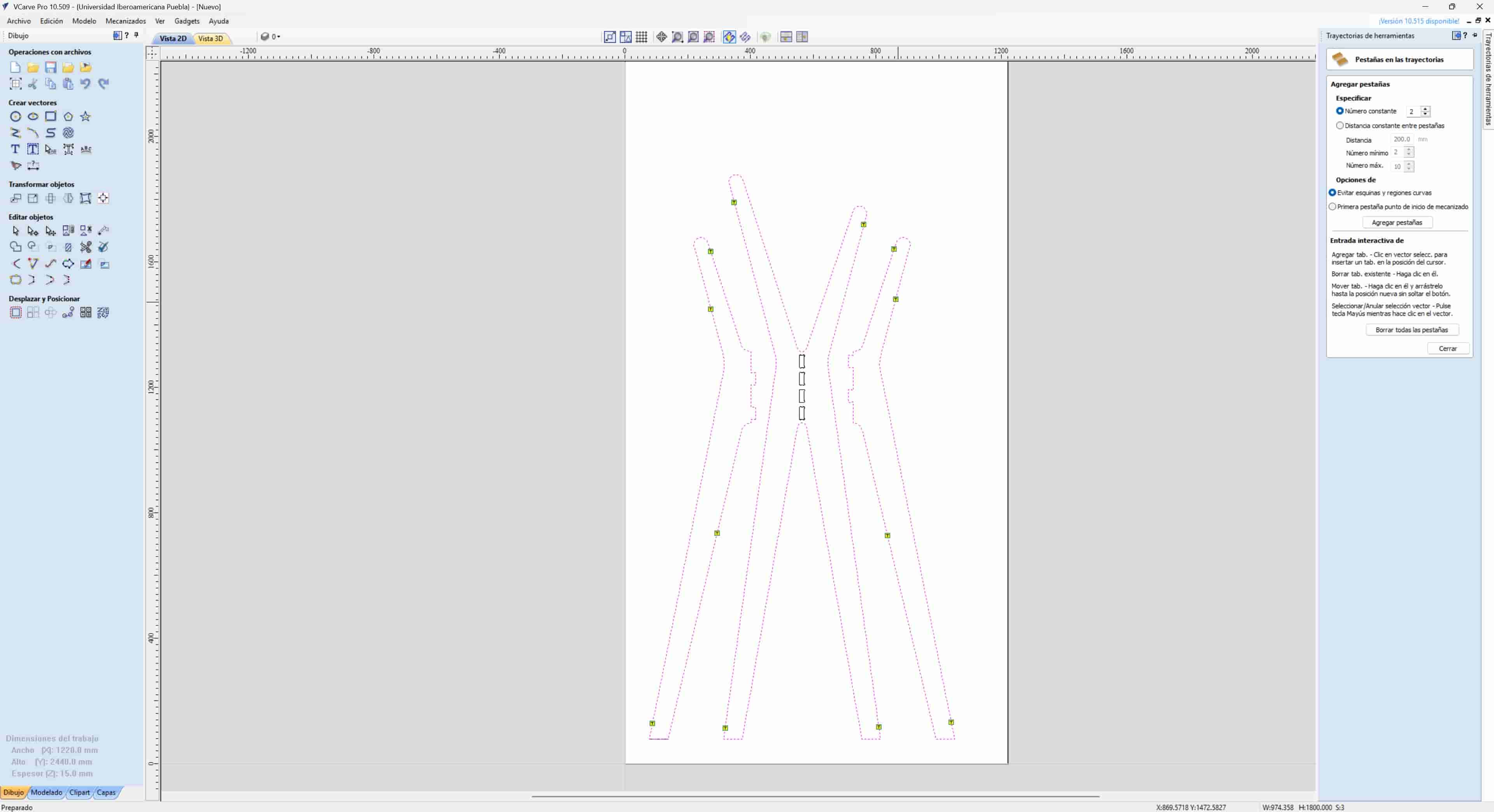
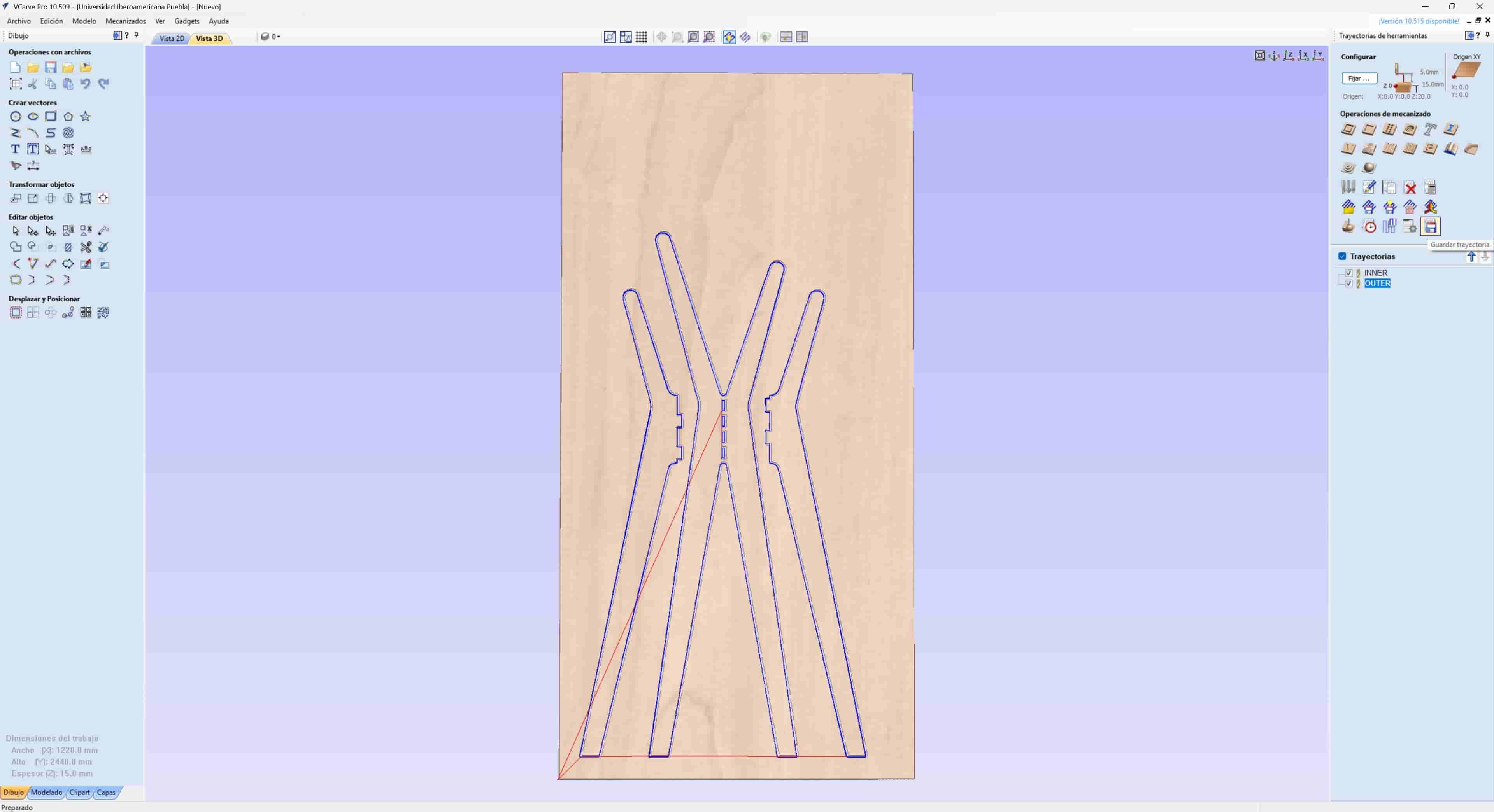
3.8 Outer toolpath
To configure the outer toolpath, we select all of the vectors of the outlines of our parts, and open the profile toolpath menu, we then change the mechanized vectors to the outside and activate the add tabs option, this will maintain small bridges between the carved parts and the sheet, which helps in stabilizing the part.
Once we have configured the toolpath we name it and calculate it, same as before.
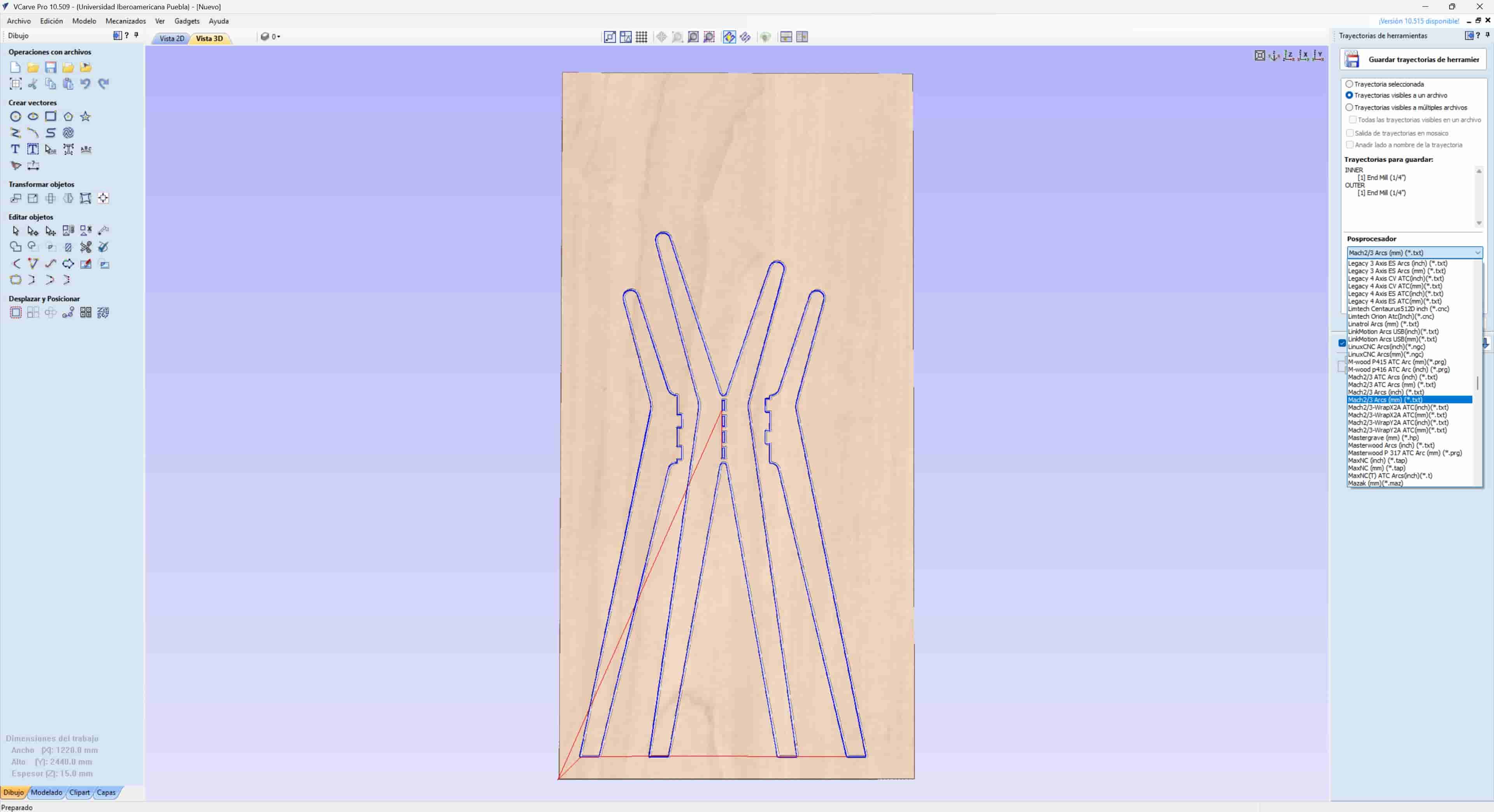
3.9 Save Toolpaths
The final step is to save our toolpaths, to do this, we first have to select the postprocessor, which is specific to the router that we will be using, for the red router in our lab, we use the Mach2/3 Arcs (mm) (*.txt), the black router uses the AsiaRobotica-NK105.3-arcs (*.nc), but, to use the later, we have to load our program to a specific computer in the lab and process it from there into our USB drive.
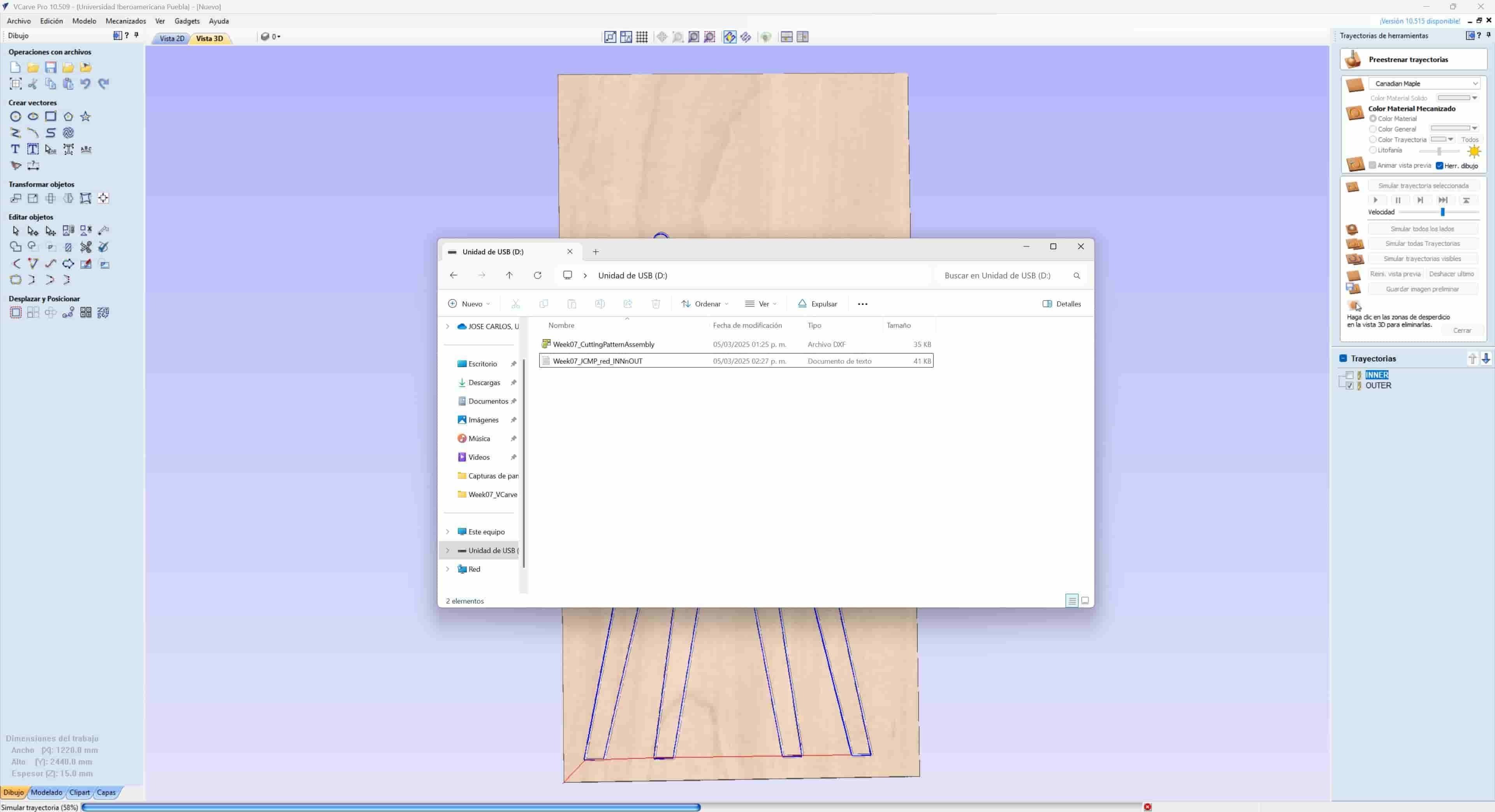
When we have our postprocessed files, we have to copy them into a thumb drive to load them into the machine.
4. Router Operation
I used the AsiaRobotica router, which is equipped with a small hand-held control terminal, and uses metal clamps to secure the material to the machine bed.
Before taking a look at the carving process, we have to note some important security meassures, since this machine is considerably more dangerous than any other machine that we have used up to now.
- Security Equipment - When using the machine, we have to wear a labcoat, safety boots and safety googles, additionally, I recommend using a respirator since the process generates a great ammount of dust.
- Secure Material -The material should always be tightly secured to the machine bed, this should be done either with nails or with clamps, depending on the machine bed. If we are using nails, we have to make sure that the end mill won't collide with them at any point of the toolpath.
- Fire Hazard - When working with flammable materials, there is a risk of a fire if our rpm and travel speeds are not correctly balanced, this should be properly calculated when establishing the parameters in the CAM software, but we should be ready for a fire emergency at any point in time.
- Process Supervision - The machine should not be left alone during the carving process, we should always be ready to stop the process at any point in time by using the emergency stop button.
- Safe Distance - The spindle of the machine rotates at great speeds, and poses a significant health hazard if we come in contact with it, so it is imperative to keep an eye on it at all times and maintain a safe distance. This is important to consider with any other moving parts, since they can also pose a crushing hazard.
- Cleaning - The process generates a lot of waste material in the form of dust and splinters, we would usually use a vacuum pump, but it is not operational at the moment, so we use a broom to push the waste off the sheet and collect it in a bin. Additionally, when we finish the process, we should take the leftover parts of the sheet to a container.
4.1 Procure Materials
As stated before, we will be working with plywood sheets, when we procure them, we should try to select the least buckled sheet that we can find, this is because even when we secure the material, the sheet will lose its structural integrity when we start carving it, worsening the buckling and potentially ruining our parts.
Aditionally, the sheets are quite heavy, so I suggest asking for help to carry it to the machine.
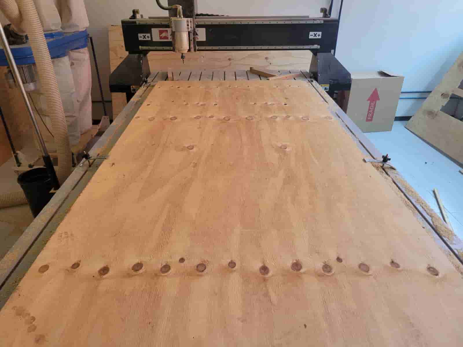
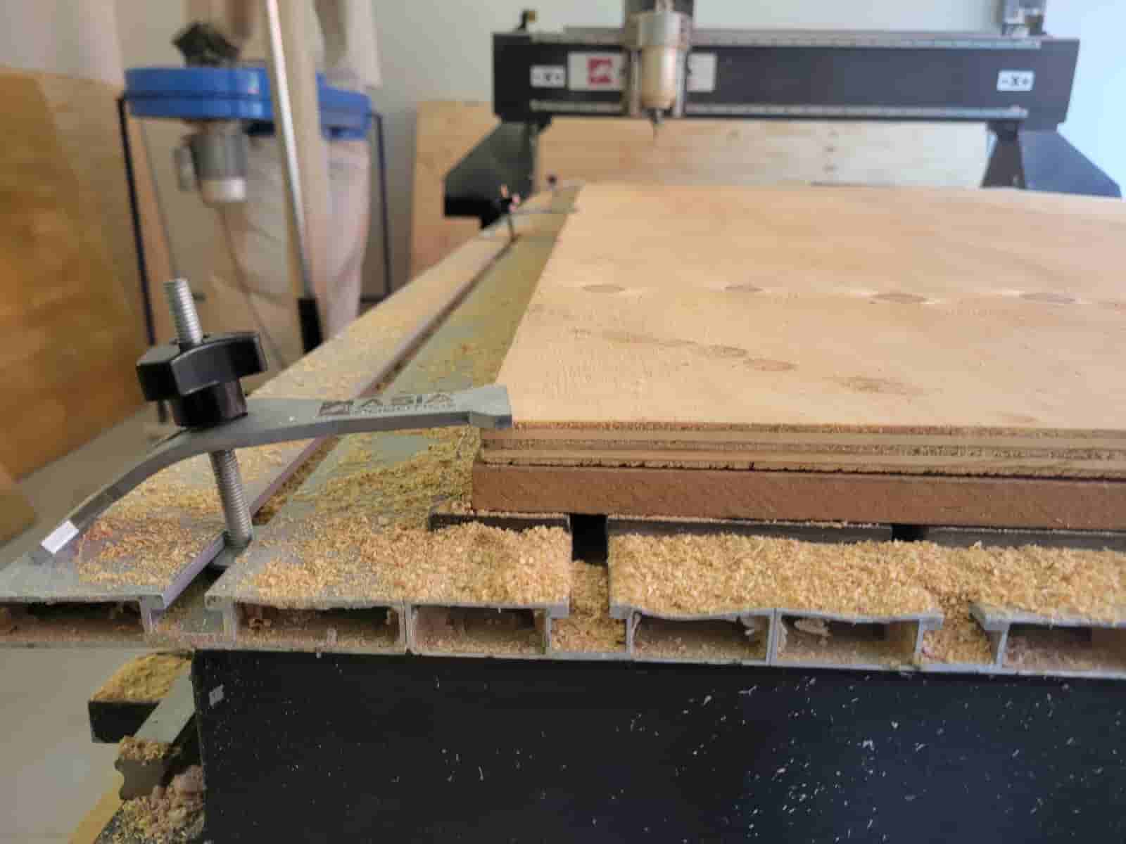
4.2 Secure the material
We place the sheet over the machine bed, trying to align it as much as possible to keep it parallel to the bed. Once aligned, we place clamps on the borders of the sheet to keep the material tightly secured. We should try to distribute the clamps in symmetrical pattern aroundthe sheet, but we can also adjust their position to reduce buckling in certain sections along the borders.
4.3 Machine Controls and Activation
On the front right of the machine, we will see a green and red button, these are the power and emergency stop buttons respectively, we can also observe an USB port and a small terminal with buttons and a screen, stuck to the machine with magnets.
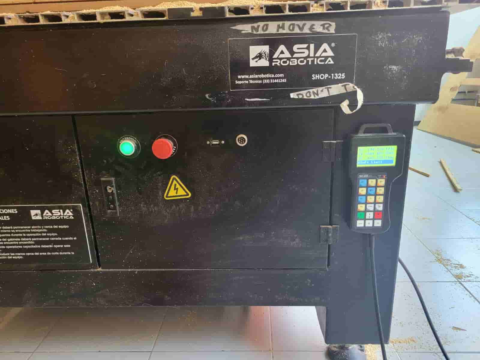
This control terminal will allow us to control the machine, we can grab it with one hand and use the buttons to perform various actions.
When we press the green button, the machine will activate and do a self calibration which will take around a minute.
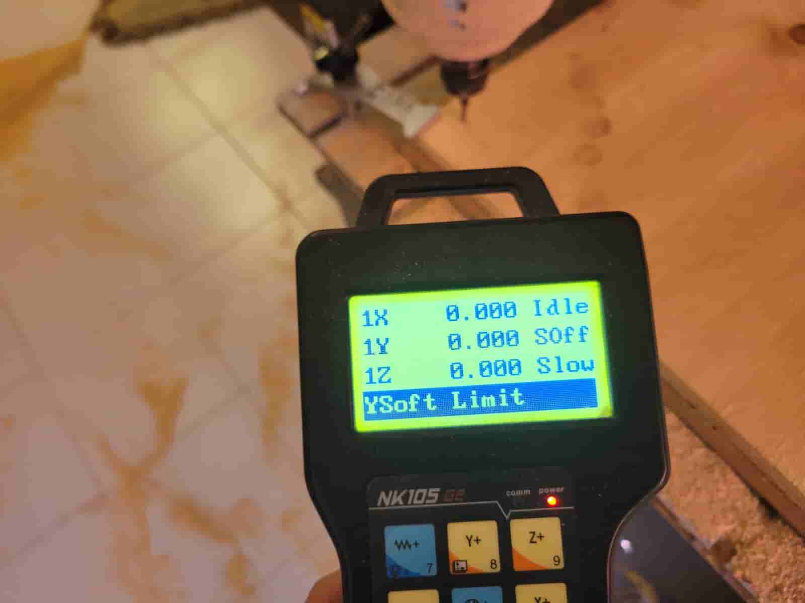
4.4 Zeroing the Machine
The first thing that we will do with the control panel is to establish our zero coordinate in the X, Y and Z axes, we do this by pressing the X, Y and Z buttons, which will move the toolhead to our desired position.
We begin with the X, Y coordinates, which will be positioned near the left corner at the front om the machine, we have to make sure that the clamps are far enough from the end mill such that they wont collide at any point. When we are in the correct position, we press the XY=0 button, which will establish our 0 coordinate.
Once we have determined the XY=0, we begin to lower the toolhead with the Z- button, we have to be careful not to lower it too much or too fast to prevent damaging the tool. Once we are about an inch from touching the sheet, we press the shift button, which will change the movement mode to steps, allowing us to move our toolhead more precisely and carefuly. We grab the spindle and begin rotating it by hand while lowering the toolhead in steps until we can see the sheet starts to get scratched, we then hold shift and press the XY=0 button, which will establish our Z 0 coordinate.
One final important consideration after zeroing the machine is raising the toolhead so that it wont come into contact with the material immediately after starting the carving process.
4.5 Load Program
We insert the USB drive into the port at the front of the machine and press the button with the three lines, located at the right of the XY=0 button. To navigate the file menu we can use the up and down arrow buttons, we will select the USB option and select our file.
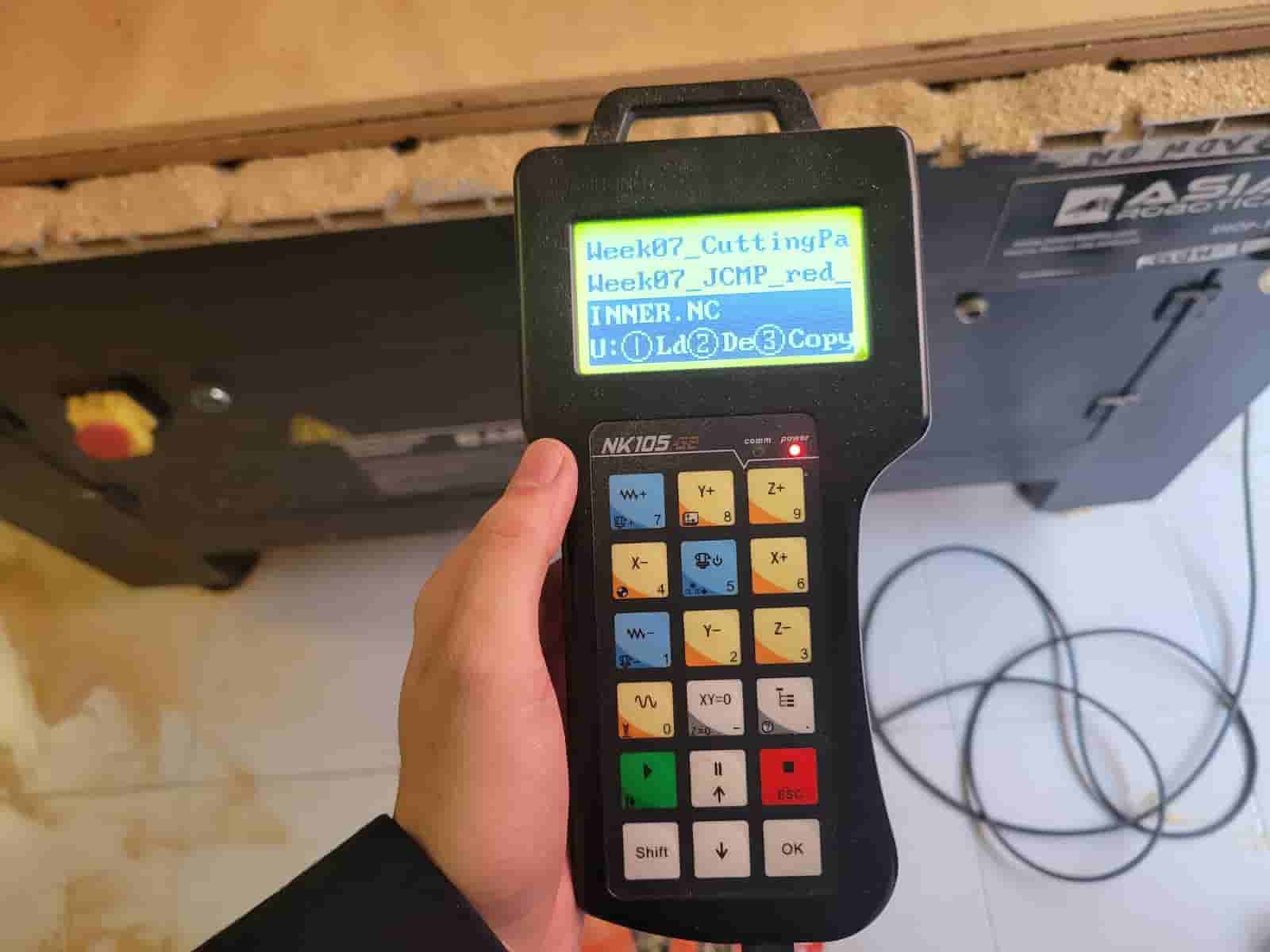
Once we have selected our file we will press the Z button to load it into the router's memory, with this, we are now ready to begin carving.
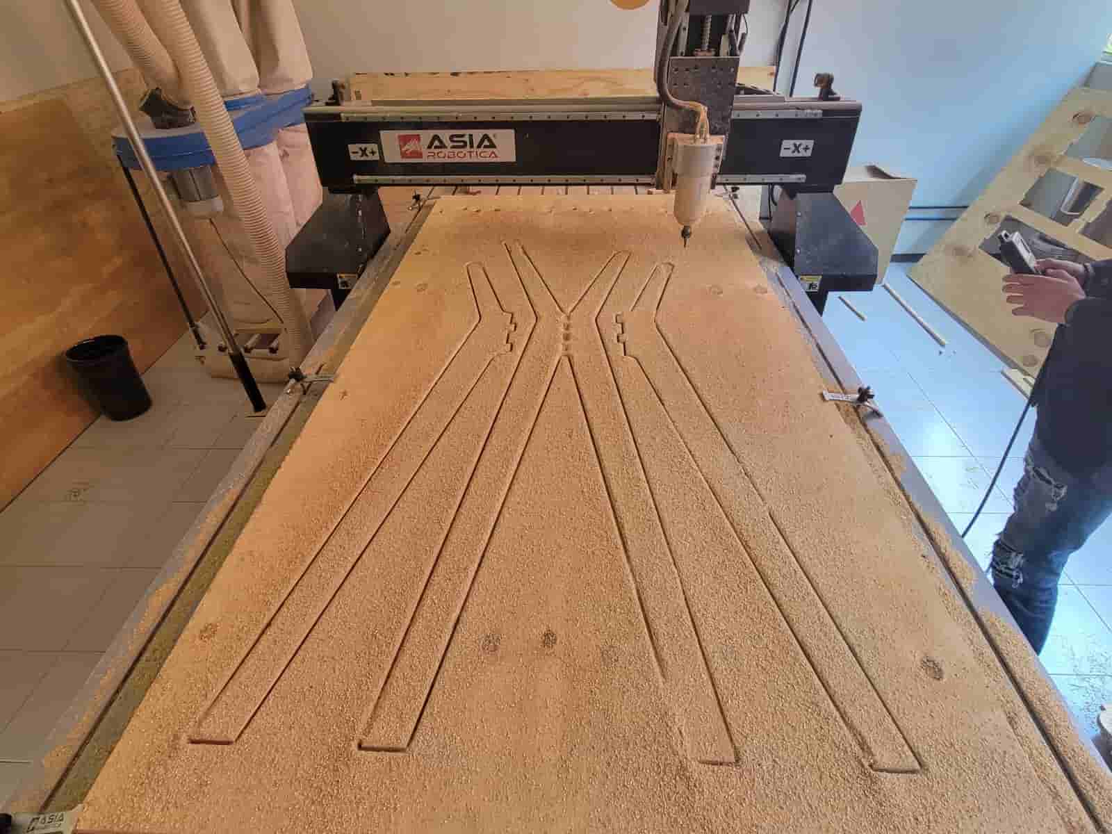
4.6 Begin Carving
We access the file menu again, but now we go to the router memory menu, we select our file and press the green button. The spindle will accelerate until reaching the established rpm and then it will begin carving our toolpaths.
As stated before, we should supervise the machine at all times during the process, and be ready to press the emergency stop at any time.
4.7 Material Extraction
Once the carving is finished, we move the toolhead to the back of the machine and remove the clamps, we then remove our parts and the leftovers of the sheet.
Finally, we turn off the router and clean the machine bed and surrounding area.
5. Post-Processing
As you may havew noticed, our parts's surfaces are rough and covered with splinters, to obtain a nicer finish, we can subject it to additional processes.
Here's what I did;
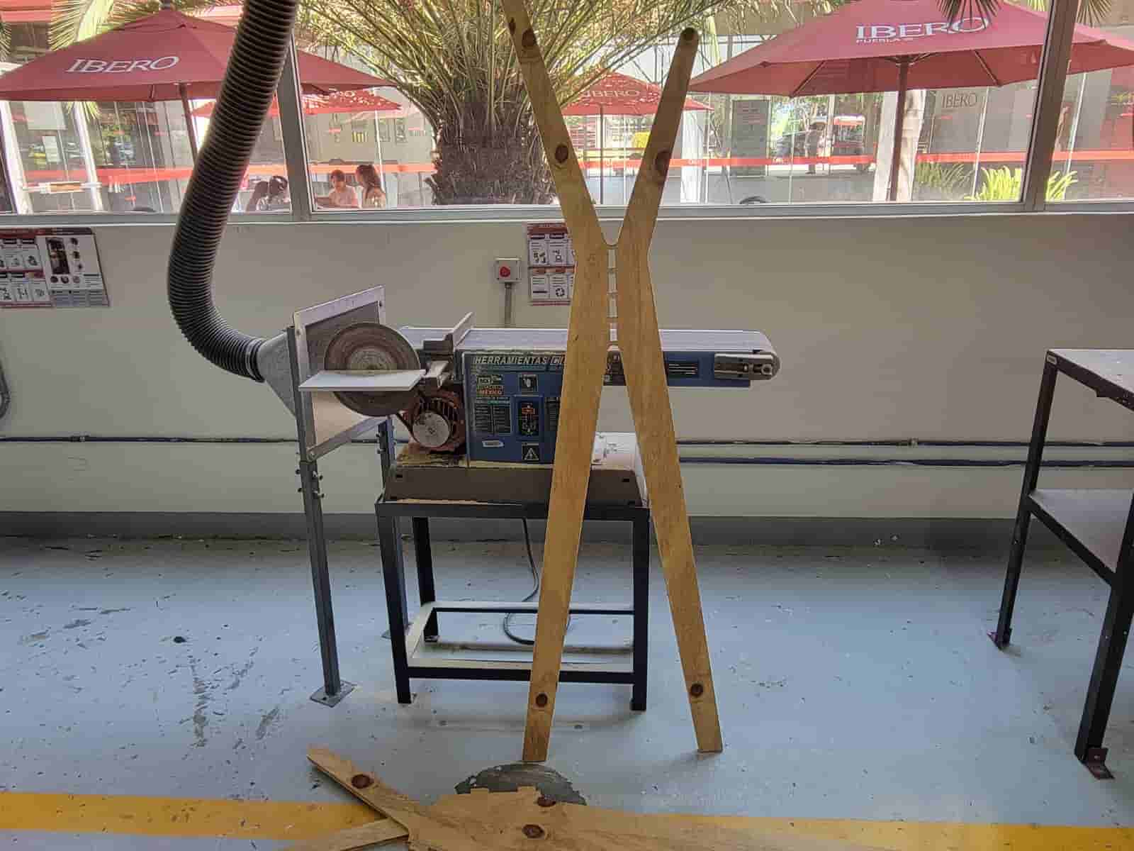
5.1 Belt Sander
I first used a low-grit belt sander to remove the splinters off my parts. I turned on the machine and ran all surfaces trough the sander.
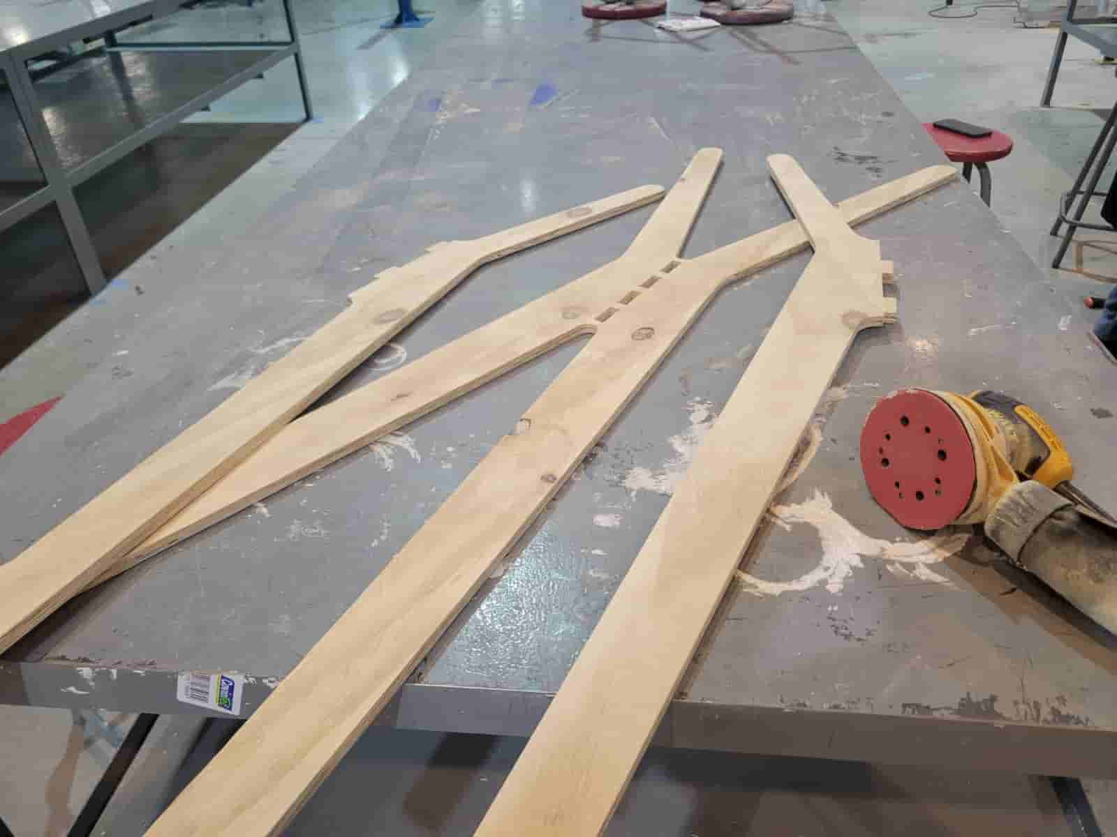
5.2 Hand-held Sander
To give my parts a smooth finish, I used a hand-held sander with high-grit sandpaper. I sanded all surfaces and rounded the edges of the parts, leaving me with a nice, smooth finish that won't leave your hand full of splinters.
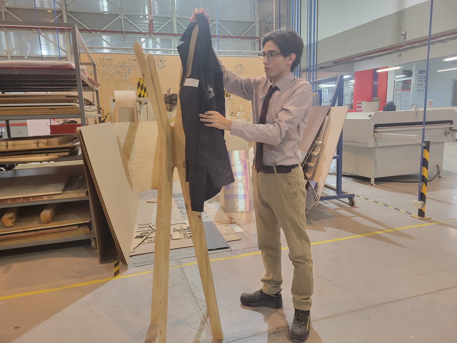
6. Results
Since my coat rack is comprised of three parts, the assembly was very simple, the joints held together tightly but are easily dissasembled with a bit of force.
Without further ado, here are the results;
7. Comments and Recommendations
I want to thank my peers Pepe and Apolo for helping me during the carving process, their inputs were extremely valuable.
The router is a dangerous and somewhat intimidating machine, so I recommend asking for help if you are inexperienced with the machine.
The carving process can take hours depending on your design, so you should organize your schedule with that in consideration.
8. Learning Outcomes
This week I learned how to use CAM software to generate a toolpath and how to operate a CNC router. The final product was a coat rack for my ma, I certainly hope she likes it, perhaps I should paint it.
Files