12. Mechanical Design, Machine Design
Summary
This week we designed and built a machine that includes a mechanism, actuation, automation and application as a team.
My team is comprised by Adriana, Emmanuel, Erwin, Joaquín, and myself.
You can find our machine's group page here.
1. Machine Concept
For this assignment, our team set out to design and build a CNC plotter which is a machine capable of drawing precise vector designs onto a surface by interpreting G-code instructions. A CNC plotter works by translating digital coordinates into physical movement using motors and mechanical components, making it an excellent project to explore the fundamentals of motion control, fabrication, and automation.
We chose this machine concept because it strikes a balance between mechanical simplicity and the opportunity to implement advanced control systems. It involves core aspects of digital fabrication: structure design, actuation mechanisms, electronics, and programming.
2. Individual Contribution - Part and Assembly Design
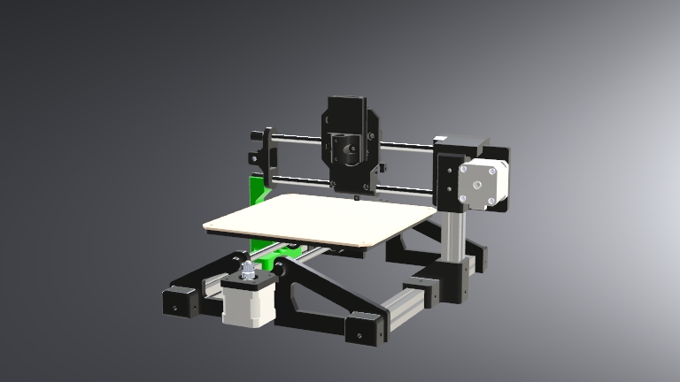
 As part of my individual contribution, I focused on the mechanical design of our CNC plotter's structure and motion system, specifically the parts related to the bed (X axis) and toolhead (Y axis) mechanisms. The plotter uses a belt-driven motion system for both axes, combining precision and cost-efficiency while keeping the design lightweight and fast.
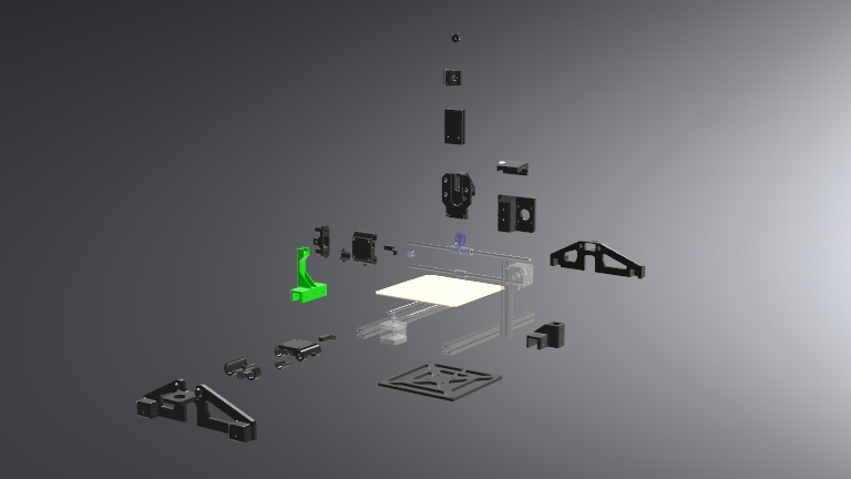
We started the design process by identifying fixed components that would define our constraints. The first of these were the 8x300mm axial steel rods, which we used as linear guides. These rods were easily available, so we used them as a design baseline, ensuring that all related parts would be compatible without needing to modify the rods.
To construct the main frame and provide structural integrity, we used 20x20 mm V-slot aluminum profiles. These profiles form the core chassis of the machine and provide rigidity while also being highly modular. We designed many of the 3D printed parts to have a pressure fit with the profiles. These components are secured using standard M4 nuts and bolts, allowing for easy assembly, disassembly, and adjustments.
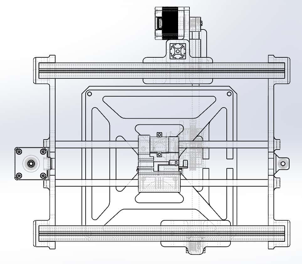
The machine features a mobile bed along the X-axis, and a gantry-mounted Y-axis with a moving toolhead. The Z-axis is simplified and consists of rack and pinion that provides vertical movement for a pen or drawing tool. Most of the machine's structural components were designed for 3D printing, making the system lightweight, customizable, and accessible. The bed itself is designed for laser cutting out of MDF, providing a rigid, flat surface ideal for the plotter's drawing tasks.
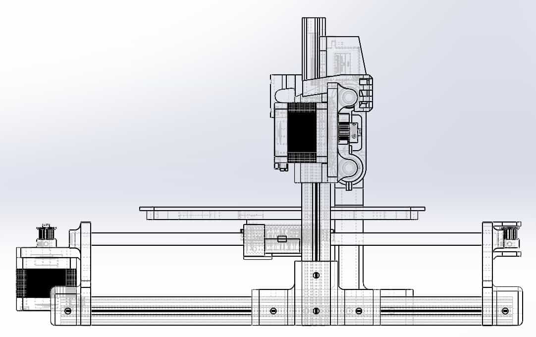
All components were designed and assembled using SolidWorks, allowing us to visualize fits, detect interferences, and simulate movement. Special care was taken to properly align the pulleys and belts to ensure smooth, reliable motion across both axes.
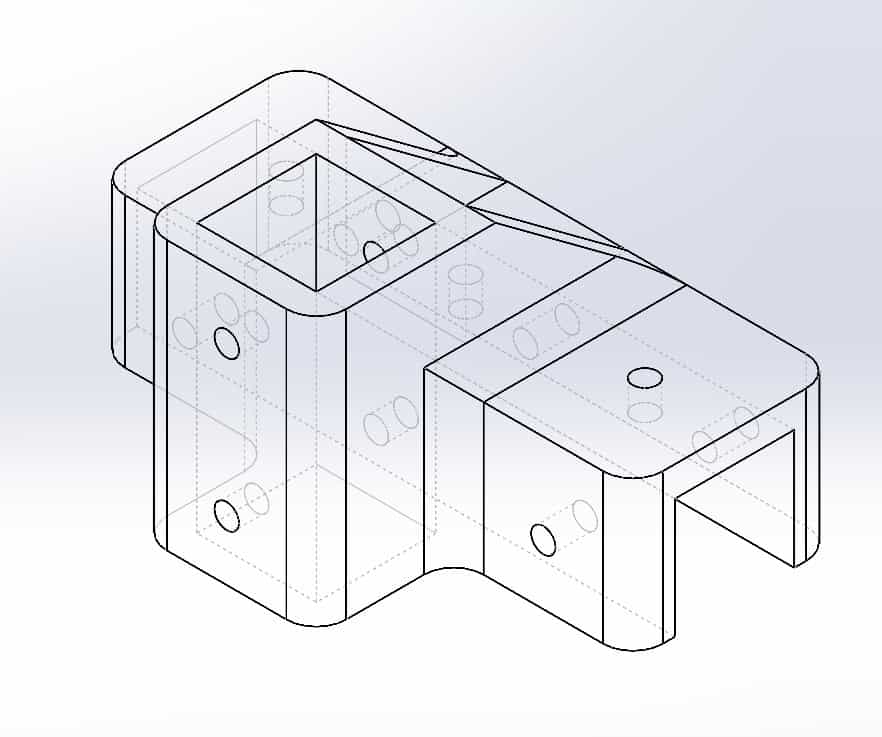
01_Base_Motor Mount
This was the very first part of the design, designed to serve as the main structural support and to securely hold both the axial rods and the stepper motor. The slots on the sides are intended for the 20x20mm V-slot profiles.
02_Base_Pulley Mount
This is the part positioned directly opposite of 01 and serves the same functions, but holding a pulley instead of a motor.
05_Perpendicular Profile Joint
This joint is fixed to the left V-slot profile of the machine and secured using M4 screws. It's purpose is to connect and give support to the structure that comprises the Y-axis.
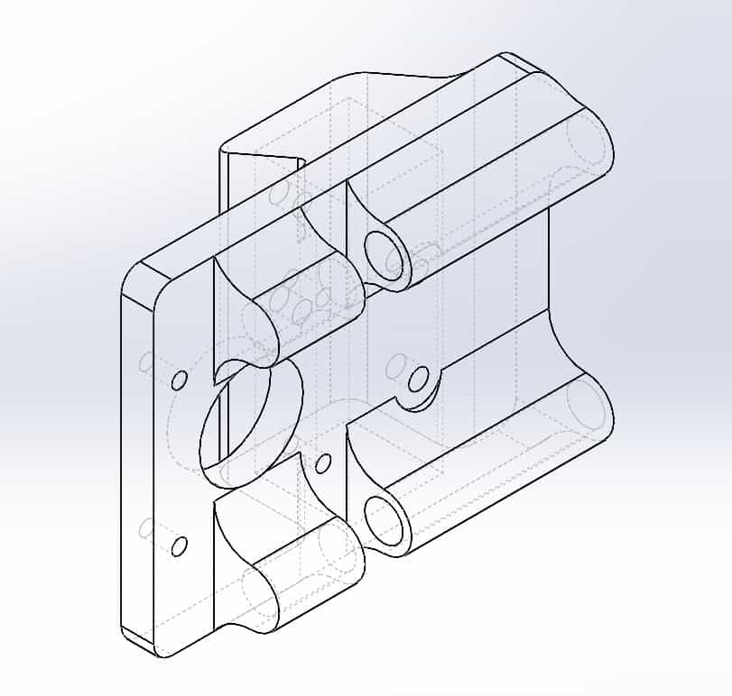
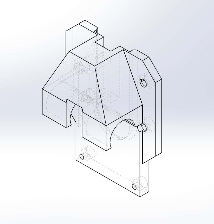
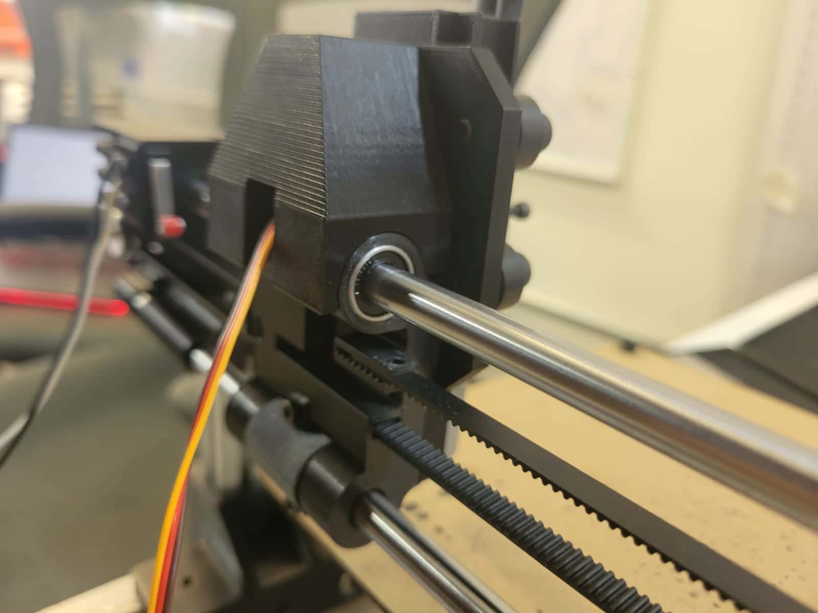
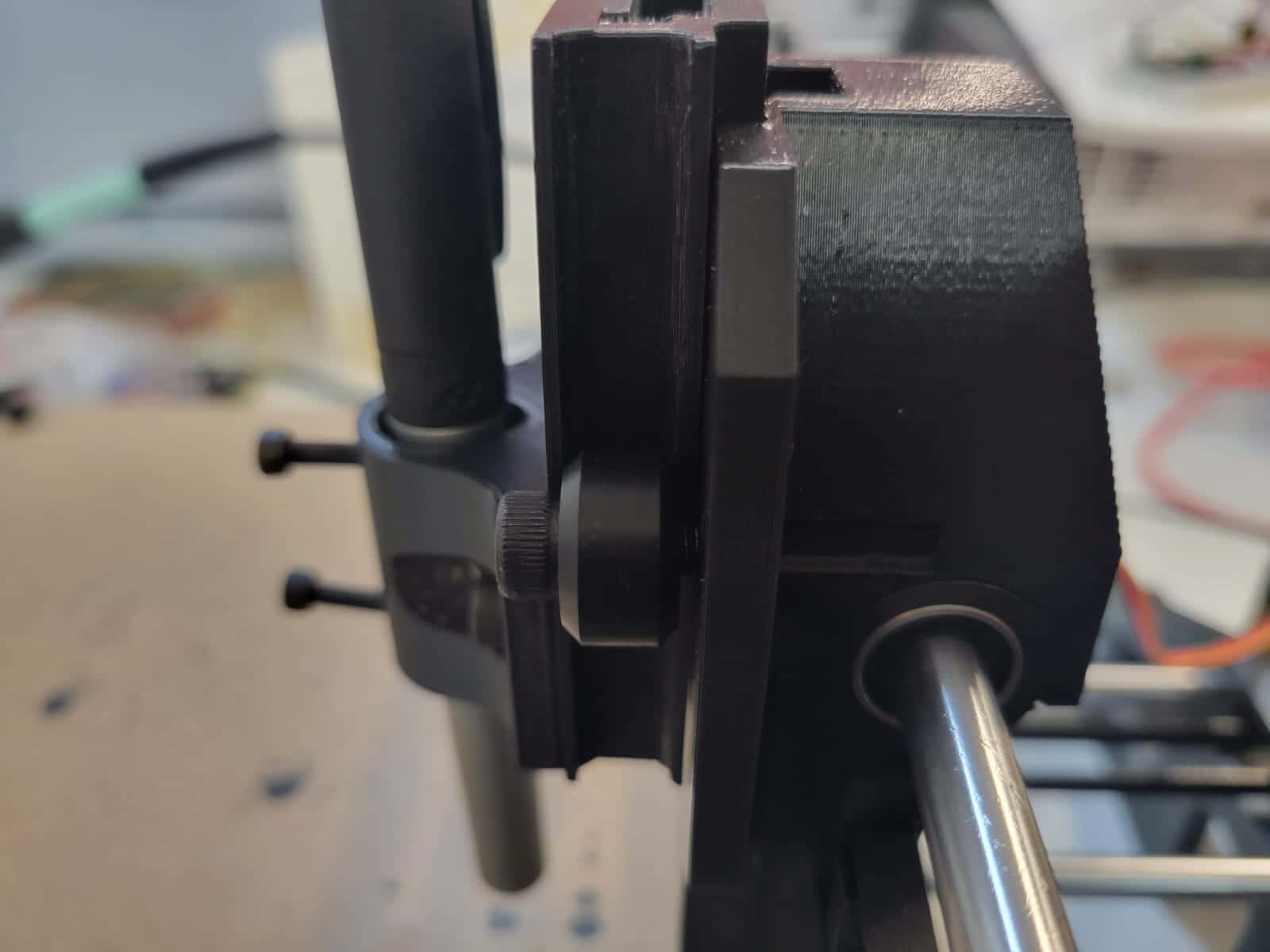
07_Y-Axis_Gantry Mount
This part holds the entire Y-axis as well as the motor.
08_Y-Axis_Pulley Mount
This is the part opposite of 07, it holds the pulley and acts as the limit of the Y-axis, additionally, it helps in keeping the axial rods straight and leveled.
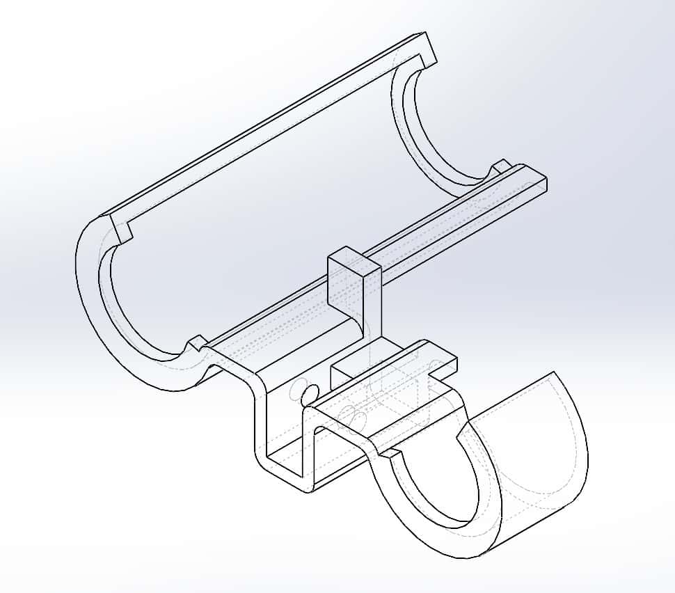
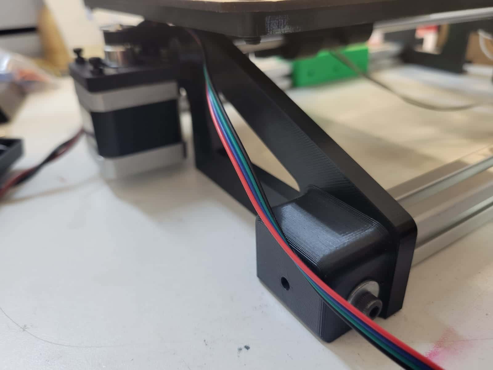
13_X-Axis_Bed Mount
This part was originally designed by my teammate Erwin, starting as a simple X shape that connects the axial carriage with the MDF bed. Eventually, we decided to make the part taller and add the rectangular braces to improve it's structural integrity.
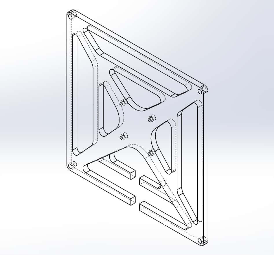
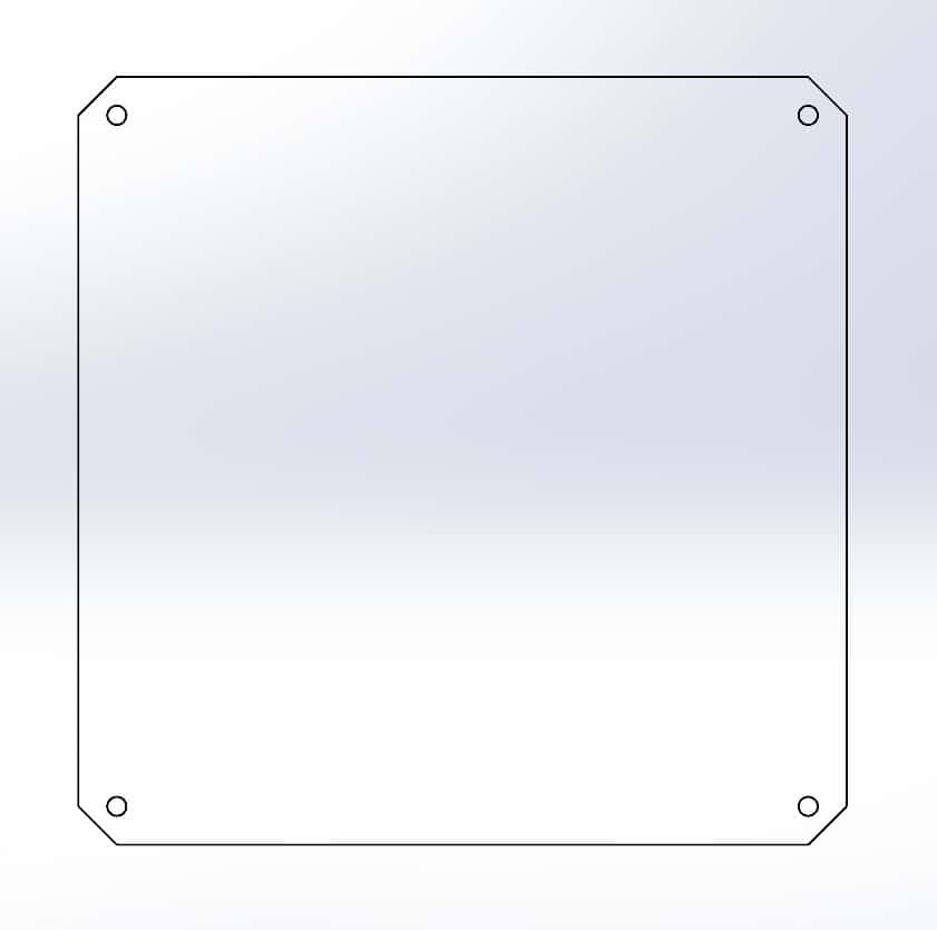
14_X-Axis_Bed_MDF
This is the bed over which we will be placing our drawing material. This part was cut out of 2.5mm thick MDF using the laser cutter.
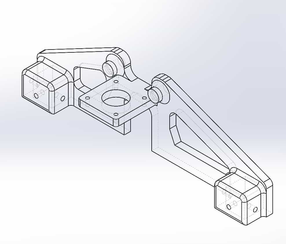
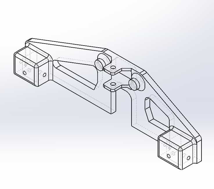
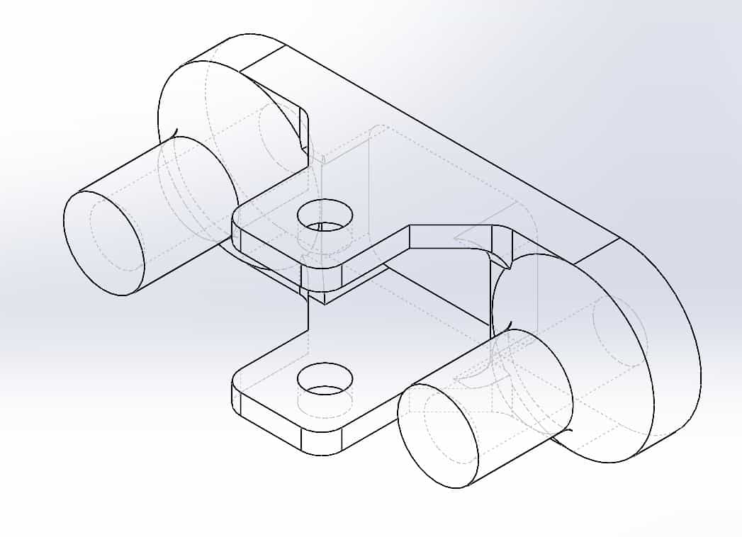
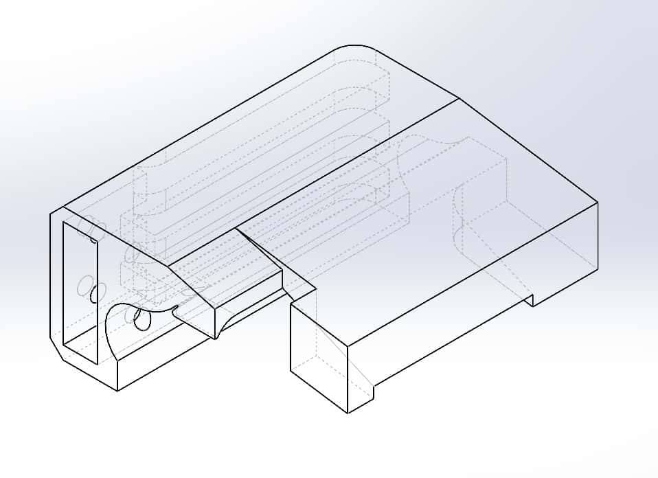
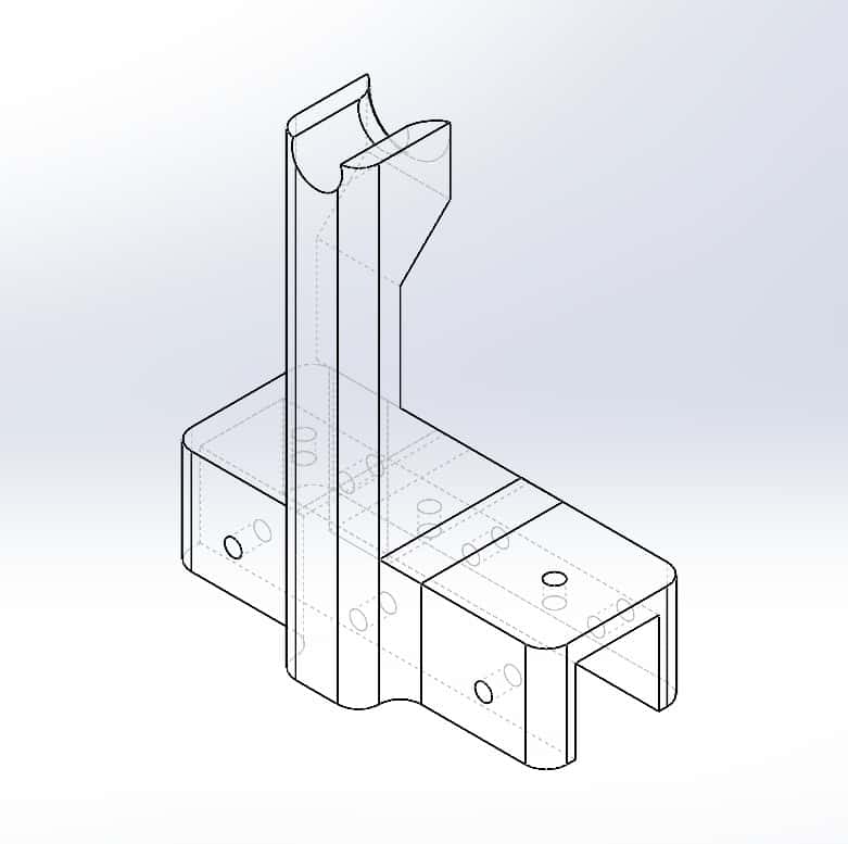
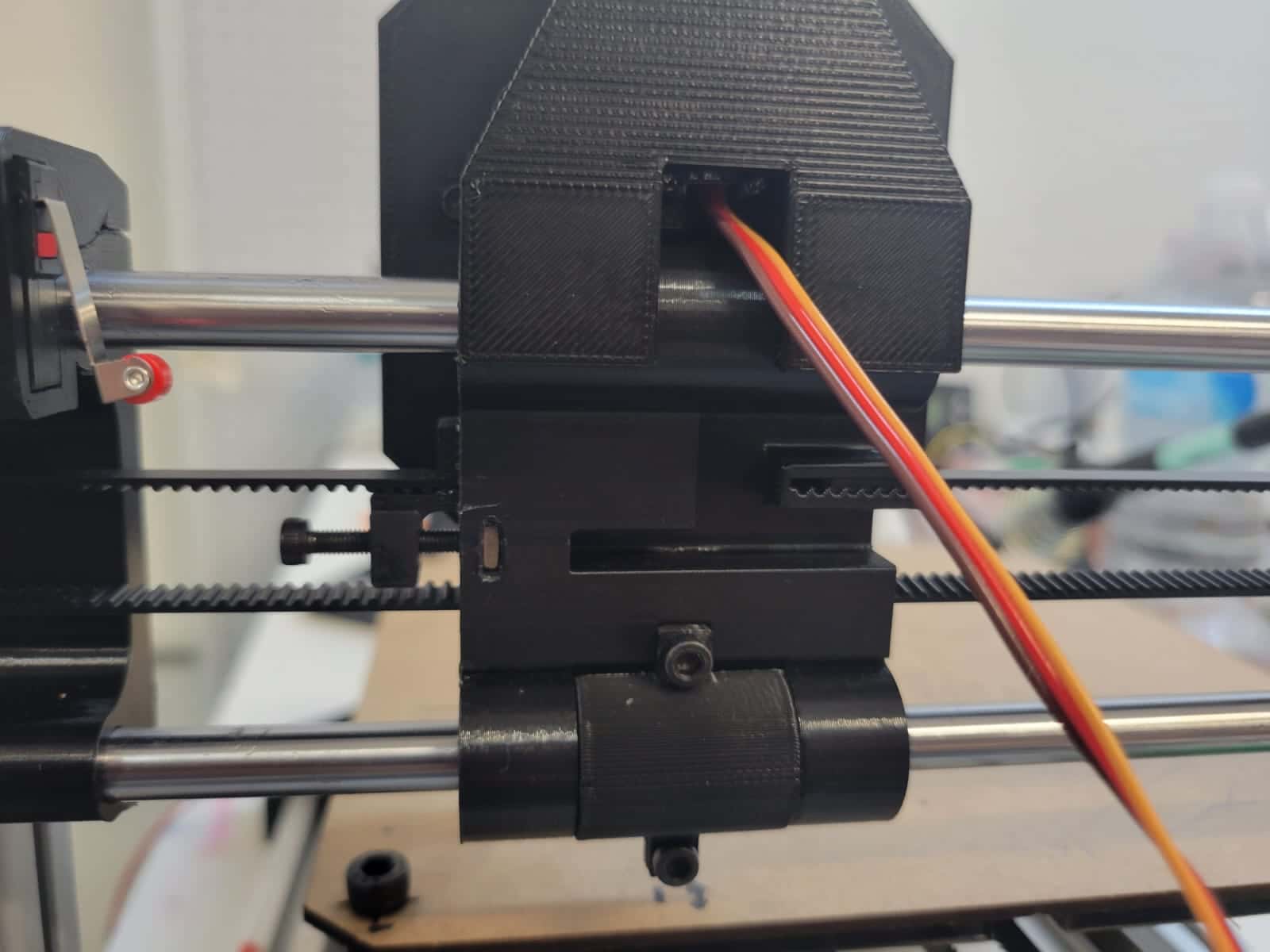
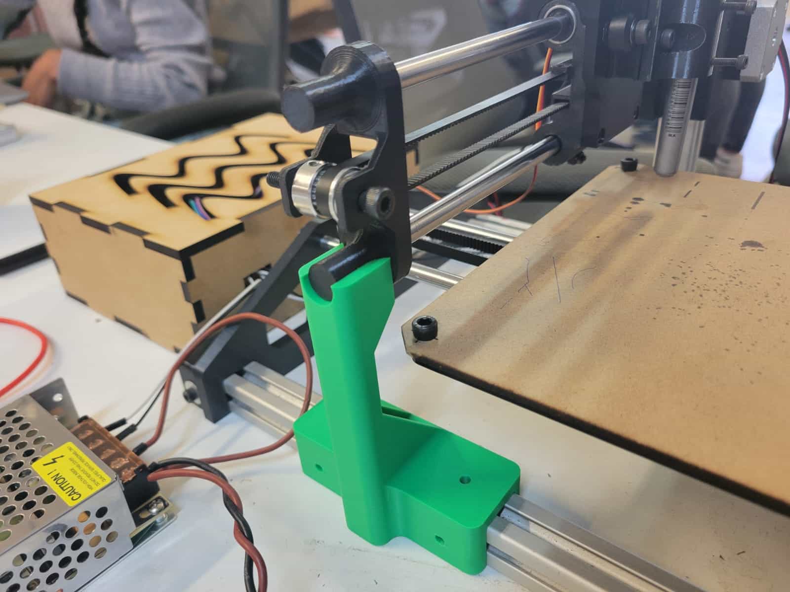
15_Y-Axis_Toolhead Mount
This was one of the most enjoyable parts to design, since I wanted to make it fit into the axial carriage using pressure. The part mates with the top of the carriage and is secured using screws. It's function is to hold the servomotor and act as a guide for the rack slider that will move our tool on the Z-axis.
18_Y-Axis_Limit Swith Mount
Once I figured out the right tolerances for making press-fits between the printed parts, I used this property to design the mounts for the endstop switches on both axes. For the Y-axis, the part is mounted on top of the gantry mount, holding the endstop switch on the back.
19_X-Axis_Limit Switch Mount
Same as before, I designed a part to hold the endstop switch and be able to press-fit onto the axial carriage.
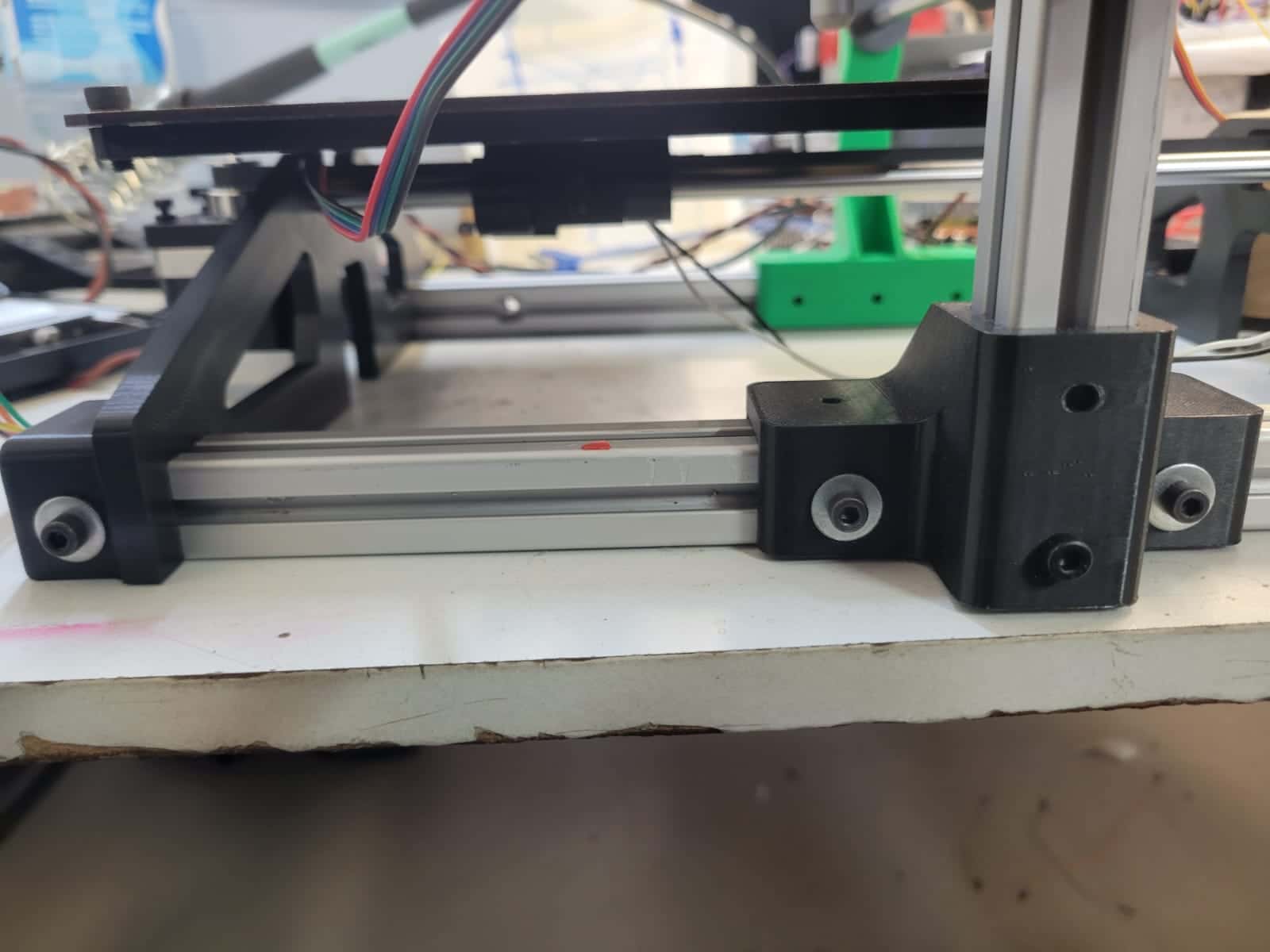
21_Y-Axis_Vertical Support Aid
This part is based on the perpendicular joint and mounts onto the V-slot profile, extending upward to reinforce the Y-axis gantry.
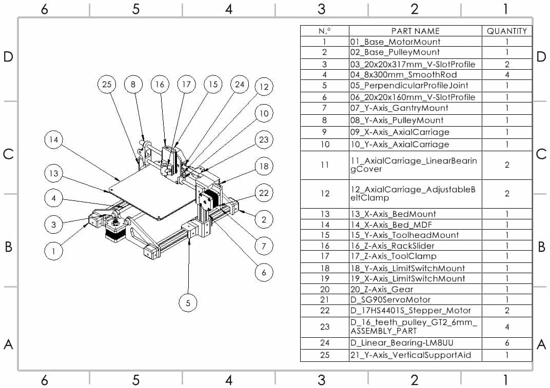
Parts 09, 10, 11 and 12 were designed by Erwin, and parts 16, 17 and 20 were designed by Joaquín. Four of the parts used in the assembly were downloaded from the internet, you can find the links to said parts near the bottom of this webpage.
3. Mechanical Systems
Our CNC plotter was designed with simplicity, modularity, and functionality in mind. The machine integrates two primary motion systems to achieve three-axis movement: a dual belt-driven system for the X and Y axes, and a rack-and-pinion mechanism for Z-axis actuation. Each was chosen based on accessibility of materials, ease of fabrication, and suitability for precise 2D plotting tasks.
3.1 Standardized Components
We used a variety of standardized components for various parts of the machine, these were;
- 20x20mm V-Slot profile - Two 317mm length, one 160mm length
- 8x300mm Smooth steel rods - Four units
- GT2 16 tooth pulley - Four units
- Nema 17 stepper motor - Two units
- 8mm interior Ø 24mm exterior Ø Linear Bearing - Six units
- 6mm tall Timing belt - Aproximately 1300mm
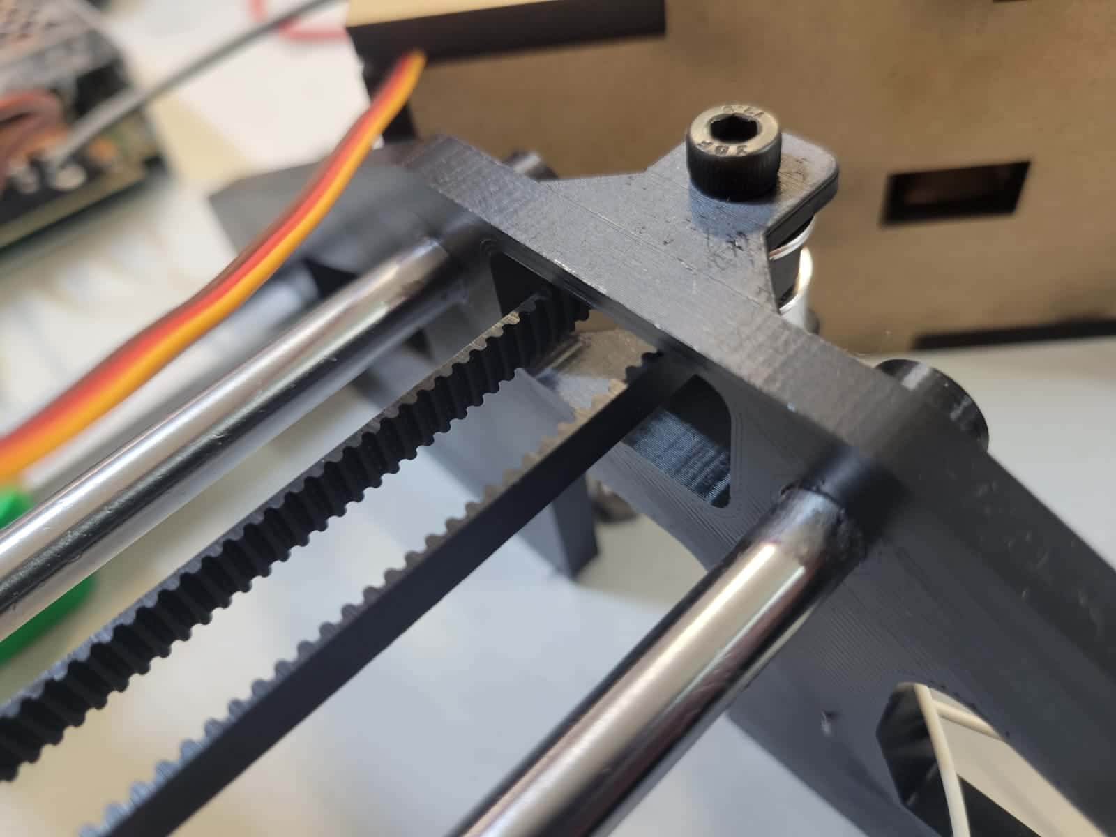
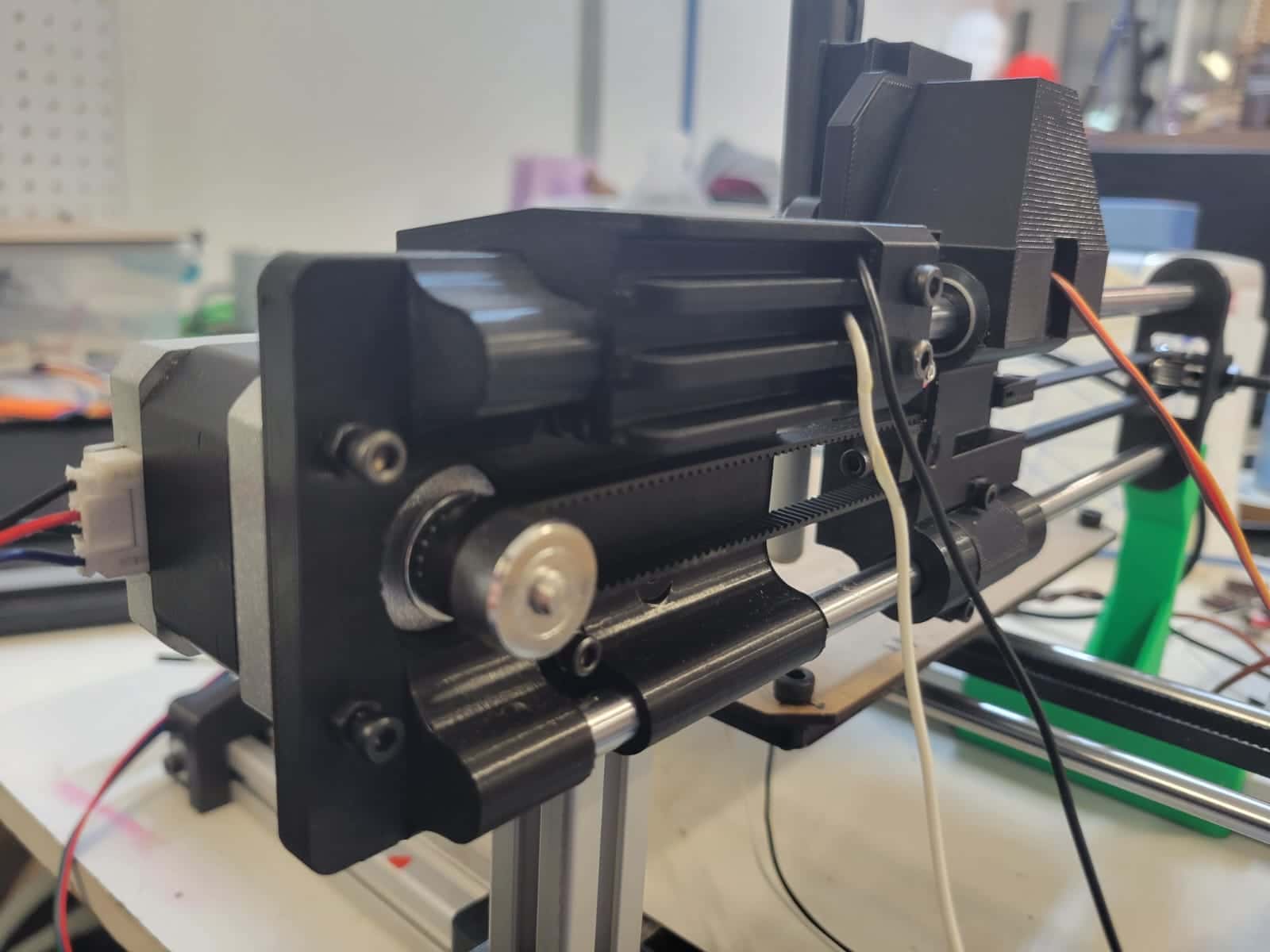
3.2 X and Y Axis: Belt-Driven Carriages
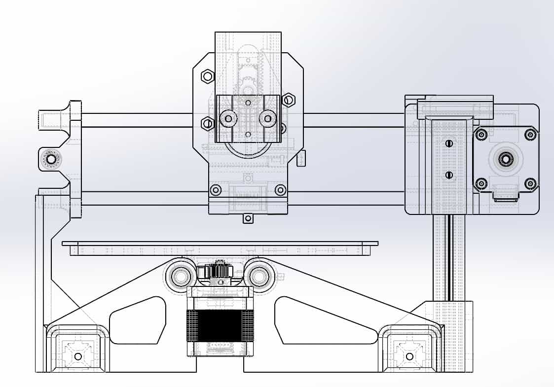
Both the X and Y axes utilize a belt-driven linear motion system mounted on smooth 8mm steel rods, guided by custom-designed axial carriages. Each axis is actuated by a NEMA 17 stepper motor coupled to a GT2 pulley system and tensioned with adjustable belt clamps. These belts translate rotational motion into linear movement, allowing the toolhead to navigate a defined workspace with high precision and low backlash.
The X axis moves the bed itself, sliding it along the horizontal direction, while the Y axis moves the toolhead across a perpendicular gantry. Both carriages are constrained using linear rods and custom-designed 3D printed bushings or mounts, ensuring smooth and controlled motion.
3.3 Z Axis: Rack and Pinion Actuation
The Z-axis motion is handled by a compact and reliable rack-and-pinion mechanism. This system is actuated by an SG90 servo motor mounted on the toolhead mount, which drives a small pinion gear. The gear engages with a vertically-oriented rack that raises or lowers a sliding tool holder, aided by three small guide wheels that ensure smooth, vertical alignment while minimizing friction and wobble..
This method was chosen for its mechanical simplicity, reduced weight, and suitability for short, precise vertical movements — ideal for a drawing tool. The up/down movement enables the machine to lift the drawing tool between strokes, making it fully capable of executing detailed G-code-based drawings.
4. Assembly Process
The assembly process was carefully planned and executed to ensure structural integrity, smooth motion, and precise alignment across all axes. Most components were 3D printed using standard settings with 15% infill, balancing strength and print efficiency. The 20x20 mm V-slot aluminum profiles were cut to size using a horizontal, floor-mounted bandsaw, ensuring clean and accurate cuts for a stable frame.
Many of the printed parts were designed to press-fit into the V-slot profiles and the 8 mm smooth rods, minimizing the need for fasteners while ensuring a snug and aligned fit. We began the assembly with the axial carriages, inserting linear bearings and sliding them onto the smooth rods. Once aligned, the rods were secured into their respective mounts at each end of the frame.
Next, we assembled the base frame using the V-slot profiles, aligning them at the corners and drilling through the joints to fix them with M4 screws. This provided a solid foundation for the rest of the machine. The NEMA 17 stepper motors and GT2 pulley systems were mounted with a focus on leveling and alignment. Once fixed in position, their height and spacing were carefully adjusted to ensure minimal resistance and smooth belt motion. The belts were then looped around the pulleys and secured using our custom-designed belt clamp system, allowing for precise tensioning.
Certain components, such as the toolhead mount and the endstop switch mounts for both axes, were designed to press-fit directly into other 3D printed parts. The toolhead mount, which holds the servo and guides the Z-axis rack, is also secured to the Y-axis carriage using M3 screws for added stability.
The rack-and-pinion mechanism of the Z-axis is connected to the toolhead mount through the gear and the servo, and fits into a slot on the toolhead mount to aid in guiding the linear movement. Additionally, we installed three small wheels using M5 screws, to aid in movement and stability.
5. Motion Testing and Calibration
Once the mechanical assembly was complete, we proceeded with motion testing for all three axes. The results were highly satisfying — each motion system performed reliably and smoothly, with only minimal adjustments required during the testing phase.
The X and Y axes, driven by GT2 belts and NEMA 17 stepper motors, demonstrated precise, responsive movement. Minor tension adjustments were needed to fine-tune the belt tightness and eliminate subtle vibrations or slack. These corrections were easily implemented using the built-in tensioning features of our belt clamp designs.
The Z axis, actuated via the rack-and-pinion mechanism controlled by an SG90 servo motor, also functioned as intended. Initially, however, we encountered significant wobble during the up-and-down motion. This resulted in noticeable vibrations and flaws in the plotted output, particularly during pen lifts and drops. To resolve this, we carefully adjusted the position of the guide wheels, increasing their pressure against the sliding rack to reduce lateral play. We also slightly tightened the rack within its channel and reinforced the alignment of the vertical guide system. These refinements drastically improved Z-axis stability, eliminating unwanted vibrations and restoring consistent vertical movement.
During early testing, we also identified a structural flaw in the support of the Y axis. It was originally mounted solely on the gantry mount, which itself was fixed to a 160 mm 20x20 V-slot profile. However, the weight of the Y axis caused a slight downward deflection on the unsupported side, resulting in a small tilt. To resolve this, I designed and fabricated a custom support bracket for the opposite end of the axis. Once installed, the new part successfully restored balance and alignment to the entire system, ensuring smooth and level motion across the Y axis.
6. Plotting Process and Results
To evaluate the final performance of our machine, we ran a series of test plots using G-code generated from vector files. The process involved sending the code wirelessly from a computer to the microcontroller, which interpreted the data and moved the pen across the X, Y, and Z axes.
The results were highly encouraging — the machine executed detailed line drawings with good repeatability. Adjustments made during calibration, particularly to the belt tension and Z-axis stability, significantly improved drawing consistency and accuracy. We observed minimal wobble and smooth transitions between stroke paths.
7. Comments and Recommendations
This was without a doubt the most challenging assignment I've faced during Fab Academy, and perhaps in my academic journey so far. It demanded the integration of nearly every skill we've developed so far: mechanical design, electronic systems, programming, collaboration, and time management.
Building a functional CNC machine from scratch is a deeply rewarding experience, but it also requires considerable planning, iteration, and teamwork. I strongly recommend future students to start early, distribute responsibilities according to each member's strengths, and maintain clear communication throughout the process. The more you test and iterate, the more satisfying the final result will be.
8. Learning Outcomes
This week was a powerful example of multidisciplinary collaboration in action. As a team, we designed and built a fully functional CNC plotting machine, from mechanical structure to motion control and software integration. It reinforced how vital it is to approach complex systems holistically: every design decision, component choice, and line of code plays a role in the machine's performance.
Through this experience, I gained a deeper appreciation for the interplay between digital design, fabrication, and embedded control. It's a reminder of how much we can accomplish when we combine skills, communicate effectively, and iterate with intention.
Useful Links
- GrabCAD Linear Bearing Model
- GrabCAD Nema 17 Stepper Motor Model
- GrabCAD GT2 Pulley Model
- GrabCAD SG90 Servo Motor Model