Group 1: FAST TRACER
Individual Assignments


VIDEO AND RESULTS
INDIVIDUAL CONTRIBUTIONS
- Structural Design - José Carlos Matanzo
- Axial Carriage Design and Programming - Erwin Vivar
- Toolhead Design - Joaquín Gómez
- Main PCB and MDF box design - Adriana Mexicano
- Relay PCB design - Emmanuel Ángeles
1. Machine Concept
For this assignment, our team set out to design and build a CNC plotter which is a machine capable of drawing precise vector designs onto a surface by interpreting G-code instructions. A CNC plotter works by translating digital coordinates into physical movement using motors and mechanical components, making it an excellent project to explore the fundamentals of motion control, fabrication, and automation.
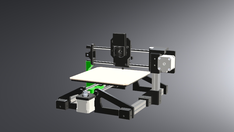
We chose this machine concept because it strikes a balance between mechanical simplicity and the opportunity to implement advanced control systems. It involves core aspects of digital fabrication: structure design, actuation mechanisms, electronics, and programming.
2. Mechanical Materials
| Quantity | Component | Value / Model | Description |
|---|---|---|---|
| 2 | Aluminum Profile | 20x20x317 mm | Main horizontal frame structure |
| 1 | Aluminum Profile | 20x20x160 mm | Vertical gantry support |
| 4 | Smooth Steel Rods | 8x300 mm | Linear motion guides |
| 6 | Linear Bearings | LM8UU | For smooth sliding along rods |
| 4 | Pulleys | GT2 16T | Used with timing belt on motors |
| ~1300 mm | Timing Belt | GT2 | Belt for X and Y axis motion |
| 1 | Material Sheet | 400 mm² MDF | Laser-cut machine bed |
| - | Filament | PLA | Used to 3D print all plastic parts |
| 3 | V-Slot Wheels | 15 mm | Used to stabilize Z-axis toolhead |
| 25 | Screws | M3 | Various fasteners used throughout the entire system |
| 9 | Screws | M4 | Various fasteners used on the V-slot profiles and toolhead |
| 9 | Screws | M5 | Various fasteners used on the bed, toolhead and pulley mounts. |
| 12 | Washers | M4 | Used on the M4 screws that secure the V-slot profiles. |
3. Electronic Materials
| Quantity | Component | Value / Model | Description |
|---|---|---|---|
| 1 | Microcontroller | XIAO RP2040 | Main microcontroller |
| 2 | Motor Driver | A4988 | Stepper motor driver |
| 1 | Voltage Regulator | L7805 | 5V voltage converter |
| 2 | Electrolytic Capacitor | 100 μF | Power filtering |
| 1 | Electrolytic Capacitor | 10 μF | Regulator input capacitor |
| 1 | Electrolytic Capacitor | 22 μF | Regulator output capacitor |
| 2 | Resistor | 1 kΩ | Pull-down for endstops |
| 3 | Connector | Header | Motor outputs |
| 1 | Connector | Header | Buzzer |
| 2 | Connector | Header | Endstop inputs |
| 1 | Connector | Header | Z-axis servo |
| 2 | Connector | Header | Endstops 1 and 2 |
| 1 | Connector | Header | OLED display |
| 1 | Connector | Header | Extra pin |
| 1 | Connector | Header | Common GND |
| 2 | Stepper Motor | NEMA 17 | Drives X and Y axis |
| 1 | Servo Motor | SG90 | Controls Z-axis movement |
| 1 | Relay Module | K1 Relay | General-purpose relay |
| 1 | Optocoupler | - | Signal isolation |
| 1 | NPN Transistor | - | Signal amplification/switching |
| 2 | Endstop Switch | - | Contact sensor |
4. Mechanical Design Process
4.1 Structural Design
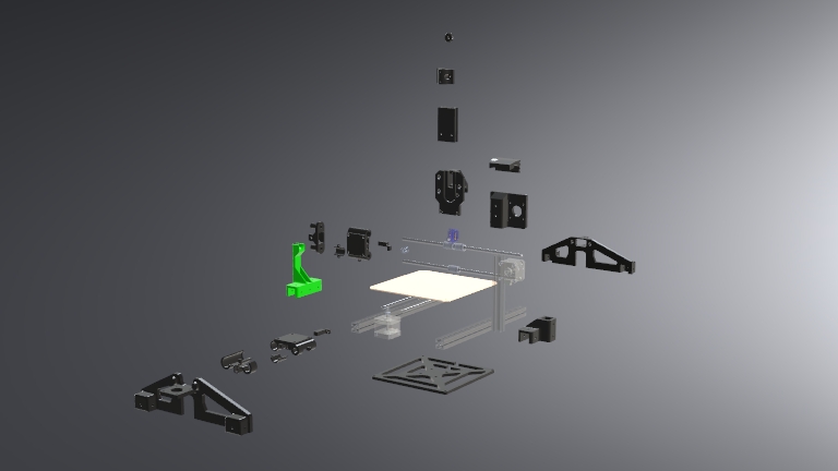
The structural design of our CNC plotter was driven by one core constraint: the 8x300 mm smooth steel rods used for linear motion. These rods were the first components chosen for the build, and we decided early on not to cut or modify them — instead, we designed the rest of the machine around their fixed dimensions.
 The first components created were the base parts that hold these rods and support the bed movement. These initial designs established the overall scale of the machine and influenced the dimensions of all other structural elements.
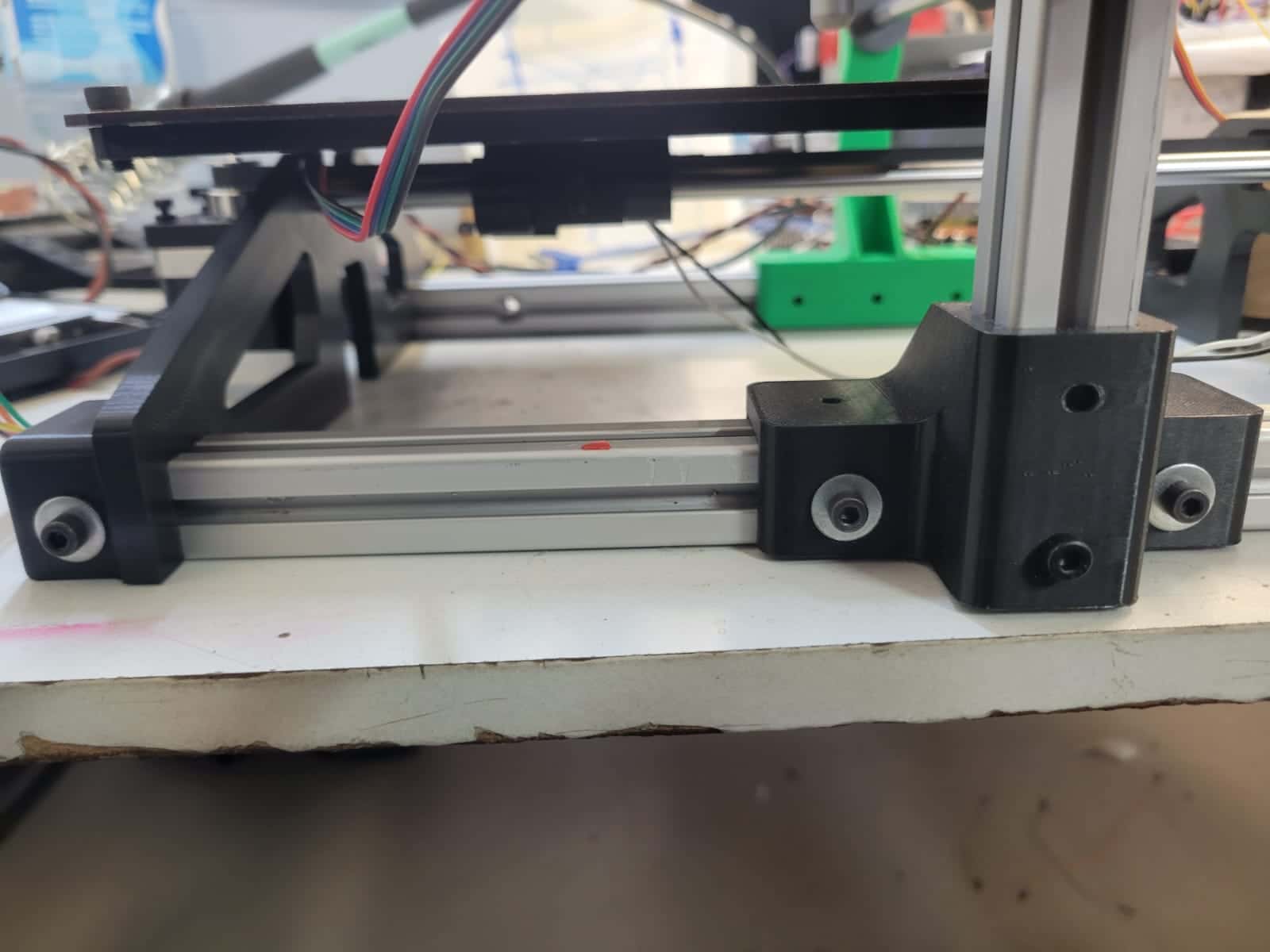
To provide a strong foundation, we integrated two 20x20 mm V-slot aluminum profiles along the sides. These profiles increased surface stability and allowed us to begin building vertically, where we added the gantry system. To hold the vertical structure, we designed a perpendicular joint that connects the vertical V-slot to the base.
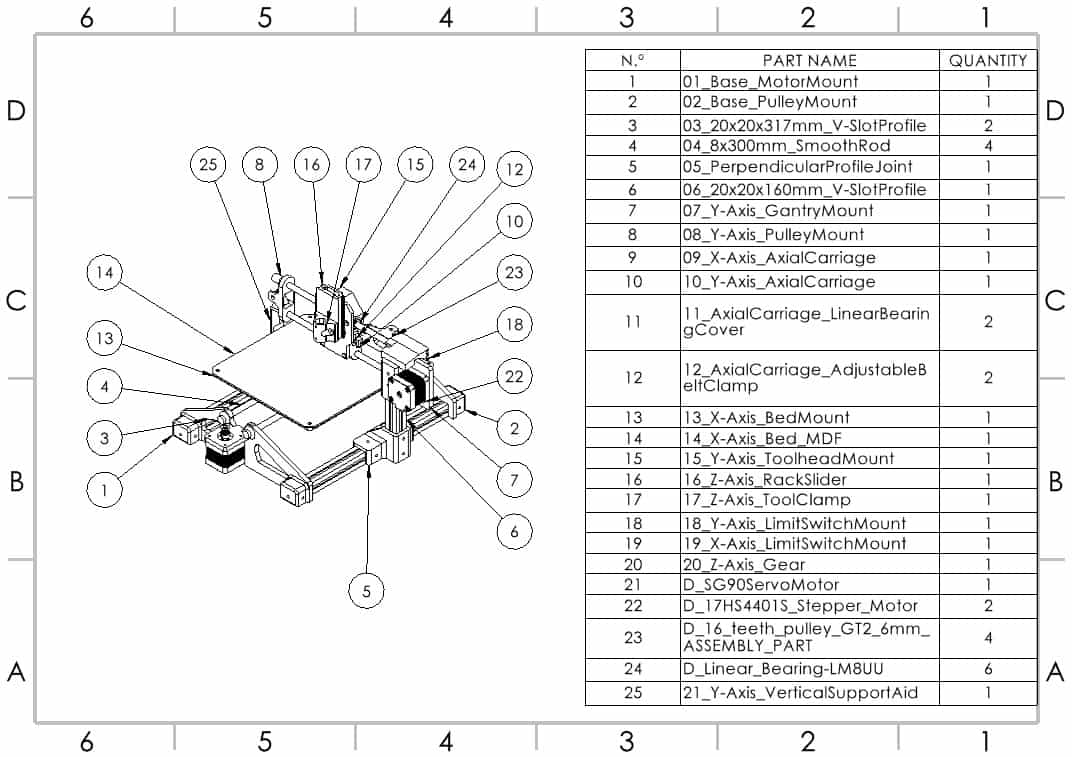
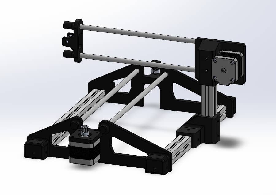
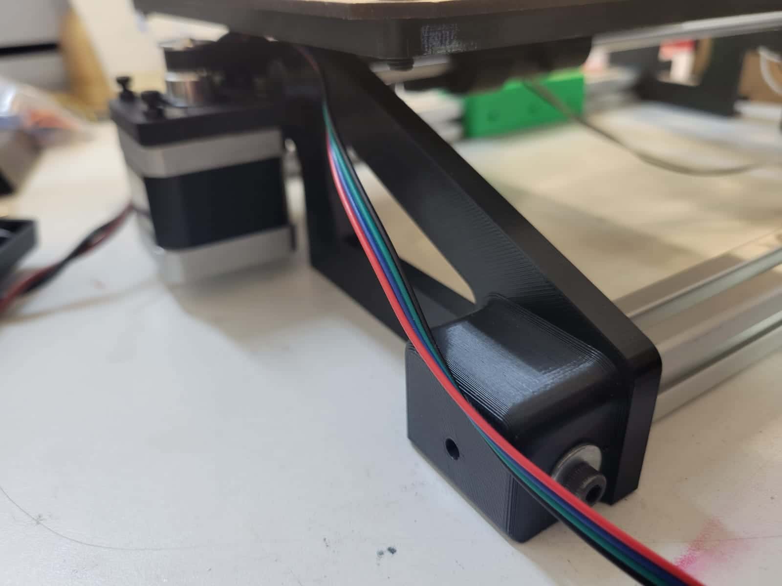
On top of this structure, we mounted the Y-axis gantry system, beginning with a motor mount that also secures the 8 mm rods in place. Opposite to it, a mirrored pulley mount was installed to hold the tensioning system and the second end of the rods.
We also designed custom mounts for both the X and Y-axis endstop switches. These were press-fit parts that integrated easily into the system without requiring additional fasteners, simplifying the build process.
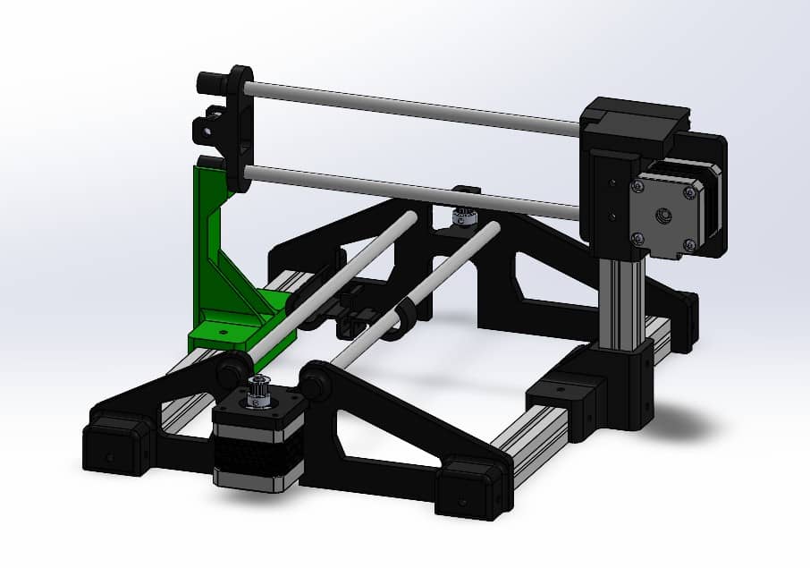 Finally, after noticing a slight sag on the unsupported side of the gantry due to the weight of the rods and the toolhead, we designed a support aid (highlighted in green in the render) that reinforces the vertical alignment of the structure. This addition helped maintain consistent belt tension and parallel motion across the axis.
You may find more detailed information on the structural design in Carlos's individual assignment.
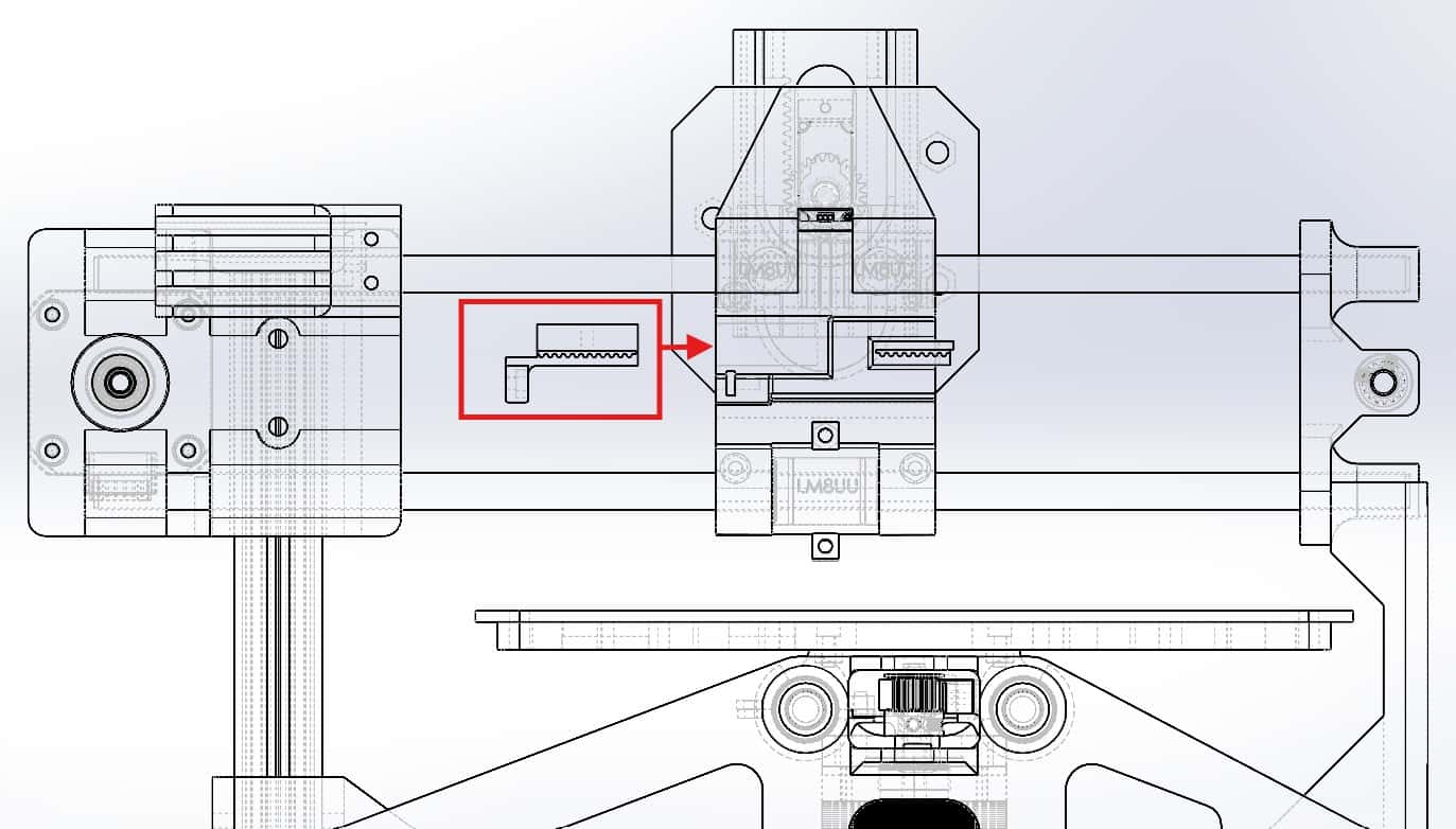
4.2 Axial Mechanism Design
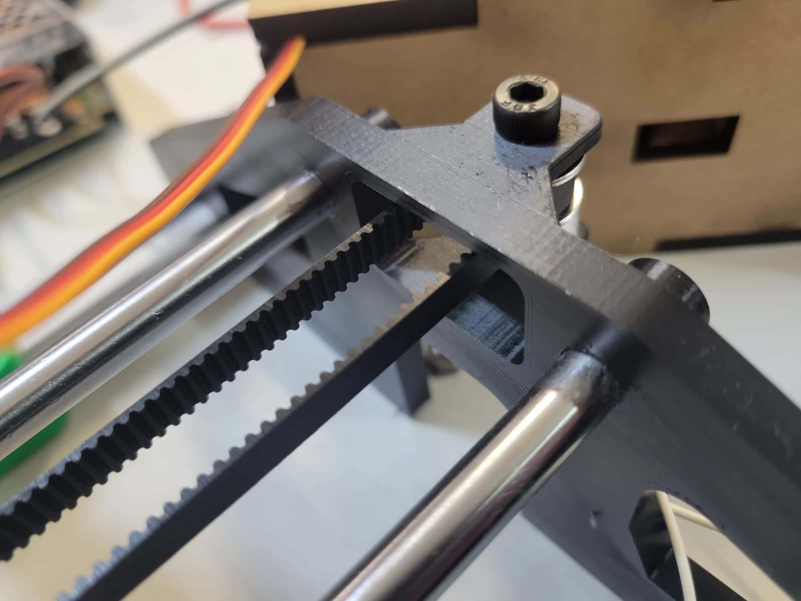
The axial motion of our CNC plotter is driven by two carriages — one for the X-axis (bed) and one for the Y-axis (toolhead). Both carriages were designed with a flat surface to allow for easy and secure mounting of other components. Each includes press-fit holes to house LM8UU linear bearings, allowing for smooth movement along the 8 mm steel rails.
One of the standout features of the design is the belt tensioning mechanism integrated into each carriage. On one side, a toothed slot securely grips the GT2 timing belt. The belt loops around the drive pulley, continues through a guide hole, and wraps around the opposite pulley. At the return side, the belt is fed into a custom 3D-printed clamp.
You may find more detailed information on the axial mechanism design in Erwin's individual assignment.
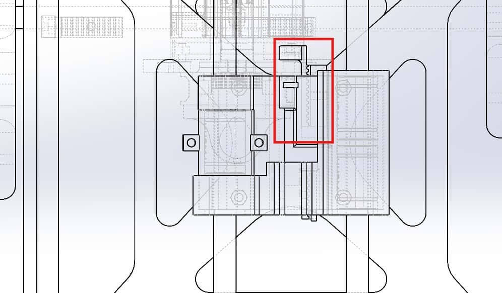
4.3 Toolhead Design
The toolhead is mounted directly above the Y-axis carriage, combining press-fit and screw fixation to ensure stability during operation. The main toolhead mount holds an SG90 servo motor positioned at the top, which drives a small gear that engages with a vertically mounted rack.
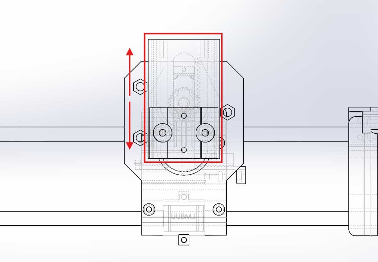 The rack is integrated into a sliding component that moves up and down based on the servo's rotation. This rack-and-pinion mechanism provides controlled Z-axis movement, allowing the pen or tool to be raised and lowered between drawing paths.
To ensure smooth motion and prevent wobbling, the sliding toolhead is guided through a vertical slot integrated into the mount. Additionally, three 15 mm bearing wheels are strategically positioned to add lateral stability and minimize vibrations. This stabilization proved to be a critical factor in improving the plot quality, especially during complex linework and high-speed movements.
You may find more detailed information on the toolhead in Joaquín's individual assignment.
5. Production and Assembly
Most custom components for the machine were 3D printed using PLA. We used PrusaSlicer with default print parameters, adjusting the infill between 10% and 15% depending on the part's mechanical load. Notably, we extensively used rafts for large or complex parts — this strategy significantly reduced the chances of print warping or detachment from the bed, an issue faced by other teams.
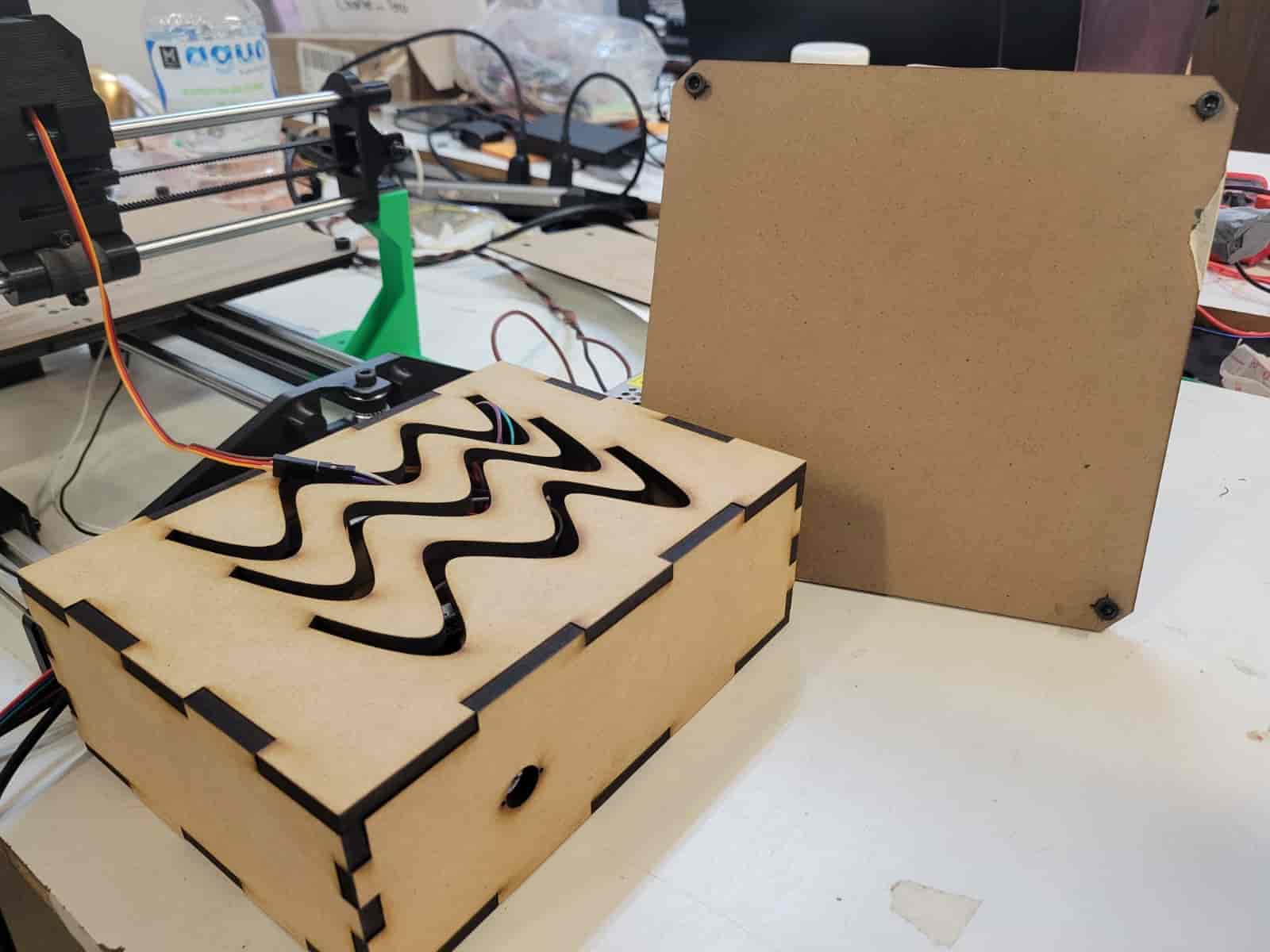
The machine bed and a separate electronics box (non-structural) were laser cut from MDF, allowing for quick and clean fabrication. For the frame, V-slot aluminum profiles were precisely cut using a floor-mounted bandsaw, which ensured high accuracy and clean edges necessary for reliable structural assembly.
Many assemblies were achieved through precise press-fit designs, especially between 3D printed parts and the endstop switch mounts. Where additional strength was needed, screws were used strategically:
- M4 screws — for mounting 3D printed parts to the V-slot profiles
- M3 screws — for general 3D part assembly and securing the NEMA 17 motors
- M5 screws — for mounting the bed, the GT2 pulleys, and the bearing wheels
Overall, the modular design and thoughtful material selection allowed for a smooth production process and a robust, cleanly assembled final structure.
6. Electronics Design and Production
6.1 Electronics Design
The custom electronics system for our machine consists of a microcontroller-based PCB responsible for coordinating movement across all three axes. The X and Y axes are controlled via stepper motor drivers, while the Z axis is actuated by a servo motor (SG90). Power is supplied via a 12V external power source. A voltage regulator circuit steps down the voltage from 12V to 5V, ensuring the servo receives the appropriate operating voltage.
To manage the activation of the motors, a relay system was integrated into the PCB. This setup allows current to be switched with control logic, providing added protection and control over motor actuation.
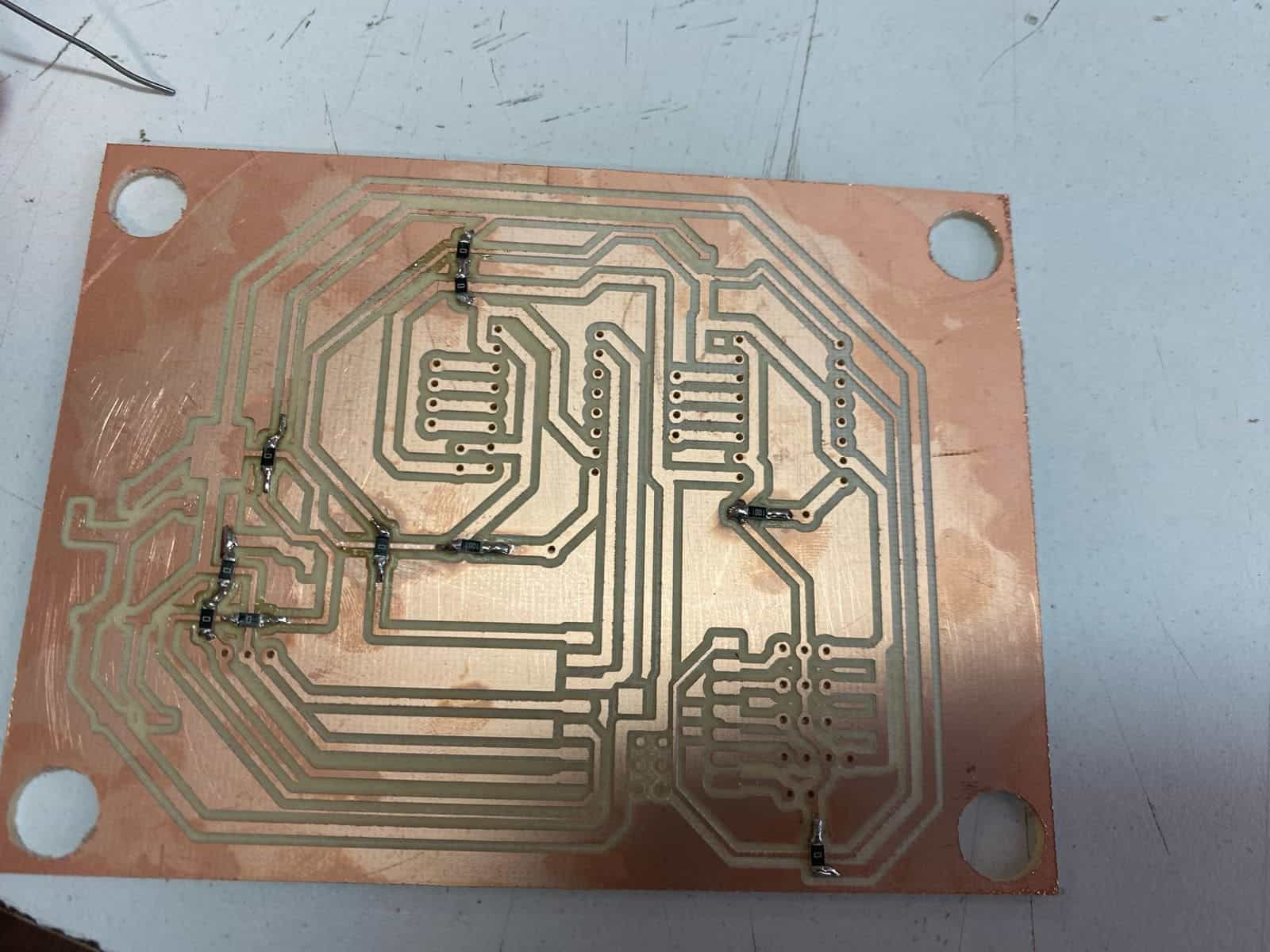
6.2 PCB Design and Fabrication
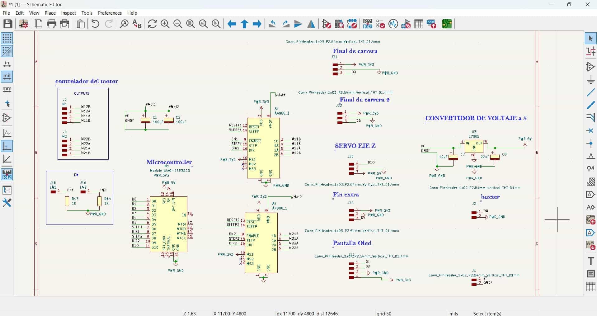
- Schematic Design: We used KiCad to create the schematic, adding components including the Seeed XIAO microcontroller, drivers, voltage regulators, relay, connectors, and headers.
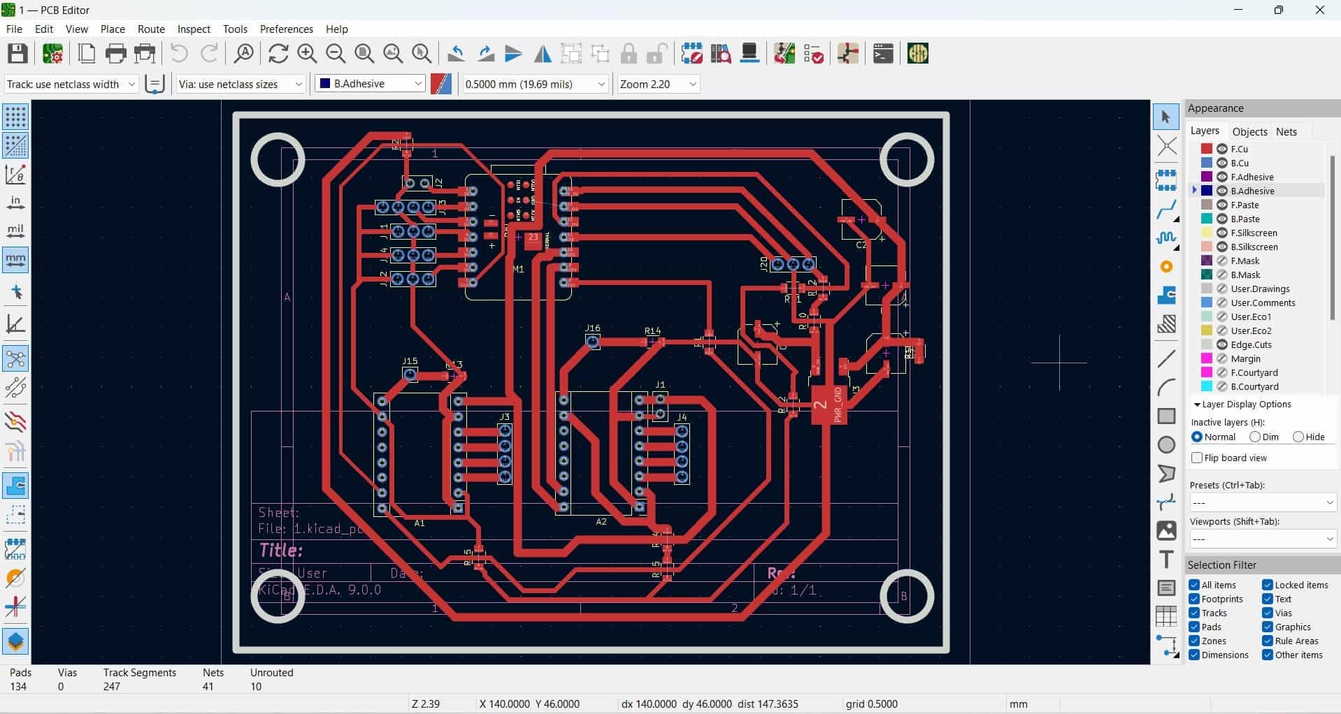
- PCB Layout and Routing: Once the schematic was complete, the PCB layout was arranged. To address crossover traces on a single-layer board, we employed 0-ohm resistors as jumpers, a common strategy to avoid vias or dual-layer complexity.
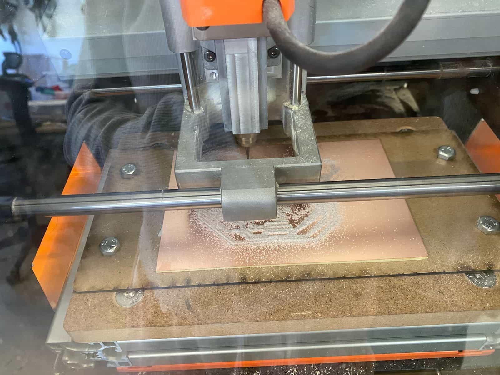
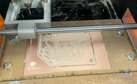
- PCB Manufacturing: Using the Roland SRM-20 MonoFab, we milled the board in three stages:
- Drilling holes for through-hole components,
- Milling the copper traces,
- Cutting the board outline.
- Soldering: The components were soldered manually, following good soldering practices — starting with small passive components like resistors and 0-ohm jumpers, and finishing with headers and large components.
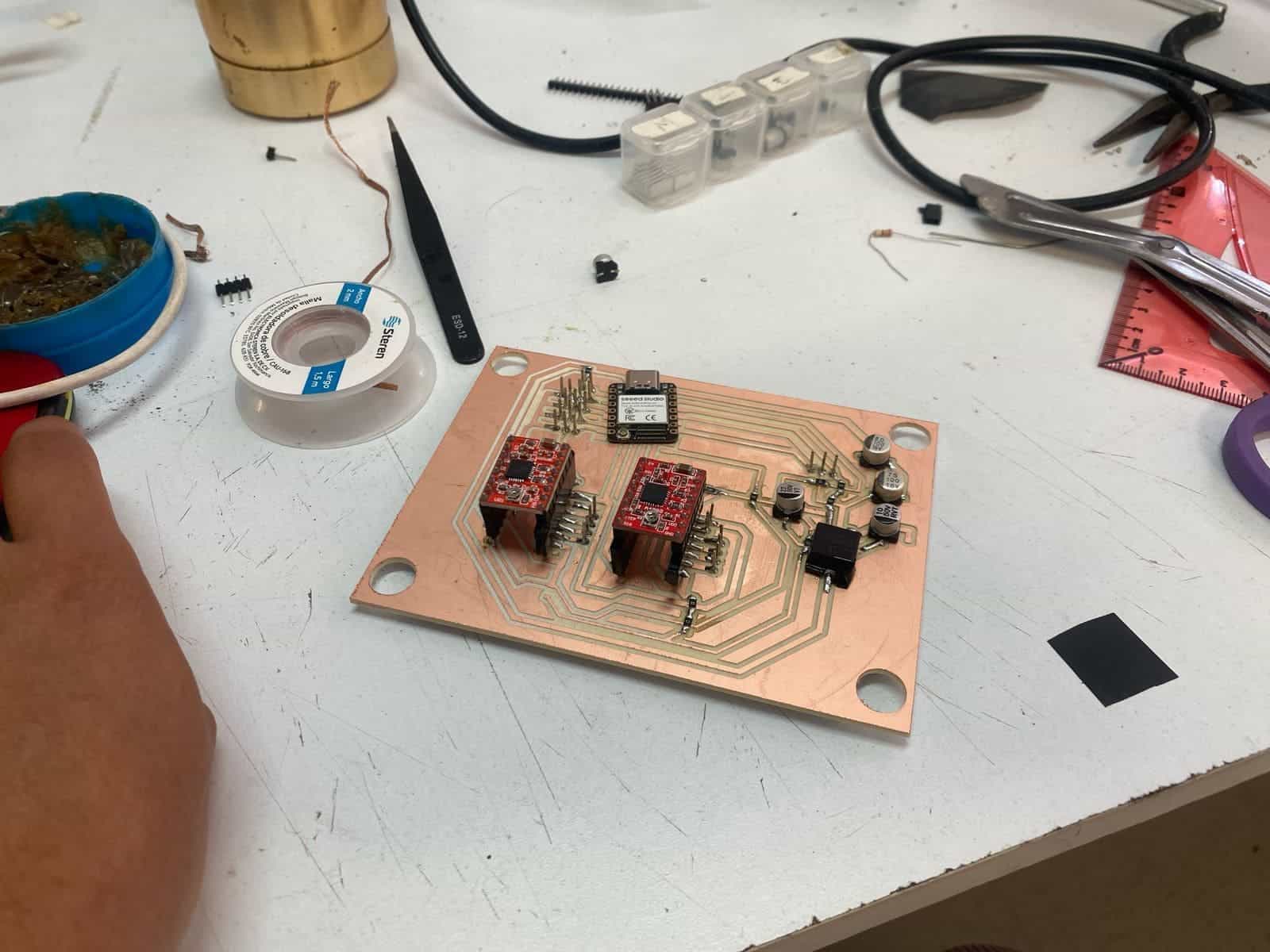
The PCB also includes connectors for optional peripherals: an LCD display to indicate the current machine status, and a buzzer to signal process completion. While these were included in the design, they were not necessary during operation since the machine's status can be directly observed.
You may find more detailed information on the main PCB's design and production in Adriana's individual assignment.
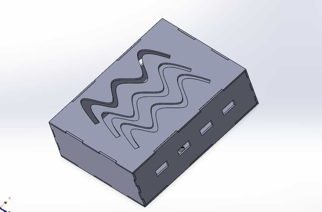
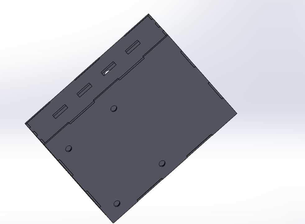
6.3 PCB Case Design
A custom protective case for the PCB was designed in SolidWorks. It includes side cutouts for cable access and ventilation openings on the top for passive airflow. The case provides protection from accidental damage and helps with cable management.
The case was designed by Adriana and fabricated by Joaquín
6.4 Troubleshooting and Lessons Learned
One key issue encountered was related to powering the microcontroller. The Seeed XIAO does not feature a built-in switch to choose between USB and external power sources. During initial testing, power was unintentionally supplied through both the USB and the external 5V regulator, causing the microcontroller to fail.
Fortunately, the rest of the PCB remained functional. We replaced the damaged XIAO and implemented a fix: cutting the 5V line from the regulator to the XIAO, allowing it to be powered solely by USB when connected to a computer. This solution prevented further power conflicts and ensured stable operation.
6.1 Safety Relay Circuit Design
As an added safety measure, our team designed and fabricated a small custom PCB dedicated to separate the logic and power supply, which is essential when controlling high-power components, like motors, using a microcontroller, such as the Xiao RP2040. This separation ensures that the microcontroller is powered on first before the motors, preventing damage from excessive power draw. This board integrates an optocoupler, a transistor, and a relay, acting as an electrically-isolated switch between the microcontroller and high-power components.
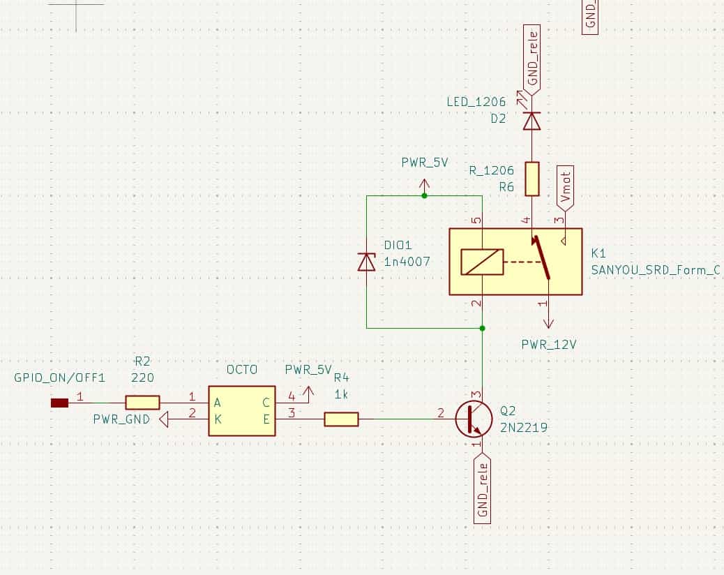
Optocoupler
An optocoupler is used to isolate the low-power logic side from the high-power motor side. In this configuration, the optocoupler's LED is activated by a signal from the microcontroller. The LED's light triggers the phototransistor on the output side, allowing the signal to pass while maintaining electrical isolation between the two sections.
Mode of Operation:
The optocoupler operates in phototransistor mode. When the LED inside the optocoupler is turned on, it closes the circuit by activating the phototransistor. This allows the control signal to pass through while isolating the high-power components from the microcontroller.
Optocoupler Connections
- Input Side (Pins 1-2): The LED inside the optocoupler
- Pin 1 (Anode) is connected to
GPIO_ON/OFF1through a 220Ω resistor (R2) - Pin 2 (Cathode) is connected to
PWR_GND - Output Side (Pins 3-4): The phaototransistor
- Pin 4 (Collector) is connected to
PWR_5V - Pin 3 (Emitter) is connected to the base of transistor
Q2through a 1kΩ resistor (R4)
2N2222 NPN Transistor
The 2N2222 NPN transistor acts as a switch to control the relay coil. When the optocoupler's phototransistor is activated, it provides current to the base of the 2N2222, allowing it to conduct and energize the relay coil.
Mode of Operation:
The transistor is in saturation mode. When the base-emitter junction receives sufficient current from the optocoupler, the transistor allows current to flow from the collector to the emitter, thus activating the relay. The transistor essentially switches the high-power relay without being directly connected to the microcontroller.
Base Resistor (R4):
The resistor limits the current to the base, preventing excessive current flow that could damage the transistor.
Relay (K1)
A relay is used to switch the high-power components, such as motors, in the CNC. When the relay is activated, it closes the contacts, allowing power to flow to the motors.
Relay Connections
- Coil (Pins 1-2):
- Pin 1 is connected to
GND_relay - Pin 2 is connected to a diode (
D101) and to the collector of transistorQ2 - Switching Contacts (Pins 3-4-5):
- Pin 3 is connected to
Vmot(motor voltage) - Pin 4 is connected to
PWR_12V - Pin 5 is connected to
PWR_5Vthrough a resistor (R6)
Why a Relay?:
Relays handle higher current than the microcontroller, allowing the microcontroller to control the motor's power without directly supplying the high current, which it can't provide.
Flyback Diode (D1)
The flyback diode is placed in parallel with the relay coil. When the relay is de-energized, the inductive load generates a voltage spike. The diode provides a path for the current to dissipate safely, protecting the transistor from potential damage caused by the back electromotive force (EMF).
Purpose:
The flyback diode absorbs the voltage spike when the relay is turned off, preventing damage to the transistor and other components.
Circuit Operation Summary
When GPIO_ON/OFF1 outputs a HIGH signal, it turns on the LED inside the optocoupler. The phototransistor inside then conducts, sending current to the base of the NPN transistor Q2. This activates Q2, which energizes the relay's coil, switching the relay's contacts from the default (normally open or closed) to the active position. This mechanism allows safe and controlled power delivery to the stepper motor drivers.
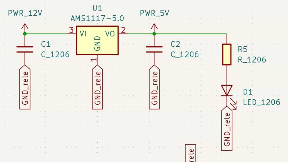
Other additions to the board
Additionally, the board is equipped with an AMS1117 5V voltage regulator. This was necessary because the relay available to us could only be powered with 5V. Therefore, we needed to step down the 12V input from the power supply to 5V to ensure proper operation of the circuit.
The board also includes pull-up resistors for the CNC endstops. Initially, we intended to use endstop modules; however, we were unable to obtain them in the required format and instead acquired individual switches. With the pull-up resistors in place, the Xiao RP2040 is able to interpret signals from the endstops effectively.
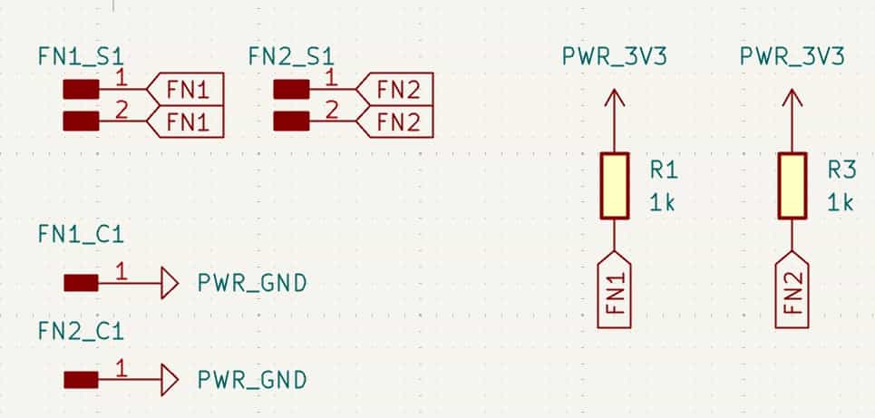
Here, you can find both the complete schematic and the PCB design with their respective connections.
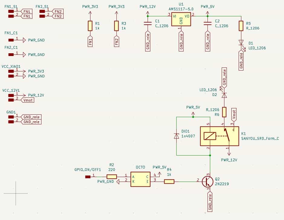
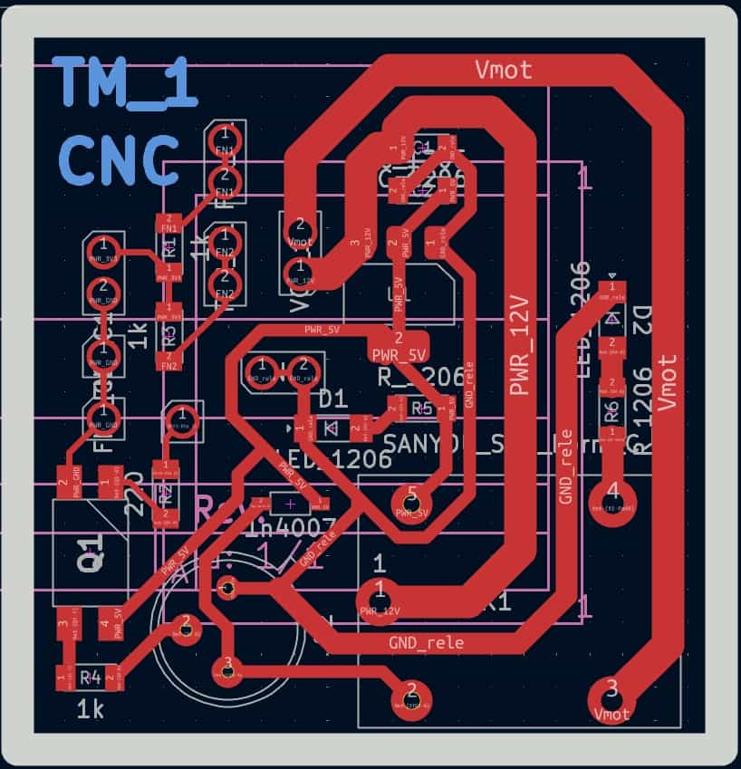
For manufacturing, we used the Monofab. The PCB design involved four layers: one for marking true holes for the pins, transistor, and relay; another for etching the traces; a third for engraving; and the final layer for cutting the board.
The components were manually soldered using a soldering iron and tin.
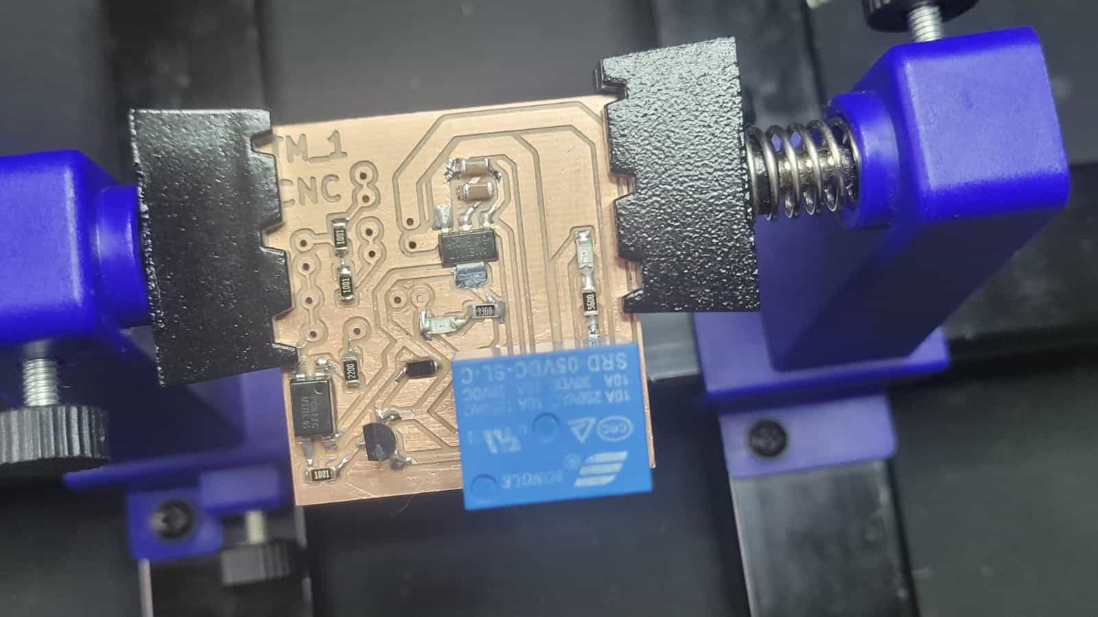
This secondary PCB was designed and manufactured by Erwin and Emmanuel.
7. Programming
The code of the system was developed by Erwin.
7.1 G-code Processing and Step Conversion
This Python script is responsible for converting standard G-code files (typically generated from vector drawings such as SVGs) into a format that our custom firmware can understand. It converts G-code units from millimeters to motor steps, simplifies Z-axis commands into basic up/down signals, and generates both absolute and relative positioning data for CNC control. It also visualizes the drawing path to validate the data before execution.
Key Functionalities:
- Conversion Factor: Calculates steps per millimeter based on pulley diameter and motor steps.
- G-code Parsing: Reads X/Y/Z movement commands and converts them into simplified step-based instructions.
- Relative Positioning: Converts absolute coordinates into incremental movement for microcontrollers.
- Path Plotting: Visualizes the tool path using matplotlib for quick verification.
import matplotlib.pyplot as plt
import re
import math

def calculate_conversion_factor(diameter_external_mm, steps_per_revolution):
    avance_por_giro = math.pi * diameter_external_mm
    conversion_factor = steps_per_revolution / avance_por_giro
    return conversion_factor

def process_gcode(file_path, output_path, conversion_factor):
    x_coords = []
    y_coords = []

    with open(file_path, 'r') as file:
        lines = file.readlines()

    with open(output_path, 'w') as output_file:
        output_file.write("%\n")

        for line in lines:
            match = re.search(r'X(-?\d+(\.\d+)?)\s+Y(-?\d+(\.\d+)?)', line)
            if match:
                x_mm = float(match.group(1))
                y_mm = float(match.group(3))
                x_steps = round(x_mm * conversion_factor)
                y_steps = round(y_mm * conversion_factor)
                x_coords.append(x_steps)
                y_coords.append(y_steps)
                output_file.write(f"X{x_steps} Y{y_steps}\n")

            elif re.match(r'G00 Z', line):
                z_match = re.search(r'G00 Z(-?\d+(\.\d+)?)', line)
                if z_match:
                    z_value = float(z_match.group(1))
                    if z_value > 0:
                        output_file.write("S1\n")
                    elif z_value < 0:
                        output_file.write("S0\n")

            elif re.match(r'G01 Z-', line):
                output_file.write("S0\n")

        output_file.write("%\n")
    return x_coords, y_coords

def generate_relative_gcode(input_path, relative_output_path):
    prev_x = 0
    prev_y = 0

    with open(input_path, 'r') as infile, open(relative_output_path, 'w') as outfile:
        outfile.write("%\n")
        for line in infile:
            match = re.match(r'X(-?\d+)\s+Y(-?\d+)', line)
            if match:
                x = int(match.group(1))
                y = int(match.group(2))
                dx = x - prev_x
                dy = y - prev_y
                outfile.write(f"X{dx} Y{dy}\n")
                prev_x = x
                prev_y = y
            elif line.strip() in ["S1", "S0"]:
                outfile.write(line)
        outfile.write("%\n")

def plot_coordinates(x_coords, y_coords):
    plt.figure(figsize=(6, 6))
    plt.plot(x_coords, y_coords, marker='o', linestyle='-', color='b')
    plt.xlabel('Coordenada X (Pasos)')
    plt.ylabel('Coordenada Y (Pasos)')
    plt.grid(True)
    plt.axis('equal')
    plt.show()

diameter_external_mm = 16
steps_per_revolution = 400

conversion_factor = calculate_conversion_factor(diameter_external_mm, steps_per_revolution)

input_file = 'T1_0008.txt'
absolute_output = 'absolute_gcode_steps.txt'
relative_output = 'relative_gcode_steps.txt'

x_coords, y_coords = process_gcode(input_file, absolute_output, conversion_factor)

generate_relative_gcode(absolute_output, relative_output)

plot_coordinates(x_coords, y_coords)
1. Conversion Factor Calculation
This function calculates how many motor steps are needed to move 1 millimeter, based on the diameter of the pulley and motor step resolution:
def calculate_conversion_factor(diameter_external_mm, steps_per_revolution):
    avance_por_giro = math.pi * diameter_external_mm
    conversion_factor = steps_per_revolution / avance_por_giro
    return conversion_factor
The conversion factor is used to convert real-world distances into motor steps throughout the script.
2. Processing G-code into Absolute Step Commands
This function reads a G-code file, extracts X/Y coordinates and Z-axis commands, converts millimeters into steps, and writes them into a new file. It also simplifies Z-axis lifting/lowering into "S1" (up) and "S0" (down) commands:
def process_gcode(file_path, output_path, conversion_factor):
    x_coords = []
    y_coords = []

    with open(file_path, 'r') as file:
        lines = file.readlines()

    with open(output_path, 'w') as output_file:
        output_file.write("%\n")

        for line in lines:
            match = re.search(r'X(-?\d+(\.\d+)?)\s+Y(-?\d+(\.\d+)?)', line)
            if match:
                x_mm = float(match.group(1))
                y_mm = float(match.group(3))
                x_steps = round(x_mm * conversion_factor)
                y_steps = round(y_mm * conversion_factor)
                x_coords.append(x_steps)
                y_coords.append(y_steps)
                output_file.write(f"X{x_steps} Y{y_steps}\n")

            elif re.match(r'G00 Z', line):
                z_match = re.search(r'G00 Z(-?\d+(\.\d+)?)', line)
                if z_match:
                    z_value = float(z_match.group(1))
                    if z_value > 0:
                        output_file.write("S1\n")
                    elif z_value < 0:
                        output_file.write("S0\n")

            elif re.match(r'G01 Z-', line):
                output_file.write("S0\n")

        output_file.write("%\n")
    return x_coords, y_coords
3. Creating Relative G-code
This function takes the absolute step values and converts them into relative positions — better suited for microcontroller-based interpreters:
def generate_relative_gcode(input_path, relative_output_path):
    prev_x = 0
    prev_y = 0

    with open(input_path, 'r') as infile, open(relative_output_path, 'w') as outfile:
        outfile.write("%\n")
        for line in infile:
            match = re.match(r'X(-?\d+)\s+Y(-?\d+)', line)
            if match:
                x = int(match.group(1))
                y = int(match.group(2))
                dx = x - prev_x
                dy = y - prev_y
                outfile.write(f"X{dx} Y{dy}\n")
                prev_x = x
                prev_y = y
            elif line.strip() in ["S1", "S0"]:
                outfile.write(line)
        outfile.write("%\n")
4. Plotting the Motion Path
This visualization function plots the final X/Y steps as a connected line drawing — making it easy to preview the result of the processed G-code before using it:
def plot_coordinates(x_coords, y_coords):
    plt.figure(figsize=(6, 6))
    plt.plot(x_coords, y_coords, marker='o', linestyle='-', color='b')
    plt.xlabel('Coordenada X (Pasos)')
    plt.ylabel('Coordenada Y (Pasos)')
    plt.grid(True)
    plt.axis('equal')
    plt.show()
5. Full Workflow Execution
This is the portion that initializes the script, sets the machine parameters, and runs the full process:
diameter_external_mm = 16
steps_per_revolution = 400

conversion_factor = calculate_conversion_factor(diameter_external_mm, steps_per_revolution)

input_file = 'T1_0008.txt'
absolute_output = 'absolute_gcode_steps.txt'
relative_output = 'relative_gcode_steps.txt'

x_coords, y_coords = process_gcode(input_file, absolute_output, conversion_factor)
generate_relative_gcode(absolute_output, relative_output)
plot_coordinates(x_coords, y_coords)
With this script, we successfully convert millimeter-based G-code into a minimal step-and-command format ready to be interpreted by our microcontroller-based CNC firmware.
7.2 Serial Communication with the Microcontroller
This script is responsible for establishing a serial connection between the computer and the XIAO ESP32 (or similar microcontroller), then sending each line of G-code step data to it one at a time. The microcontroller is expected to respond with an ok after each line, confirming that the command was received and executed.
import serial
import time

PORT = 'COM13'
BAUD_RATE = 115200
TXT_FILE = 'absolute_gcode_steps.txt'

time.sleep(2)

try:
    ser = serial.Serial(PORT, BAUD_RATE, timeout=2)
    print(f"Conectado a {PORT} a {BAUD_RATE} baudios")
except serial.SerialException:
    print(f"Error al conectar al puerto {PORT}")
    exit()

with open(TXT_FILE, 'r') as file:
    for line in file:
        line = line.strip()
        if not line:
            continue

        print(f"Enviando: {line}")
        ser.write((line + '\n').encode())

        response = ""
        while True:
            if ser.in_waiting > 0:
                response += ser.read(ser.in_waiting).decode()
                if 'ok' in response.lower():
                    print("Recibido: ok\n")
                    break

ser.close()
print("Envio de instrucciones finalizado.")
1. Establishing Serial Communication
PORT = 'COM13'
BAUD_RATE = 115200
TXT_FILE = 'absolute_gcode_steps.txt'

time.sleep(2)
These lines define the serial communication settings. It sets:
- PORT to COM13 (change this to match your device's port)
- BAUD_RATE to 115200 (must match the microcontroller)
- TXT_FILE to the path of the G-code steps file created earlier
2. Opening the Serial Port
try:
    ser = serial.Serial(PORT, BAUD_RATE, timeout=2)
    print(f"Conectado a {PORT} a {BAUD_RATE} baudios")
except serial.SerialException:
    print(f"Error al conectar al puerto {PORT}")
    exit()
This block attempts to connect to the serial port. If it fails, the program exits gracefully with an error message. If successful, it confirms the connection in the console.
3. Sending Each Line to the Microcontroller
with open(TXT_FILE, 'r') as file:
    for line in file:
        line = line.strip()
        if not line:
            continue
The script opens the G-code steps file and processes each line. Empty lines are ignored.
4. Writing and Waiting for Acknowledgement
        print(f"Enviando: {line}")
        ser.write((line + '\n').encode())

        response = ""
        while True:
            if ser.in_waiting > 0:
                response += ser.read(ser.in_waiting).decode()
                if 'ok' in response.lower():
                    print("Recibido: ok\n")
                    break
Each line is sent over the serial connection. The script waits for the microcontroller to respond with "ok" before continuing to the next line. This ensures synchronized, step-by-step execution of G-code instructions.
5. Closing the Serial Connection
ser.close()
print("Envio de instrucciones finalizado.")
After all commands are sent, the script closes the serial port cleanly and prints a confirmation message.
7.3 Arduino Firmware for XIAO Microcontroller
This code runs on the XIAO and interprets custom G-code-style commands received over serial to move stepper motors via AccelStepper and control a servo for pen-up/pen-down actions. It includes homing logic using endstop switches, motion buffering, and speed-proportional multi-axis movement.
#include <AccelStepper.h>
#include <Servo.h>

#if defined(ESP32)
  #define ISR_ATTR IRAM_ATTR
#else
  #define ISR_ATTR
#endif

// ==== Pines ====
#define X_STEP_PIN D6
#define X_DIR_PIN  D7
#define Y_STEP_PIN D8
#define Y_DIR_PIN  D9
#define SERVO_PIN  D10
#define ENABLE_PIN D0
#define ENDSTOP_X_PIN D2
#define ENDSTOP_Y_PIN D3

AccelStepper stepperX(AccelStepper::DRIVER, X_STEP_PIN, X_DIR_PIN);
AccelStepper stepperY(AccelStepper::DRIVER, Y_STEP_PIN, Y_DIR_PIN);
Servo zServo;

// ==== Variables ====
long currentX = 0;
long currentY = 0;

const int BUFFER_SIZE = 20;
long bufferX[BUFFER_SIZE];
long bufferY[BUFFER_SIZE];
int bufferCount = 0;

const float speed = 350;
float homingSpeed = 100;
int homingDirX = 1;
int homingDirY = 1;
int retractSteps = 1750;

// ==== Estados ====
bool isExecuting = false;
bool waitingServo = false;
bool servoUp = true;
bool motorsEnabled = false;
bool homingDone = false;

String serialLine = "";

// ==== Finales de carrera ====
volatile bool endstopX_triggered = false;
volatile bool endstopY_triggered = false;

void ISR_ATTR endstopX_ISR() {
  endstopX_triggered = true;
}

void ISR_ATTR endstopY_ISR() {
  endstopY_triggered = true;
}

// ==== Funciones ====
void enableMotors(bool state) {
  digitalWrite(ENABLE_PIN, state ? HIGH : LOW);
}

void homeAxis(AccelStepper& stepper, int endstopPin, volatile bool& endstopFlag, int dir) {
  zServo.write(180);
  delay(300);
  stepper.setMaxSpeed(homingSpeed);
  stepper.setSpeed(homingSpeed * -dir);
  while (!endstopFlag) {
    stepper.runSpeed();
  }
  stepper.stop();
  delay(500);
  stepper.setCurrentPosition(0);
  stepper.setSpeed(dir * homingSpeed);
  for (int i = 0; i < retractSteps; i++) {
    stepper.runSpeed();
    delay(2);
  }
  delay(500);
  endstopFlag = false;
}

void processMove(long targetX, long targetY) {
  long deltaX = targetX - currentX;
  long deltaY = targetY - currentY;

  long distance = sqrt(deltaX * deltaX + deltaY * deltaY);
  if (distance == 0) return;

  float proportionX = abs(deltaX) / (float)distance;
  float proportionY = abs(deltaY) / (float)distance;

  stepperX.setSpeed(speed * (deltaX > 0 ? 1 : -1) * proportionX);
  stepperY.setSpeed(speed * (deltaY > 0 ? 1 : -1) * proportionY);

  long stepsX = abs(deltaX);
  long stepsY = abs(deltaY);
  long stepsDoneX = 0;
  long stepsDoneY = 0;

  while (stepsDoneX < stepsX || stepsDoneY < stepsY) {
    if (stepsDoneX < stepsX && stepperX.runSpeed()) stepsDoneX++;
    if (stepsDoneY < stepsY && stepperY.runSpeed()) stepsDoneY++;
  }

  currentX = targetX;
  currentY = targetY;
}

void processServo(bool up) {
  if (up && !servoUp) {
    zServo.write(180);
    delay(300);
    servoUp = true;
  } else if (!up && servoUp) {
    zServo.write(0);
    delay(300);
    servoUp = false;
  }
}

void setup() {
  Serial.begin(115200);

  pinMode(ENABLE_PIN, OUTPUT);
  enableMotors(false);

  pinMode(ENDSTOP_X_PIN, INPUT);
  pinMode(ENDSTOP_Y_PIN, INPUT);
  attachInterrupt(digitalPinToInterrupt(ENDSTOP_X_PIN), endstopX_ISR, FALLING);
  attachInterrupt(digitalPinToInterrupt(ENDSTOP_Y_PIN), endstopY_ISR, FALLING);

  stepperX.setMaxSpeed(speed);
  stepperY.setMaxSpeed(speed);
  stepperX.setSpeed(0);
  stepperY.setSpeed(0);

  zServo.attach(SERVO_PIN);
  zServo.write(0);
}

void loop() {
 enableMotors(true);
  while (Serial.available()) {
    char c = Serial.read();
    if (c == '\n') {
      serialLine.trim();

      if (serialLine.startsWith("%")) {
        homeAxis(stepperX, ENDSTOP_X_PIN, endstopX_triggered, homingDirX);
        homeAxis(stepperY, ENDSTOP_Y_PIN, endstopY_triggered, homingDirY);
        stepperX.setMaxSpeed(speed);
        stepperY.setMaxSpeed(speed);
        currentX = 0;
        currentY = 0;
        Serial.println("ok");
      }

      if (serialLine.startsWith("S")) {
        for (int i = 0; i < bufferCount; i++) {
          processMove(bufferX[i], bufferY[i]);
        }
        bufferCount = 0;

        processServo(serialLine == "S1");
        Serial.println("ok");

      } else if (serialLine.startsWith("X")) {
        int xIndex = serialLine.indexOf('X');
        int yIndex = serialLine.indexOf('Y');
        if (xIndex >= 0 && yIndex > xIndex) {
          long xVal = serialLine.substring(xIndex + 1, yIndex-1).toInt();
          long yVal = serialLine.substring(yIndex + 1).toInt();

          if (bufferCount < BUFFER_SIZE) {
            bufferX[bufferCount] = xVal;
            bufferY[bufferCount] = yVal;
            bufferCount++;
            Serial.println("ok");
          } else {
            processMove(bufferX[0], bufferY[0]);
            for (int i = 1; i < bufferCount; i++) {
              bufferX[i - 1] = bufferX[i];
              bufferY[i - 1] = bufferY[i];
            }
            bufferCount--;
            Serial.println("ok");
          }
        }
      }

      serialLine = "";
    } else {
      serialLine += c;
    }
  }
}
1. Library Inclusions and Configuration
#include <AccelStepper.h>
#include <Servo.h>
These libraries allow the microcontroller to control stepper motors with acceleration support (AccelStepper) and servo motors (Servo). The conditional definition of ISR_ATTR ensures compatibility with ESP32’s interrupt handling.
2. Pin Definitions and Stepper Initialization
#define X_STEP_PIN D6
#define X_DIR_PIN  D7
...
AccelStepper stepperX(AccelStepper::DRIVER, X_STEP_PIN, X_DIR_PIN);
Each axis is controlled using step/direction pins. A Servo is defined for Z-axis control. The ENABLE_PIN toggles power to the stepper drivers, and ENDSTOP_X/Y are digital limit switches.
3. Motion and Control Variables
long currentX = 0;
long bufferX[BUFFER_SIZE];
float speed = 350;
bool homingDone = false;
Coordinates and buffer arrays store incoming movement instructions. Speed values and flags like servoUp manage motion states and direction.
4. Endstop Interrupt Handlers
void ISR_ATTR endstopX_ISR() {
  endstopX_triggered = true;
}
These functions are triggered when an endstop switch is pressed, allowing precise homing to axis zero points.
5. Enabling or Disabling Stepper Power
void enableMotors(bool state) {
  digitalWrite(ENABLE_PIN, state ? HIGH : LOW);
}
This helper function toggles the motor driver's sleep or enable pin.
6. Homing Routine
void homeAxis(...) {
  ...
  while (!endstopFlag) {
    stepper.runSpeed();
  }
  ...
}
Moves the motor in a set direction until an endstop switch is triggered, then slightly retracts to zero the axis and avoid mechanical pressure.
7. Movement Execution (processMove)
void processMove(long targetX, long targetY) {
  ...
  while (stepsDoneX < stepsX || stepsDoneY < stepsY) {
    if (...) stepperX.runSpeed();
    if (...) stepperY.runSpeed();
  }
}
Moves both axes using a proportion-based system that keeps the X and Y motions synchronized along a linear path.
8. Servo Control
void processServo(bool up) {
  zServo.write(up ? 180 : 0);
}
Raises or lowers the pen/tool by rotating the servo to a predefined angle.
9. setup()
void setup() {
  ...
  attachInterrupt(...);
  zServo.attach(SERVO_PIN);
}
Initializes serial, configures pins, enables interrupts, and sets up motor speed limits.
10. Main loop()
while (Serial.available()) {
  ...
  if (serialLine.startsWith("%")) homeAxis(...);
  if (serialLine.startsWith("S")) processServo(...);
  if (serialLine.startsWith("X")) bufferX[...] = ...;
}
Reads each serial command line by line. It:
- Homes both axes on receiving
%. - Triggers pen up/down on
S1orS0. - Buffers X/Y step values and flushes when full.
9. Future Improvements
Although our CNC plotter performs its intended function reliably, there are several opportunities to enhance its performance, durability, and user experience in future iterations. Some proposed improvements include:
- 1. Development of a Custom PC Interface: Creating a desktop application or web-based interface would greatly improve usability. It could allow users to upload G-code files, visualize the toolpath, and send instructions to the machine wirelessly.
- 2. Main PCB Design Refinement: The current board suffered damage due to simultaneous USB and external power connections. A revised design with power selection jumpers or automatic switching circuitry would prevent overvoltage issues and protect the microcontroller.
- 3. Improved Z-Axis Precision: Replacing the rack-and-pinion Z-axis with a threaded lead screw or linear actuator could reduce backlash and improve vertical resolution, enabling finer detail in plots.
- 4. Enclosure or Protective Casing: Designing a full enclosure for the electronics and possibly the entire machine would protect the system from dust, debris, and accidental physical damage.
- 5. Improved Cable Management: Organizing wires into neatly routed cable chains or braided sleeves would enhance safety, maintenance, and aesthetics.
- 6. Wireless Communication Upgrade: Although serial USB worked reliably, adding support for Wi-Fi or Bluetooth control using a XIAO ESP32 would further untether the machine and modernize the workflow.
- 7. Pen Pressure Control: For more advanced plotting, implementing a pressure-sensitive or spring-loaded pen holder could help maintain consistent line thickness, especially on uneven surfaces.