FAST TRACER – My contributions
The primary objective of this project was to develop a CNC machine capable of creating drawings with both speed and precision. From the start, I focused on designing a stable mechanical structure that ensured reliable movement of the drawing head. I prioritized robust construction over expanding the machine's features, favoring quality and mechanical performance to achieve accurate results.
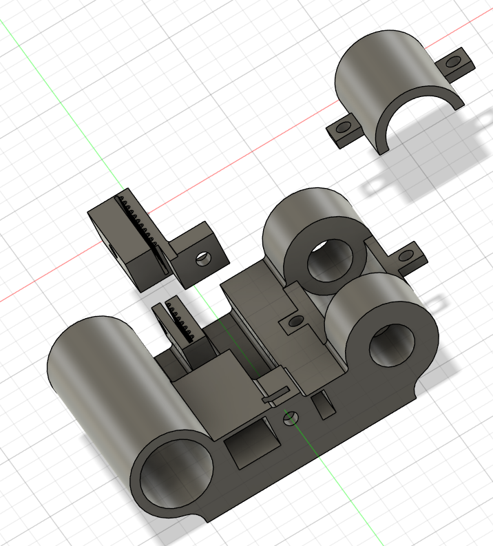
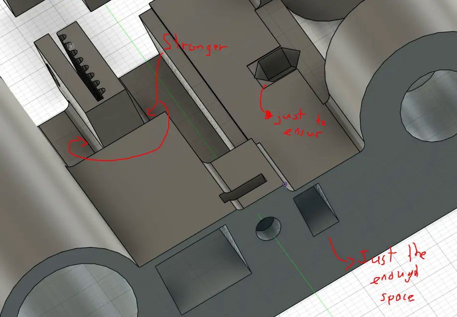
Design of the axle carriage
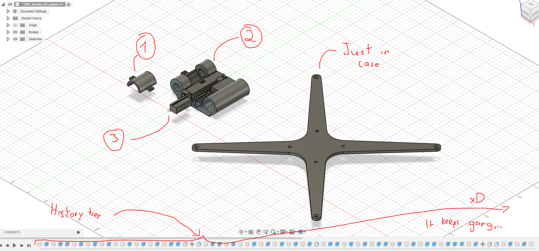
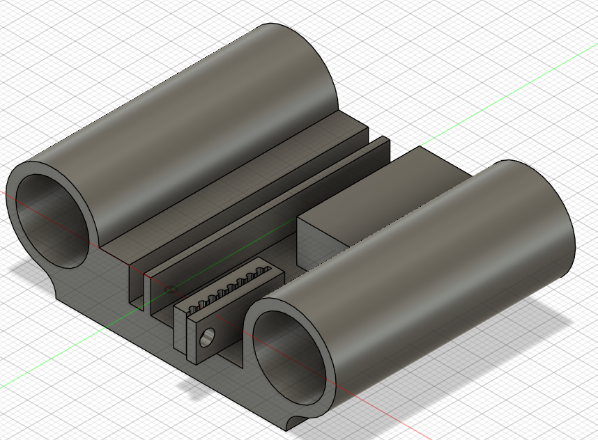
Much of my effort was directed toward designing the carriage system for the X and Y axes. To facilitate iteration and optimization, I made extensive use of Fusion 360's version history. This allowed me to revert changes easily and experiment without fear of losing previous progress. Throughout the process, I made several key improvements:
- Adjusted the spacing for the timing belts to achieve optimal tension.
- Applied precise tolerance to the linear bearing slots, ensuring they fit tightly without excessive force.
- Included a removable cover to simplify maintenance and access to the bearings.
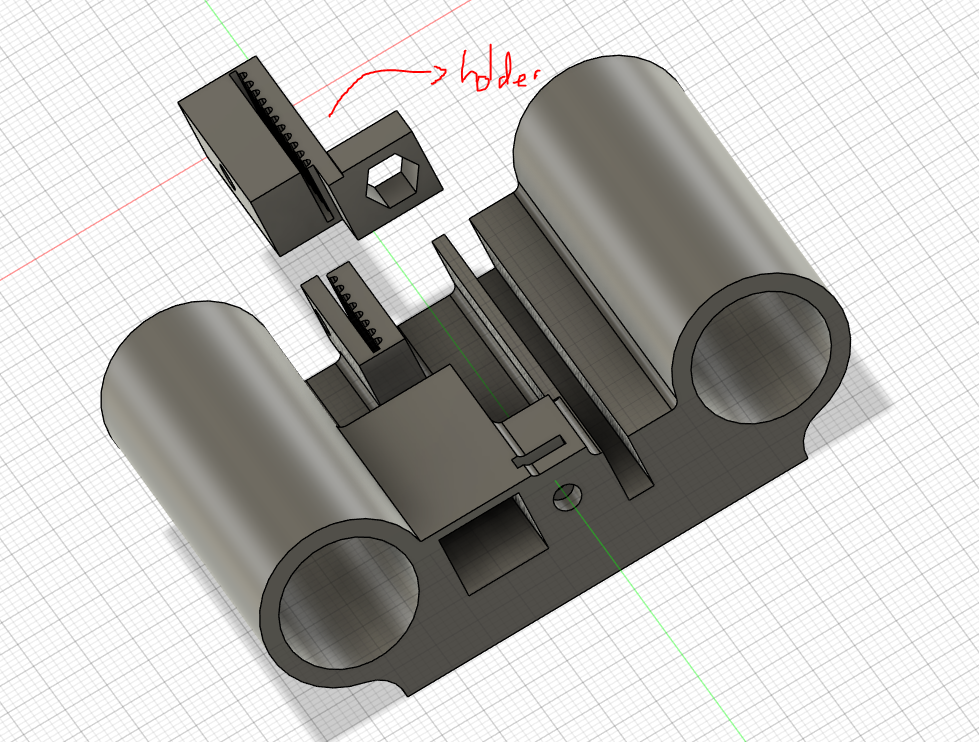
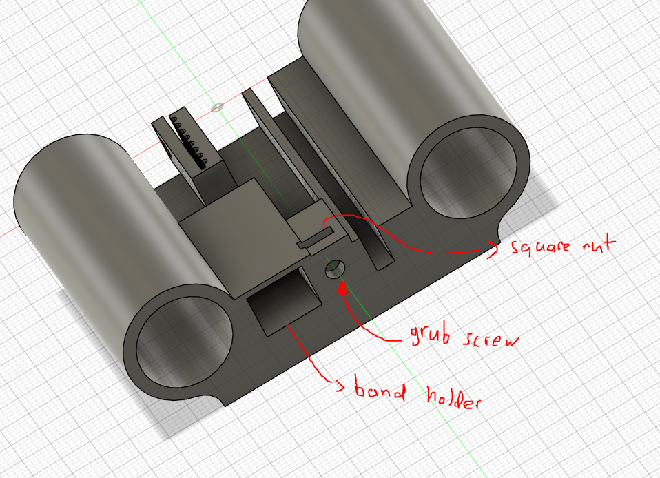
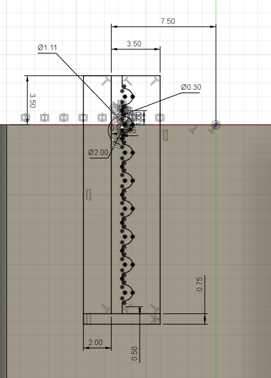
- Designed belt tensioners inspired by the Prusa MK4’s Y-axis system, using screws and embedded nuts.
- Incorporated a press-fit, toothed belt anchor system that holds the belts firmly in place.
- Carefully aligned the shaft holders to keep the rods level and reduce friction due to misalignment.

Just in case PCB
To prevent damage to the microcontroller in the event of an improper power-up sequence, I designed and fabricated a custom safety circuit on a PCB. This circuit manages the power delivery to the stepper motors, ensuring they are energized only after the controller is fully initialized. This is fully described in the CNC page. Still...
In summarize, the circuit uses an optocoupler to electrically isolate the control signal from the power section. When the microcontroller outputs a HIGH signal on the designated control pin, the optocoupler activates a 2N2222 NPN transistor. This, in turn, energizes a relay coil, allowing current to flow to the stepper motor drivers. A flyback diode protects the transistor from voltage spikes generated when the relay turns off. Additionally, an AMS1117 voltage regulator provides a safe 5V supply to the relay, stepping down from the main 12V input. Also, pull-up resistors were added to support mechanical endstops, we had the time to add them at the final day. They ensure accurate detection without using pre-built modules.
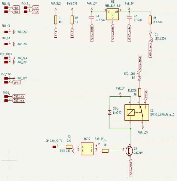
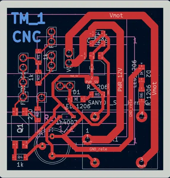
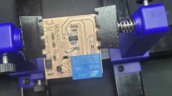
Figure 11: Main welded components.
And finally, my biggest intervention…
The CODE
Inkscape g code extension video.
Our Inkscape g code generation example:
I chose to write the firmware entirely from scratch in C++, using the Arduino IDE. Rather than rely on external CNC platforms, I implemented core functionalities myself. I included only the AccelStepper library to simplify stepper control. Initially, I tested motion with acceleration enabled, but found it introduced small pauses during short moves. Because the mechanics performed so well, I opted for constant speed to improve responsiveness. I also implemented a buffered command system, allowing the microcontroller to queue up to ten movement instructions. This reduced interruptions and helped maintain smooth transitions during drawing. To maintain sync with the PC, the system uses an ACK-based protocol: each instruction is acknowledged before accepting the next. For motion interpolation, I used Pythagoras' theorem to calculate the appropriate step ratio between motors, so they arrive at target coordinates simultaneously. This technique proved effective for simulating curves when using the “approximation of curves to straight lines” function of Inkscape.
Finally, I developed 2 Python scripts to adapt/simplify and visualize G-code paths before sending them to the machine. This allowed me to verify drawing accuracy ahead of time.
  import matplotlib.pyplot as plt
  import re
  import math

  def calculate_conversion_factor(diameter_external_mm, steps_per_revolution):
      avance_por_giro = math.pi * diameter_external_mm
      conversion_factor = steps_per_revolution / avance_por_giro
      return conversion_factor

  def process_gcode(file_path, output_path, conversion_factor):
      x_coords = []
      y_coords = []

      with open(file_path, 'r') as file:
          lines = file.readlines()

      with open(output_path, 'w') as output_file:
          output_file.write("%\n")

          for line in lines:
              match = re.search(r'X(-?\d+(\.\d+)?)\s+Y(-?\d+(\.\d+)?)', line)
              if match:
                  x_mm = float(match.group(1))
                  y_mm = float(match.group(3))
                  x_steps = round(x_mm * conversion_factor)
                  y_steps = round(y_mm * conversion_factor)
                  x_coords.append(x_steps)
                  y_coords.append(y_steps)
                  output_file.write(f"X{x_steps} Y{y_steps}\n")

              elif re.match(r'G00 Z', line):
                  z_match = re.search(r'G00 Z(-?\d+(\.\d+)?)', line)
                  if z_match:
                      z_value = float(z_match.group(1))
                      if z_value > 0:
                          output_file.write("S1\n")
                      elif z_value < 0:
                          output_file.write("S0\n")

              elif re.match(r'G01 Z-', line):
                  output_file.write("S0\n")

          output_file.write("%\n")
      return x_coords, y_coords

  def generate_relative_gcode(input_path, relative_output_path):
      prev_x = 0
      prev_y = 0

      with open(input_path, 'r') as infile, open(relative_output_path, 'w') as outfile:
          outfile.write("%\n")
          for line in infile:
              match = re.match(r'X(-?\d+)\s+Y(-?\d+)', line)
              if match:
                  x = int(match.group(1))
                  y = int(match.group(2))
                  dx = x - prev_x
                  dy = y - prev_y
                  outfile.write(f"X{dx} Y{dy}\n")
                  prev_x = x
                  prev_y = y
              elif line.strip() in ["S1", "S0"]:
                  outfile.write(line)
          outfile.write("%\n")

  def plot_coordinates(x_coords, y_coords):
      plt.figure(figsize=(6, 6))
      plt.plot(x_coords, y_coords, marker='o', linestyle='-', color='b')
      plt.xlabel('Coordenada X (Pasos)')
      plt.ylabel('Coordenada Y (Pasos)')
      plt.grid(True)
      plt.axis('equal')
      plt.show()

  diameter_external_mm = 16
  steps_per_revolution = 400

  conversion_factor = calculate_conversion_factor(diameter_external_mm, steps_per_revolution)

  input_file = 'T1_0008.txt'
  absolute_output = 'absolute_gcode_steps.txt'
  relative_output = 'relative_gcode_steps.txt'

  x_coords, y_coords = process_gcode(input_file, absolute_output, conversion_factor)

  generate_relative_gcode(absolute_output, relative_output)

  plot_coordinates(x_coords, y_coords)
This Python script automates the transformation of G-code coordinates from millimeters to motor steps, and subsequently generates both absolute and relative step coordinates for use in CNC or plotting systems. The script also includes a plotting function to visualize the toolpath. Below is a breakdown of each part of the script.
The function `calculate_conversion_factor(diameter_external_mm, steps_per_revolution)` computes a conversion factor by dividing the number of steps per revolution of a stepper motor by the linear distance covered in one rotation, calculated as π times the pulley or wheel diameter. This allows conversion from millimeters to motor steps.
The `process_gcode(file_path, output_path, conversion_factor)` function reads a G-code file and extracts X and Y coordinates using a regular expression. These coordinates are then multiplied by the conversion factor to obtain equivalent motor steps. It also interprets Z-axis motion commands, converting them into simplified 'S1' and 'S0' commands for tool activation or deactivation. The processed output is saved into a new file.
The function `generate_relative_gcode(input_path, relative_output_path)` creates a relative movement version of the previously generated absolute coordinates. It calculates the difference between consecutive X and Y steps and writes these deltas to a new file. This relative approach is especially useful in step-by-step CNC control or systems that process incremental motion.
The `plot_coordinates(x_coords, y_coords)` function uses matplotlib to render a visual representation of the path followed by the machine. It ensures the plot maintains aspect ratio and grid alignment for clarity, plotting each point in order with a line connecting them.
In the execution section, the pulley diameter and motor step resolution are defined. The G-code file `T1_0008.txt` is processed into an absolute step-based file, then converted into a relative file. Finally, the coordinates are plotted.
  import serial
  import time

  PORT = 'COM13'
  BAUD_RATE = 115200
  TXT_FILE = 'absolute_gcode_steps.txt'

  time.sleep(2)

  try:
      ser = serial.Serial(PORT, BAUD_RATE, timeout=2)
      print(f"Conectado a {PORT} a {BAUD_RATE} baudios")
  except serial.SerialException:
      print(f"Error al conectar al puerto {PORT}")
      exit()

  with open(TXT_FILE, 'r') as file:
      for line in file:
          line = line.strip()
          if not line:
              continue

          print(f"Enviando: {line}")
          ser.write((line + '\n').encode())

          response = ""
          while True:
              if ser.in_waiting > 0:
                  response += ser.read(ser.in_waiting).decode()
                  if 'ok' in response.lower():
                      print("Recibido: ok\n")
                      break

  ser.close()
  print("Envio de instrucciones finalizado.")
This script is designed to establish a serial connection between a computer and a microcontroller (such as an ESP32 or RP2040) to send G-code instructions stored in a text file. The primary goal is to sequentially send each line of the file through the serial port and wait for confirmation ('ok') from the device before proceeding to the next command. This approach ensures synchronization and safe execution of motion or actuation instructions on the receiving end.
The script begins by defining the serial port (`COM13`), baud rate (`115200`), and the name of the G-code file to be read. It waits for 2 seconds using `time.sleep(2)` to allow the microcontroller to boot up and be ready to receive commands. Then it attempts to establish a serial connection using `serial.Serial`. If the connection fails, the program prints an error message and exits gracefully.
Once connected, the script opens the specified G-code file and reads it line by line. Empty lines are skipped to avoid unnecessary transmissions. Each valid line is trimmed and printed to the console before being sent over the serial connection, appended with a newline character and encoded to bytes.
After sending each command, the script enters a loop to listen for a response from the microcontroller. It waits until the device sends a string containing 'ok', indicating that the command was received and executed. Once this confirmation is received, the script breaks out of the loop and proceeds to the next line. This handshake mechanism prevents command overlap or data loss.
At the end of the transmission, the serial port is closed, and a completion message is printed.
  #include AccelStepper.h
  #include Servo.h

  #if defined(ESP32)
    #define ISR_ATTR IRAM_ATTR
  #else
    #define ISR_ATTR
  #endif

  // ==== Pines ====
  #define X_STEP_PIN D6
  #define X_DIR_PIN  D7
  #define Y_STEP_PIN D8
  #define Y_DIR_PIN  D9
  #define SERVO_PIN  D10
  #define ENABLE_PIN D0
  #define ENDSTOP_X_PIN D2
  #define ENDSTOP_Y_PIN D3

  AccelStepper stepperX(AccelStepper::DRIVER, X_STEP_PIN, X_DIR_PIN);
  AccelStepper stepperY(AccelStepper::DRIVER, Y_STEP_PIN, Y_DIR_PIN);
  Servo zServo;

  // ==== Variables ====
  long currentX = 0;
  long currentY = 0;

  const int BUFFER_SIZE = 20;
  long bufferX[BUFFER_SIZE];
  long bufferY[BUFFER_SIZE];
  int bufferCount = 0;

  const float speed = 350;
  float homingSpeed = 100;
  int homingDirX = 1;
  int homingDirY = 1;
  int retractSteps = 1750;

  // ==== Estados ====
  bool isExecuting = false;
  bool waitingServo = false;
  bool servoUp = true;
  bool motorsEnabled = false;
  bool homingDone = false;

  String serialLine = "";

  // ==== Finales de carrera ====
  volatile bool endstopX_triggered = false;
  volatile bool endstopY_triggered = false;

  void ISR_ATTR endstopX_ISR() {
    endstopX_triggered = true;
  }

  void ISR_ATTR endstopY_ISR() {
    endstopY_triggered = true;
  }

  // ==== Funciones ====
  void enableMotors(bool state) {
    digitalWrite(ENABLE_PIN, state ? HIGH : LOW);
  }

  void homeAxis(AccelStepper& stepper, int endstopPin, volatile bool& endstopFlag, int dir) {
    zServo.write(180);
    delay(300);
    stepper.setMaxSpeed(homingSpeed);
    stepper.setSpeed(homingSpeed * -dir);
    while (!endstopFlag) {
      stepper.runSpeed();
    }
    stepper.stop();
    delay(500);
    stepper.setCurrentPosition(0);
    stepper.setSpeed(dir * homingSpeed);
    for (int i = 0; i < retractSteps; i++) {
      stepper.runSpeed();
      delay(2);
    }
    delay(500);
    endstopFlag = false;
  }

  void processMove(long targetX, long targetY) {
    long deltaX = targetX - currentX;
    long deltaY = targetY - currentY;

    long distance = sqrt(deltaX * deltaX + deltaY * deltaY);
    if (distance == 0) return;

    float proportionX = abs(deltaX) / (float)distance;
    float proportionY = abs(deltaY) / (float)distance;

    stepperX.setSpeed(speed * (deltaX > 0 ? 1 : -1) * proportionX);
    stepperY.setSpeed(speed * (deltaY > 0 ? 1 : -1) * proportionY);

    long stepsX = abs(deltaX);
    long stepsY = abs(deltaY);
    long stepsDoneX = 0;
    long stepsDoneY = 0;

    while (stepsDoneX < stepsX || stepsDoneY < stepsY) {
      if (stepsDoneX < stepsX && stepperX.runSpeed()) stepsDoneX++;
      if (stepsDoneY < stepsY && stepperY.runSpeed()) stepsDoneY++;
    }

    currentX = targetX;
    currentY = targetY;
  }

  void processServo(bool up) {
    if (up && !servoUp) {
      zServo.write(180);
      delay(300);
      servoUp = true;
    } else if (!up && servoUp) {
      zServo.write(0);
      delay(300);
      servoUp = false;
    }
  }

  void setup() {
    Serial.begin(115200);

    pinMode(ENABLE_PIN, OUTPUT);
    enableMotors(false);

    pinMode(ENDSTOP_X_PIN, INPUT);
    pinMode(ENDSTOP_Y_PIN, INPUT);
    attachInterrupt(digitalPinToInterrupt(ENDSTOP_X_PIN), endstopX_ISR, FALLING);
    attachInterrupt(digitalPinToInterrupt(ENDSTOP_Y_PIN), endstopY_ISR, FALLING);

    stepperX.setMaxSpeed(speed);
    stepperY.setMaxSpeed(speed);
    stepperX.setSpeed(0);
    stepperY.setSpeed(0);

    zServo.attach(SERVO_PIN);
    zServo.write(0);
  }

  void loop() {
   enableMotors(true);
    while (Serial.available()) {
      char c = Serial.read();
      if (c == '\n') {
        serialLine.trim();

        if (serialLine.startsWith("%")) {
          homeAxis(stepperX, ENDSTOP_X_PIN, endstopX_triggered, homingDirX);
          homeAxis(stepperY, ENDSTOP_Y_PIN, endstopY_triggered, homingDirY);
          stepperX.setMaxSpeed(speed);
          stepperY.setMaxSpeed(speed);
          currentX = 0;
          currentY = 0;
          Serial.println("ok");
        }

        if (serialLine.startsWith("S")) {
          for (int i = 0; i < bufferCount; i++) {
            processMove(bufferX[i], bufferY[i]);
          }
          bufferCount = 0;

          processServo(serialLine == "S1");
          Serial.println("ok");

        } else if (serialLine.startsWith("X")) {
          int xIndex = serialLine.indexOf('X');
          int yIndex = serialLine.indexOf('Y');
          if (xIndex >= 0 && yIndex > xIndex) {
            long xVal = serialLine.substring(xIndex + 1, yIndex-1).toInt();
            long yVal = serialLine.substring(yIndex + 1).toInt();

            if (bufferCount < BUFFER_SIZE) {
              bufferX[bufferCount] = xVal;
              bufferY[bufferCount] = yVal;
              bufferCount++;
              Serial.println("ok");
            } else {
              processMove(bufferX[0], bufferY[0]);
              for (int i = 1; i < bufferCount; i++) {
                bufferX[i - 1] = bufferX[i];
                bufferY[i - 1] = bufferY[i];
              }
              bufferCount--;
              Serial.println("ok");
            }
          }
        }

        serialLine = "";
      } else {
        serialLine += c;
      }
    }
  }
This Arduino sketch implements a basic CNC motion controller using two stepper motors (for X and Y axes) and a continuous rotation servo motor (for the Z axis). It interprets commands received over Serial and executes buffered movements along with basic homing functionality using endstop switches.
Libraries and Definitions
The code uses the AccelStepper library to control stepper motors and the Servo library for controlling the Z-axis servo. Conditional macros define the interrupt attribute for compatibility with ESP32. Pins for step, direction, enable, servo, and endstops are defined using macros for clarity and portability.
Motor and Servo Setup
The stepper motors for X and Y axes are initialized using AccelStepper in DRIVER mode. The servo motor is controlled using the Servo class. Homing speed and direction for each axis are configured, along with a retract distance after endstop activation.
Endstop Handling
Two external interrupts are used to detect when the endstop switches are triggered. Flags (`endstopX_triggered`, `endstopY_triggered`) are set to true in their respective interrupt service routines. These flags are used during the homing routine to determine when the axis has reached the home position.
Homing Logic
The function `homeAxis()` performs the homing sequence for a given axis by moving it at a fixed speed in the direction of the endstop until it is triggered. It then retracts by a fixed number of steps to relieve mechanical stress and resets the current position to zero.
Motion Processing
`processMove()` receives a target position (in steps) and calculates the distance from the current position. It computes the relative speed proportionally for both axes to ensure diagonal movements remain accurate. Both motors run simultaneously using `runSpeed()` until the movement is complete.
Servo Control
`processServo()` handles toggling the Z-axis servo up or down. The up position is represented by 180° and the down position by 0°, with a delay included to allow movement to complete.
Serial Communication and Command Buffer
The `loop()` continuously reads from the serial buffer, accumulating characters until a newline is detected. It handles three types of commands:
%: Triggers the homing routine for both axes.S0/S1: Triggers servo movement after executing all buffered motion commands.X... Y...: Buffers the X and Y target positions for later execution.
If the buffer exceeds the predefined capacity, the oldest command is executed and removed from the buffer to maintain flow. After each recognized command, it prints `ok` to acknowledge successful parsing and execution.