12. Mechanical Design, Machine Design
This week, I worked on was making a PCB.
Group Task:
Group taskList of components:
| Quantity | Component | Value / Model | Description |
|---|---|---|---|
| 1 | Microcontroller | XIAO RP2040 | Main microcontroller |
| 2 | Motor driver | A4988 | Stepper motor driver |
| 1 | Voltage regulator | L7805 | 5V voltage converter |
| 2 | Electrolytic capacitor | 100 µF | Power filtering |
| 1 | Electrolytic capacitor | 10 µF | Regulator input capacitor |
| 1 | Electrolytic capacitor | 22 µF | Regulator output capacitor |
| 2 | Resistor | 1 kΩ | Pull-down for endstops |
| 3 | Connector | Header | Motor outputs |
| 1 | Connector | Header | Buzzer |
| 2 | Connector | Header | Endstop inputs |
| 1 | Connector | Header | Z-axis servo |
| 2 | Connector | Header | Endstops 1 and 2 |
| 1 | Connector | Header | OLED display |
| 1 | Connector | Header | Extra pin |
| 1 | Connector | Header | Common GND |
schematic
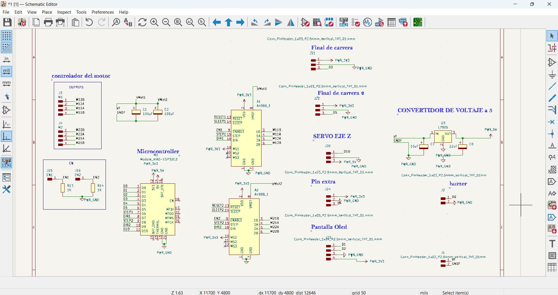
- First, I made the schematic.
Explanation of the CNC Drawing Machine PCB and Its Components
This PCB is designed as the central control unit for a CNC drawing machine. It manages the movement of motors, sensors, and other peripherals through a microcontroller.
What the PCB Does
The PCB controls:
- Two stepper motors that move the X and Y axes.
- A servo motor to control the Z axis (for example, to raise or lower a drawing tool).
- Limit switches (endstops) that detect the physical limits of the machine's movement.
- A voltage regulator to provide stable 5V power.
- All components are managed by an XiaoRP2040 microcontroller.
Note on OLED Display and Buzzer
In this version of the PCB, the OLED display and buzzer have been removed. This decision was made to simplify the design and focus on the core mechanical controls. The removal of these components reduces complexity and power consumption, making the system more efficient for the drawing task. User feedback and status can be handled through the computer.
Detailed Component Description
XiaoRP2040
The brain of the machine, controlling all signals to motors, sensors, and other peripherals. Powered at 3.3V and connected to ground.
Stepper Motor Drivers (2 units)
Control the stepper motors for the X and Y axes. They receive STEP, DIR, and ENABLE signals from the microcontroller and power the motors through separate motor voltage inputs. Capacitors are included to stabilize motor power.
Voltage Regulator
Converts input voltage (12V) to a stable 5V supply needed by some components. Capacitors are used for filtering and voltage stability.
Limit Switches (Endstops)
Connected to microcontroller pins, they detect when the machine reaches its physical movement limits, preventing mechanical damage.
Servo Motor
Controls the Z axis movement, such as raising or lowering a pen or drawing tool.
Additional Inputs and Pins
Includes pull-down resistors for manual enable inputs and extra pins for future expansions or additional sensors.
Summary Table
| Component | Main Function |
|---|---|
| Xiao RP2040 Microcontroller | System control and logic |
| Stepper Motor Drivers | Drive stepper motors (X and Y axes) |
| Servo Motor | Control drawing tool (Z axis) |
| Limit Switches | Safety and positioning |
| Voltage Regulator | Provide regulated 5V power |
| Extra Pins | Expansion and testing |
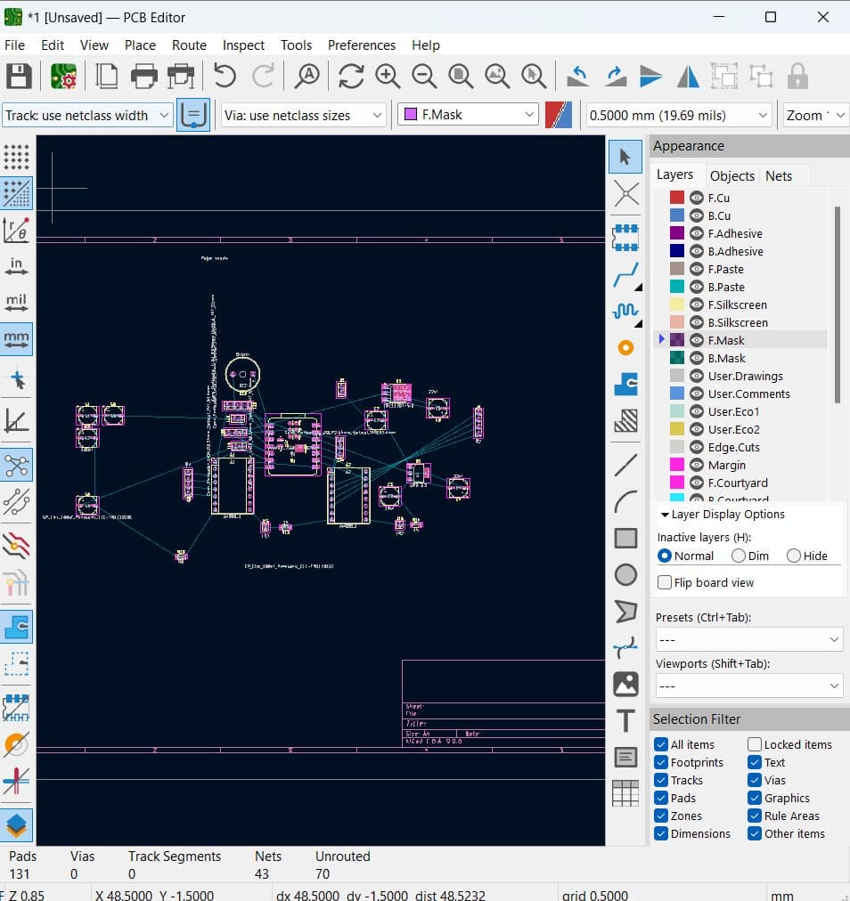
Traces
- I started by arranging my components.
- Then, I added the connections and untangled the components.
- To calculate the minimum track width, I considered the total current of the , which is 1.5A. Using this value, I calculated the minimum track width in the KiCad calculator and the established value was 1.4.
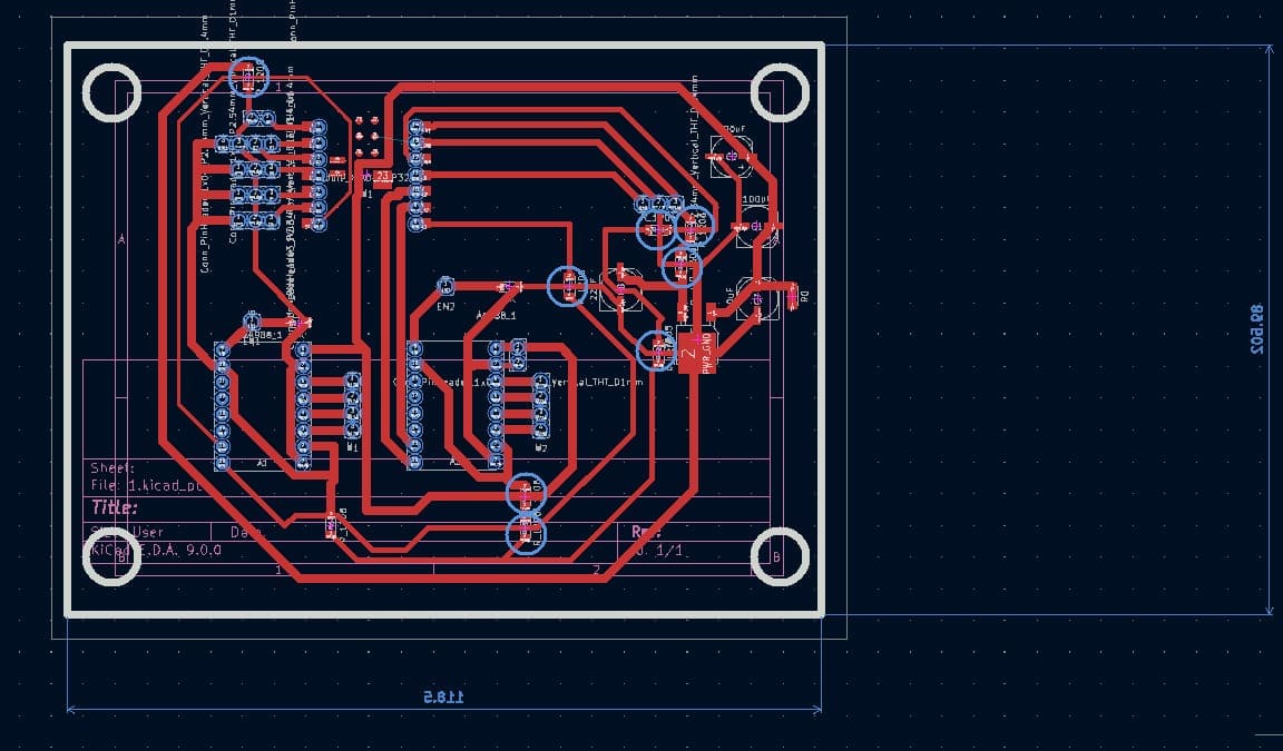
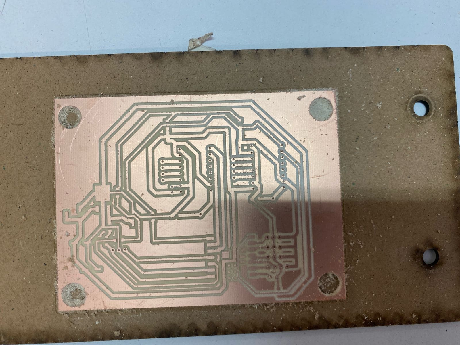
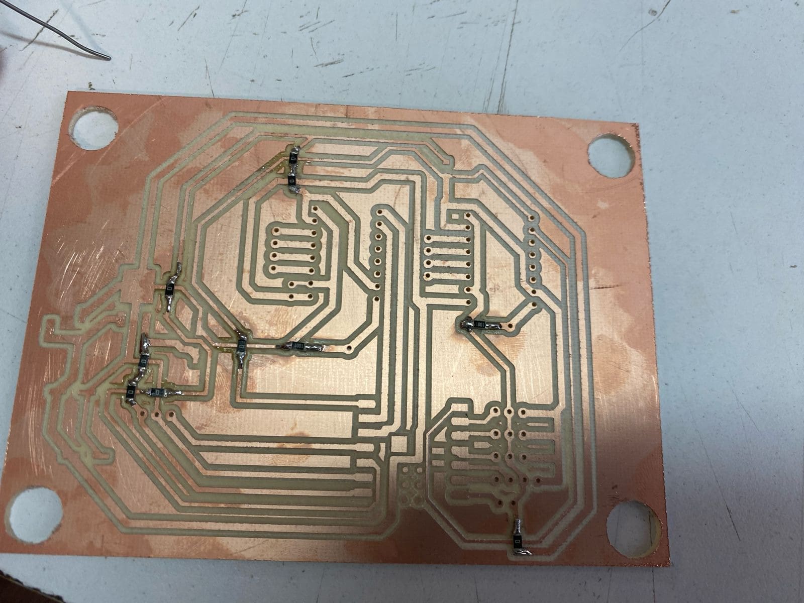
- This is my final PCB.
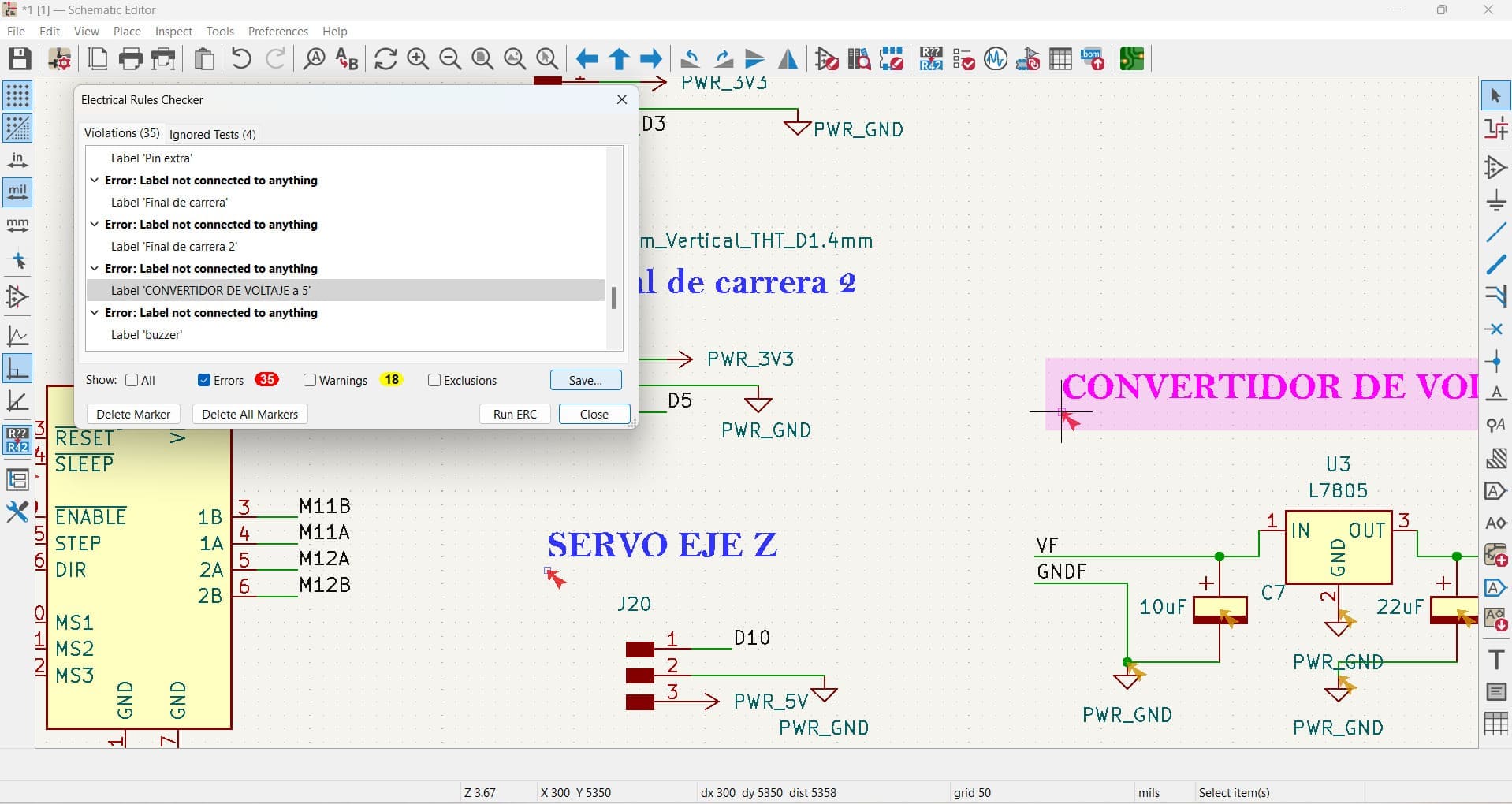
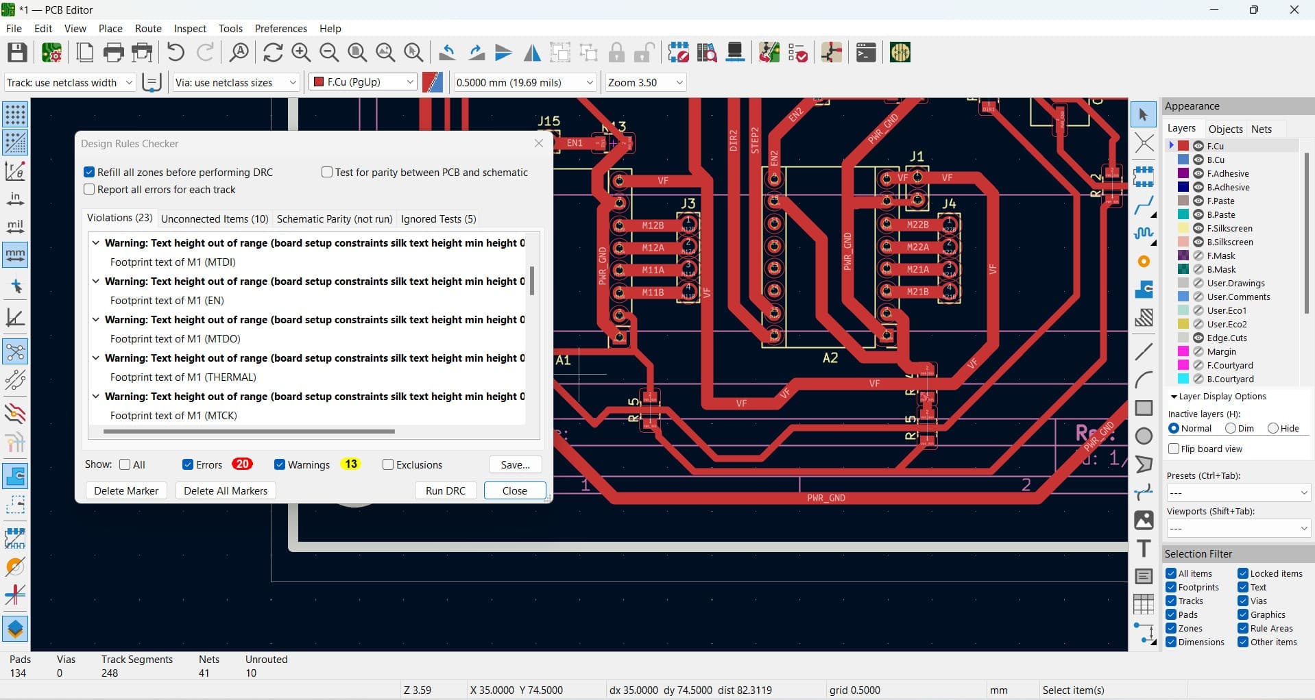
- Finally, to check everything, I used the DCR.
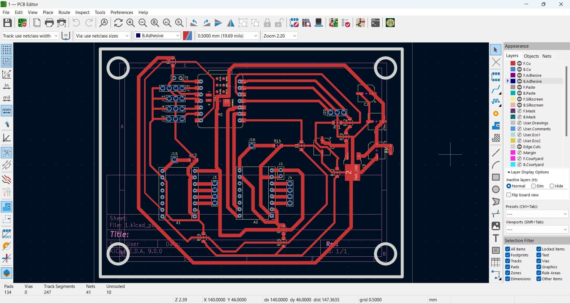
In the PCB, I marked the bridges that I used to connect the components. To make these bridges, I used 0-ohm resistors.
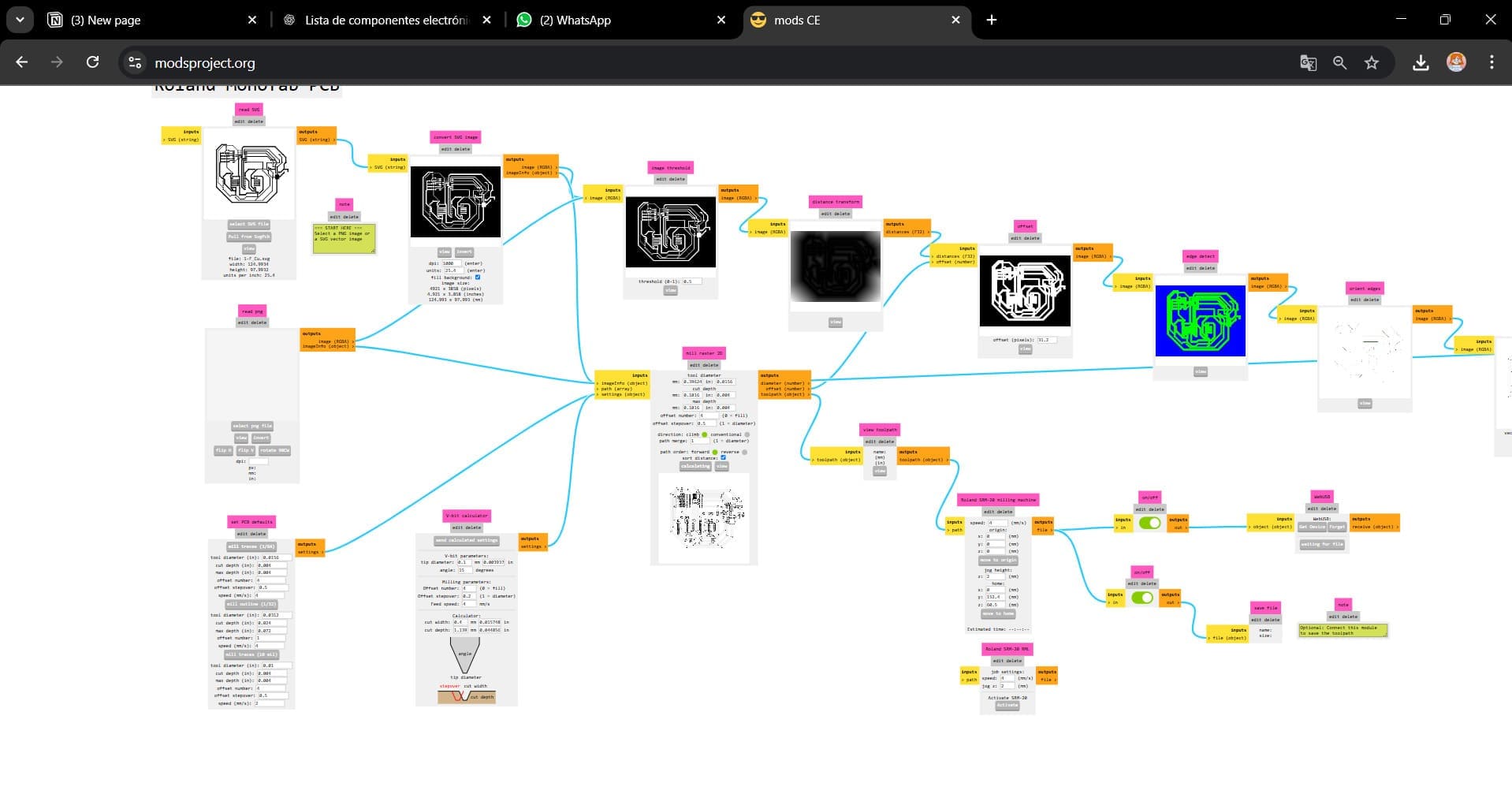
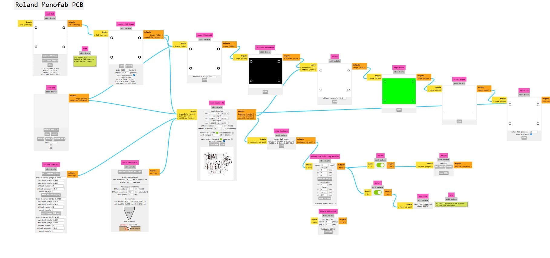
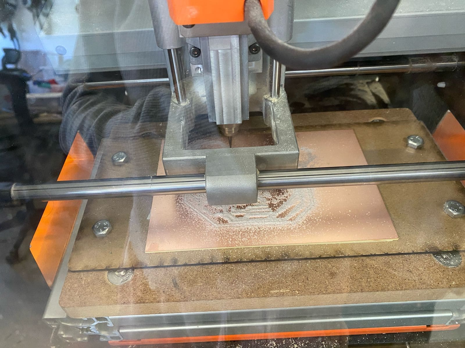
Using the MonoFab
First, I drilled the holes, engraved the PCB, and cut the contour. To see the specifications, you can check my Electronics Production task.
Holes
- I added my SVG file.
- I specified the action that I was going to perform. In this case, I wanted to cut the holes, so I used Mill Outline.
- Then, I calculated the parameters, considering that the tool diameter was 0.8 mm.
- I set up the speed. I set it to 2 mm because the cut was small, and I considered that the best option was to lower the speed.
- Finally, I established the X, Y, and Z axes as 0, and I slid the button below so that the program would create an RML file.
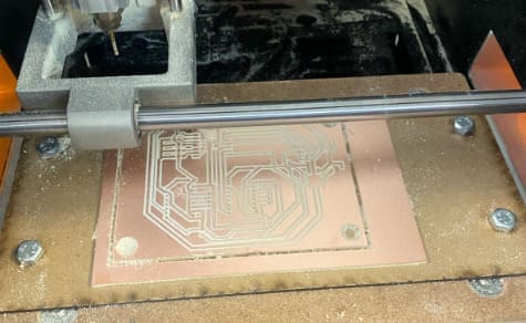
traces
- For the traces, I inverted the image to the machine will engrave the black part and leave the white part high (the tracks)..
- I set up the action (In this case, it was “mill traces”).
- I calculated the parameters, and I checked that the speed was set to 4 mm/s. I established the axes as 0.
- In this case, the value of 4 indicates that 4 additional paths will be generated, which is useful for cleaning a large area or ensuring that material is removed efficiently.
- Z: 2mm so that when the tool is moved it does not break the material or the tool.
External cut
- To do the external cuts, I set up the same as for the holes.
- First, I inverted the cuts, but when I cut my PCB,it did 2 cuts . However, I left a margin, and this didn’t affect my PCB.
Soldering
First ,I soldered the resistors like a bridges and then the other components.
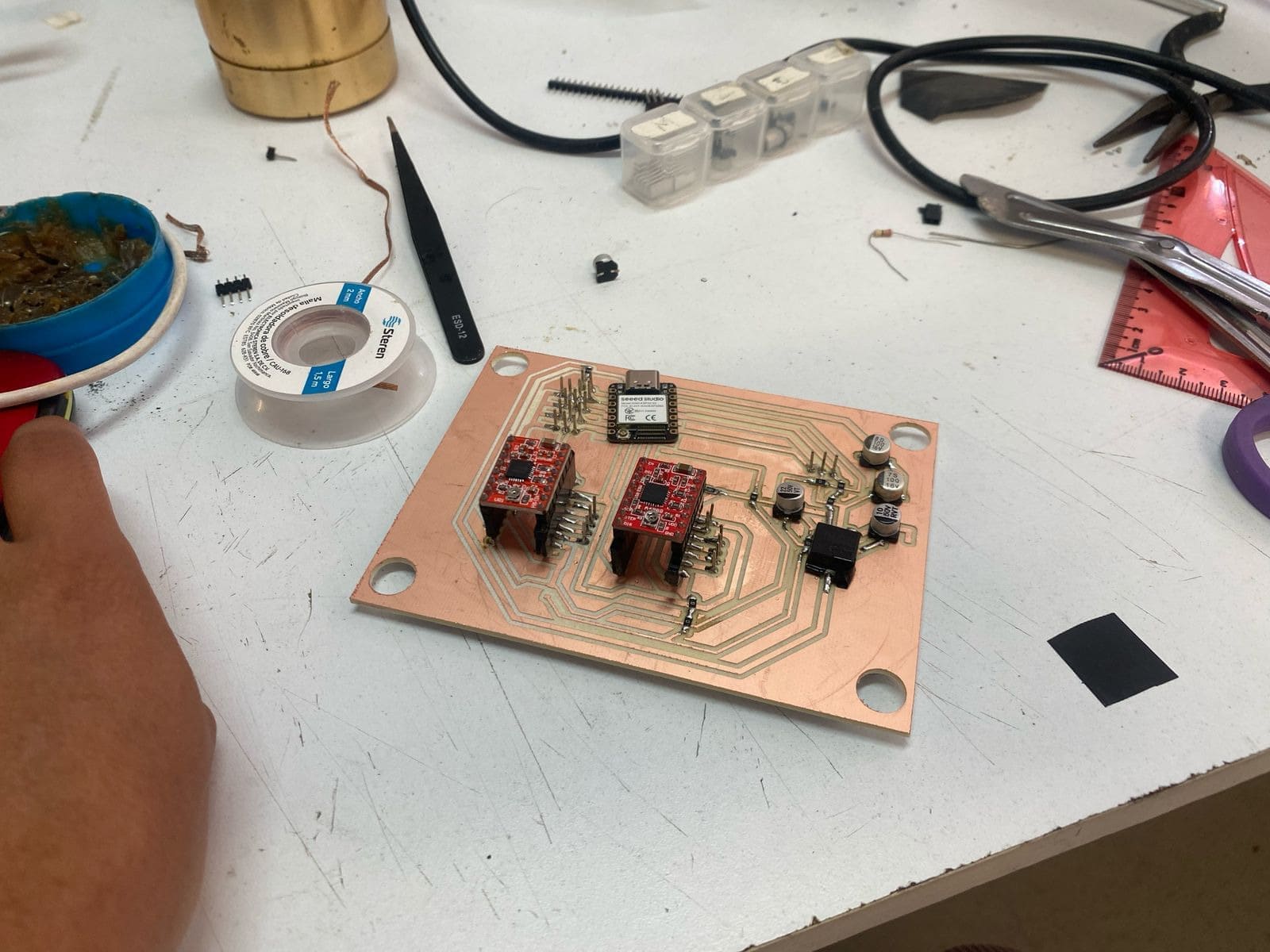
Time to do the tests
I was nervous because I didn’t know how the PCB would react, so I started by moving a servo. Then, I moved the motors.
This is the code for the stepper motors:
#define STEP1 6
#define DIR1 7
#define STEP2 8
#define DIR2 9

void setup() {
pinMode(STEP1, OUTPUT);
pinMode(DIR1, OUTPUT);
pinMode(STEP2, OUTPUT);
pinMode(DIR2, OUTPUT);
}

void loop() {
// Motor 1 - Una vuelta completa (400 pasos en 1/2 paso)
digitalWrite(DIR1, HIGH);
for (int i = 0; i < 400; i++) {
digitalWrite(STEP1, HIGH);
delayMicroseconds(800);
digitalWrite(STEP1, LOW);
delayMicroseconds(800);
}

delay(1000);

// Motor 2 - Una vuelta completa (400 pasos en 1/2 paso)
digitalWrite(DIR2, LOW);
for (int i = 0; i < 400; i++) {
digitalWrite(STEP2, HIGH);
delayMicroseconds(800);
digitalWrite(STEP2, LOW);
delayMicroseconds(800);
}

delay(2000);
}
Some Complications with the final code
- Most boards have a switch to choose whether they are powered by an external source or by USB, in case both are connected at the same time. But the XIAO doesn't have one, so what happened was that we powered the XIAO with both the external source and the computer, and the XIAO burned out.
- However, the rest of the board was intact, so we had to solder a new XIAO. We also cut the 5V power line from the external source to the XIAO and only kept the power from the computer to avoid voltage issues.
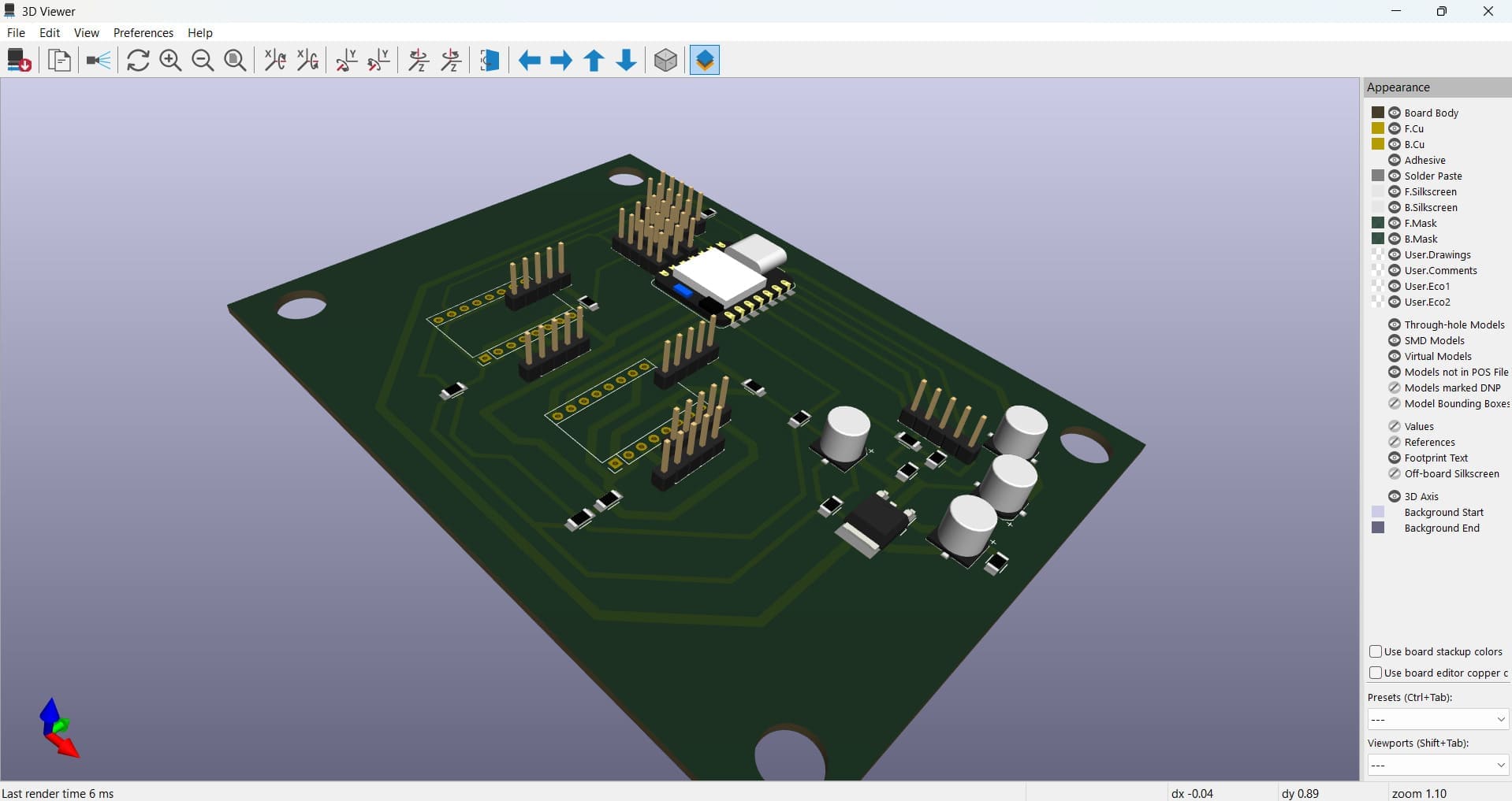
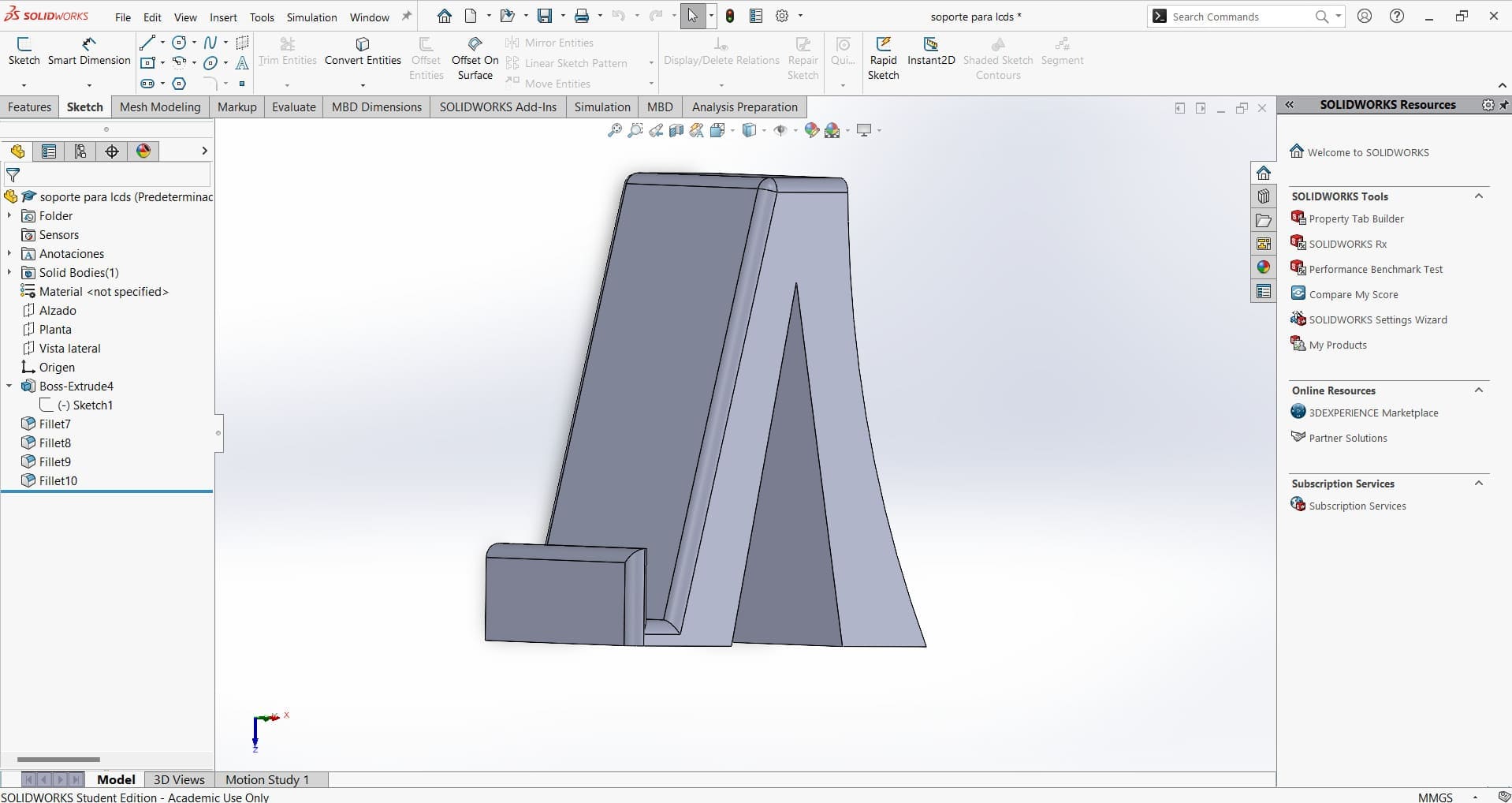
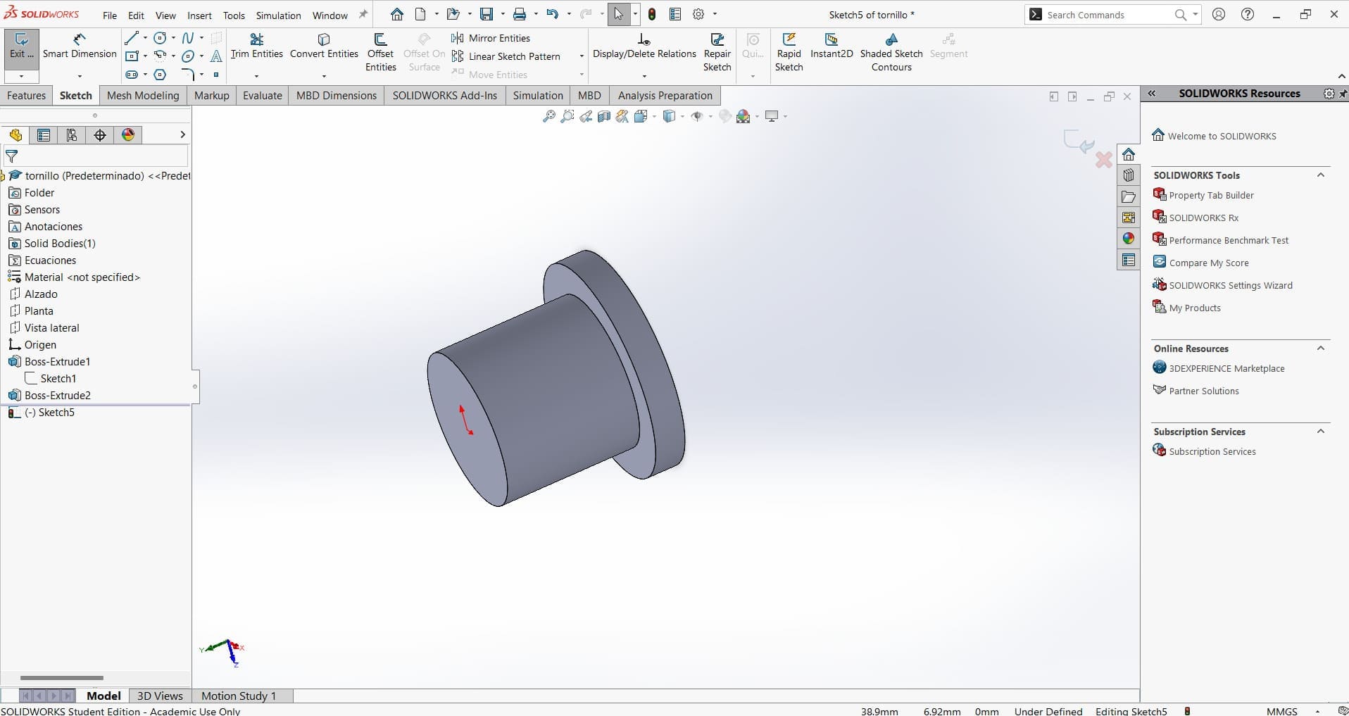
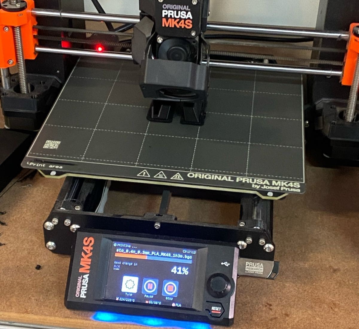
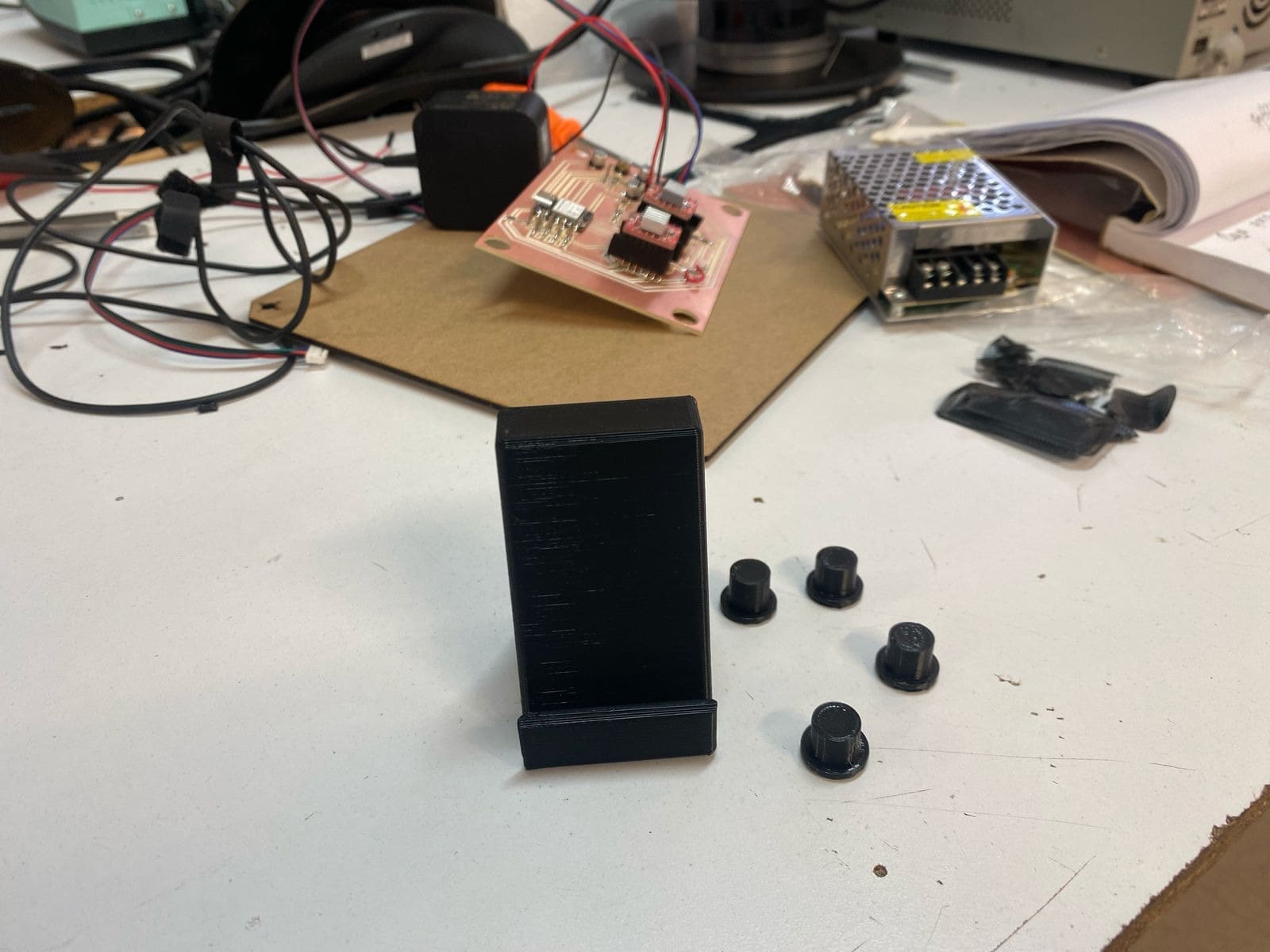
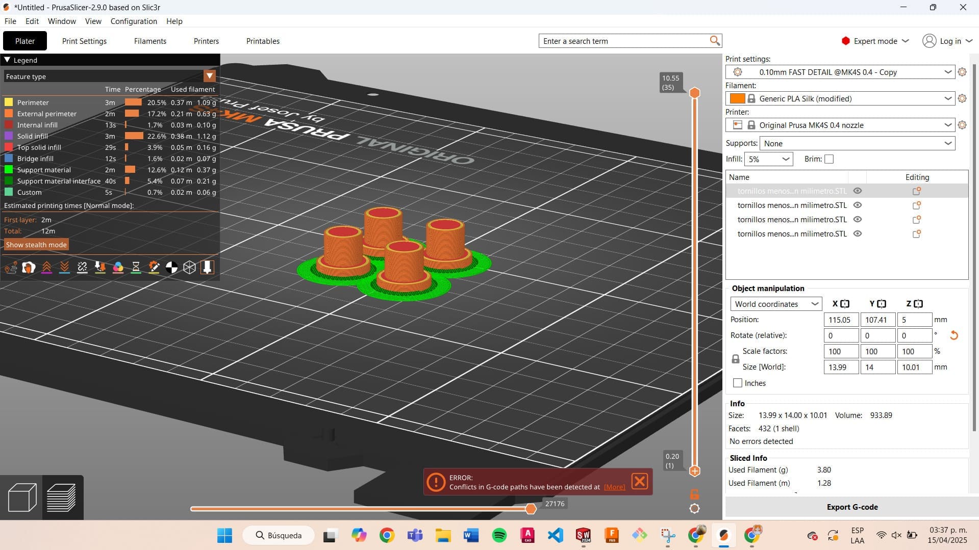
Making a Case for My PCB and the Power Supply
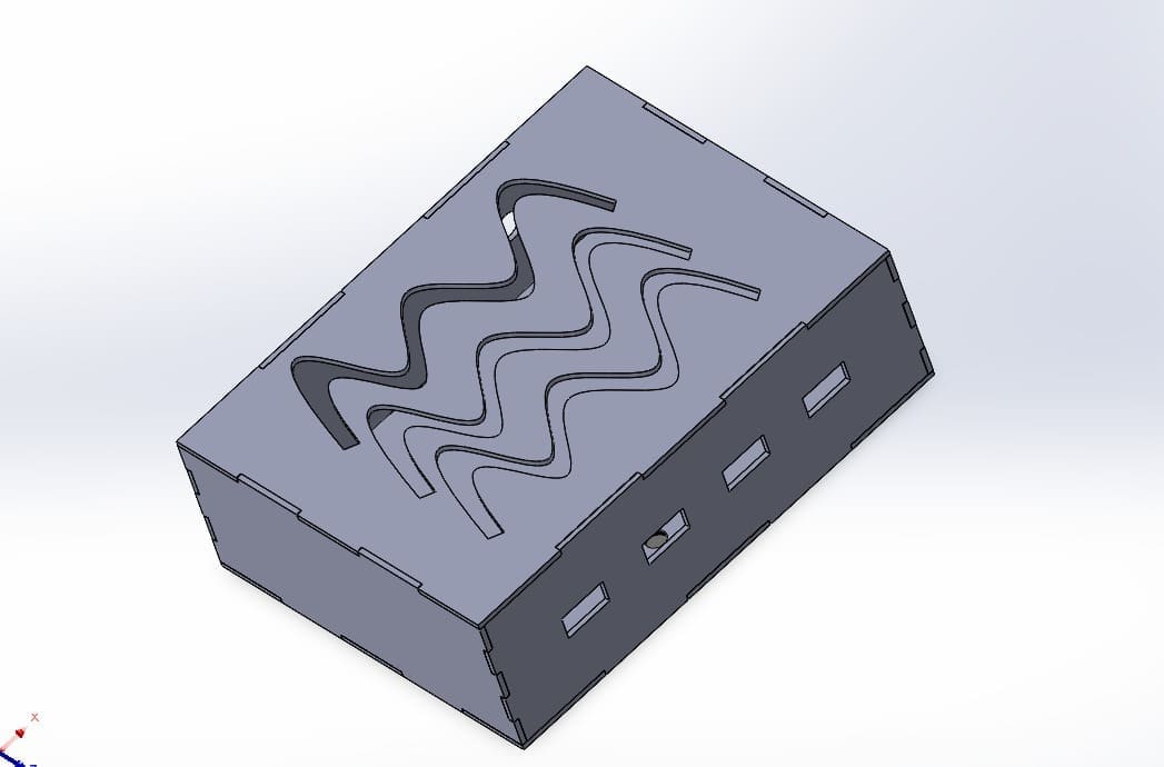
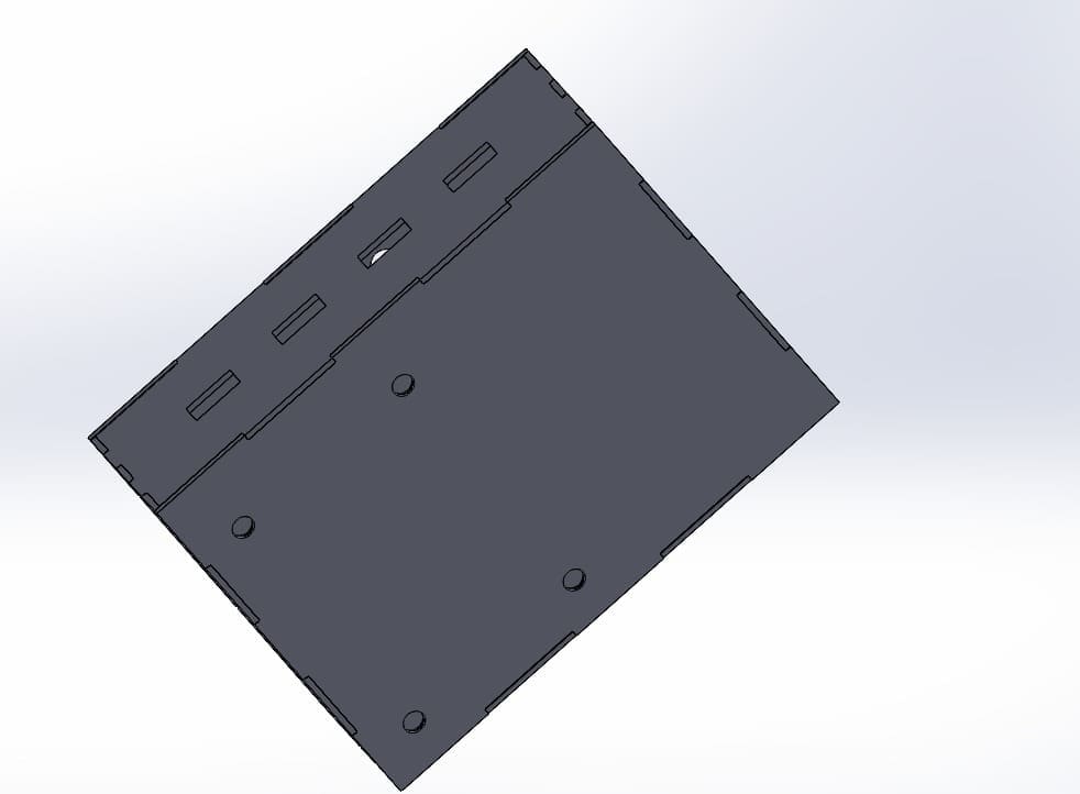
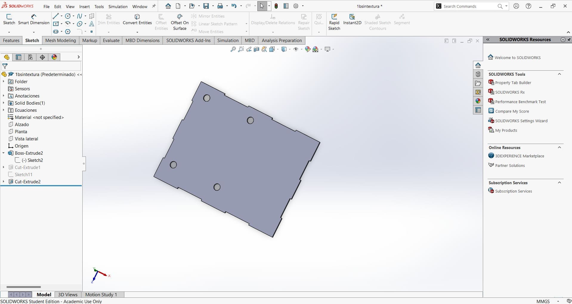
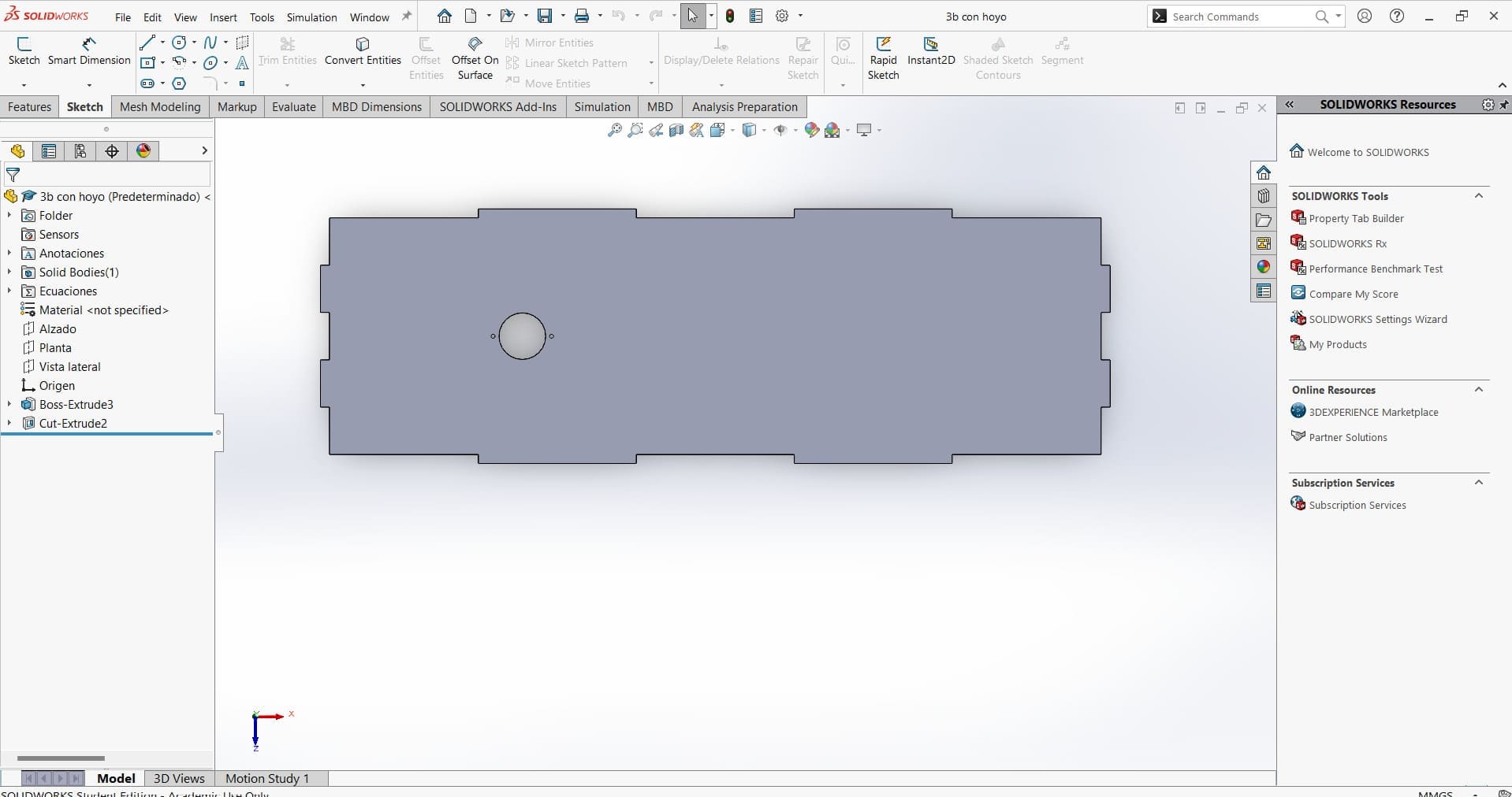
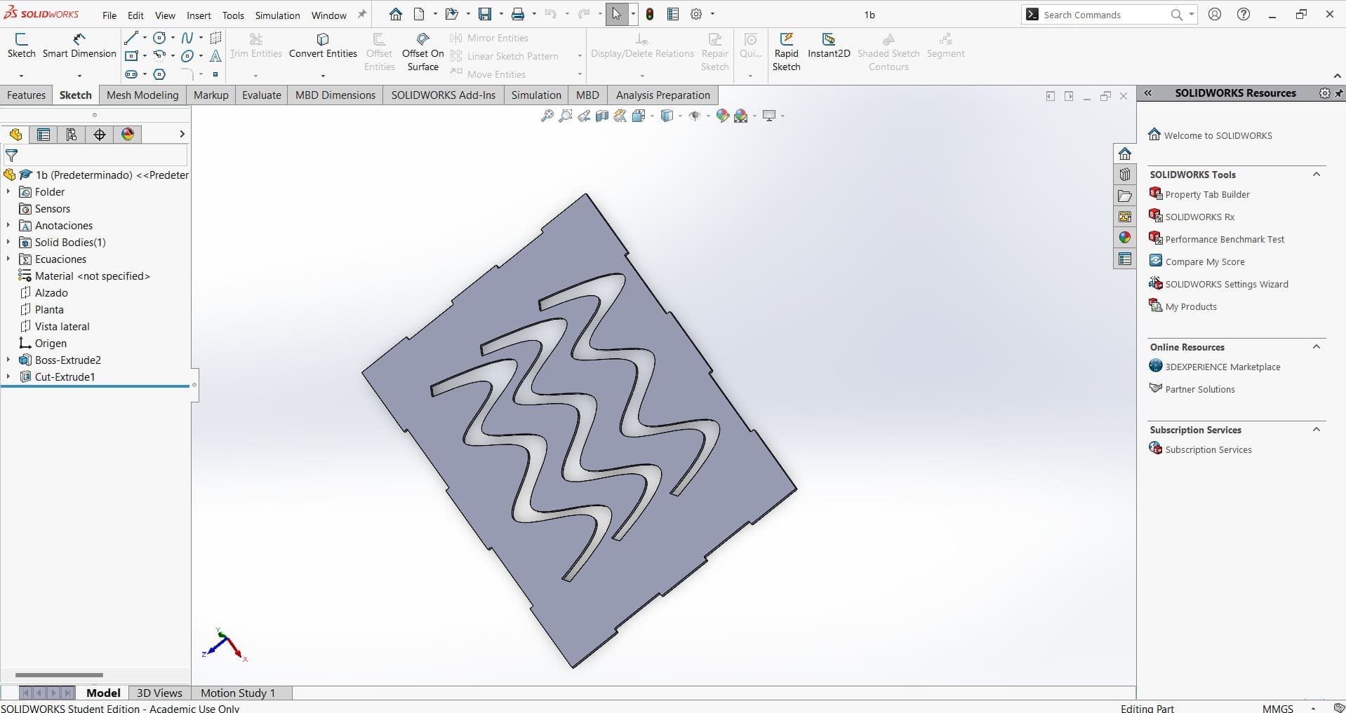
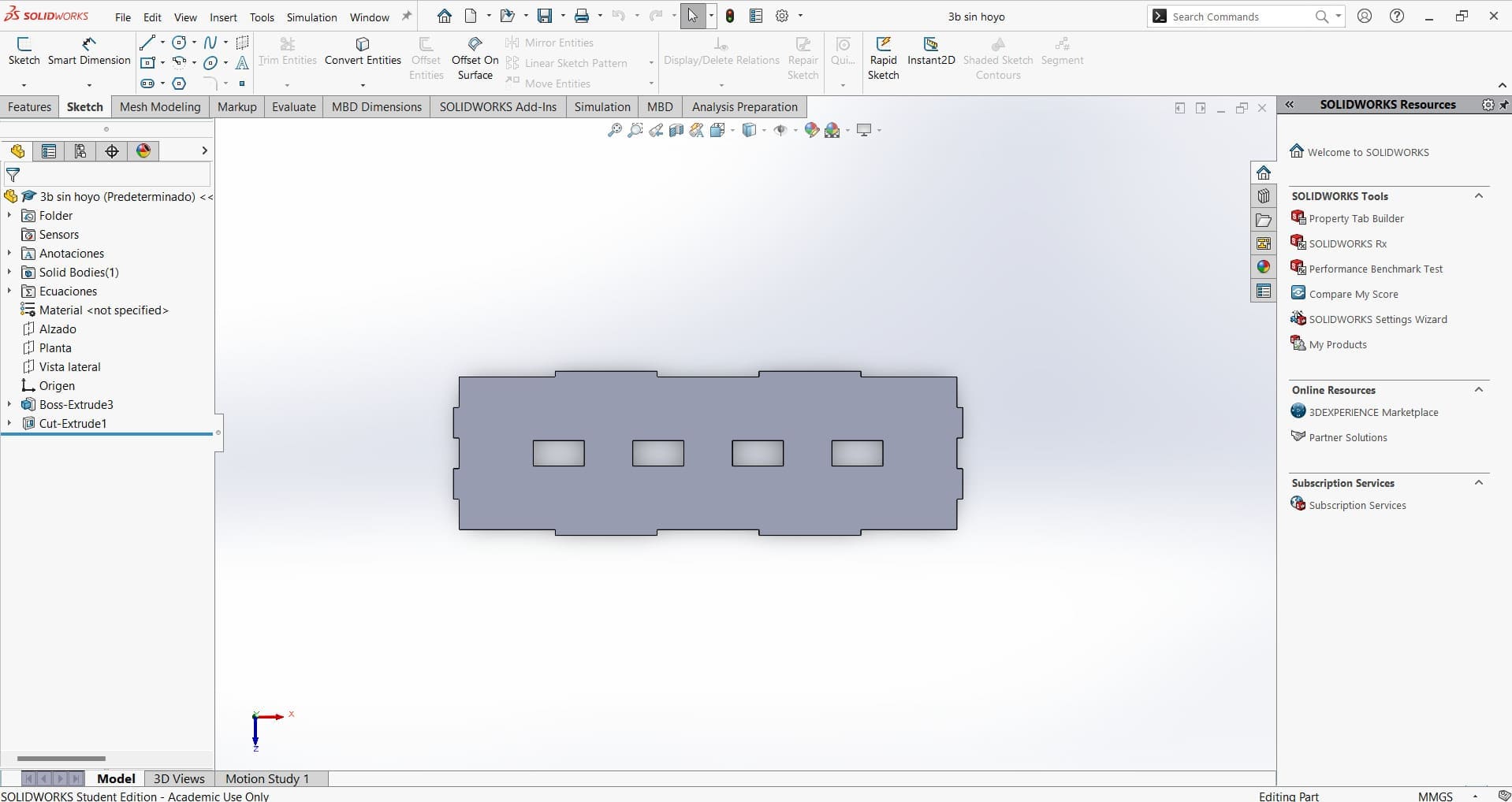
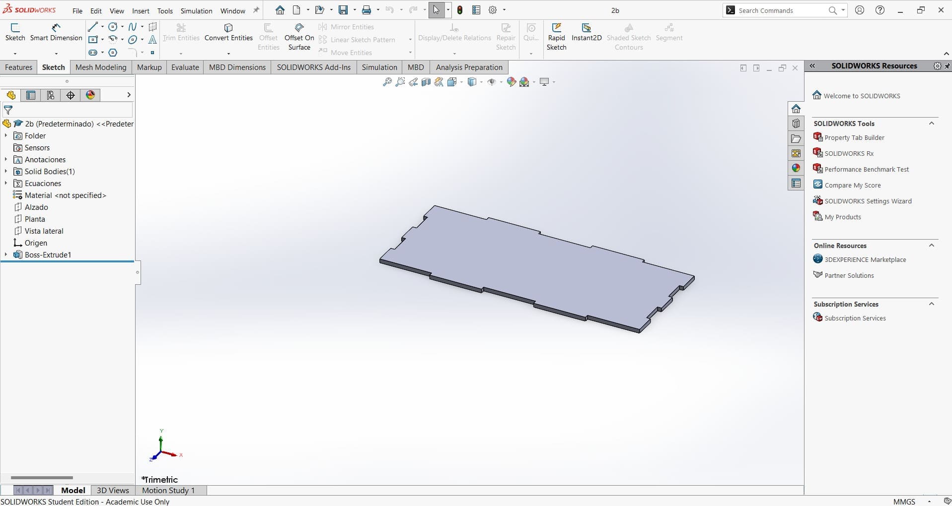
Finally, to mount the LCD, I made a 3D piece. To secure the board to the case, I made screws. I used a Prusa printer.
Files
Conclusion🛸🛸
It was a challenge to understand how a CNC works, including each of its parts and the electronic components that make it work. As a team, we also learned things we didn't know about, like the problem with the XIAO, which will be useful in future projects.