Week 12. Making a machine
But first
What we did
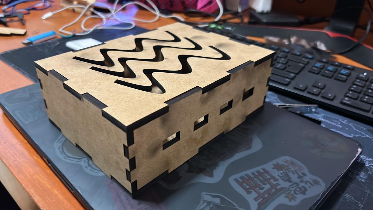
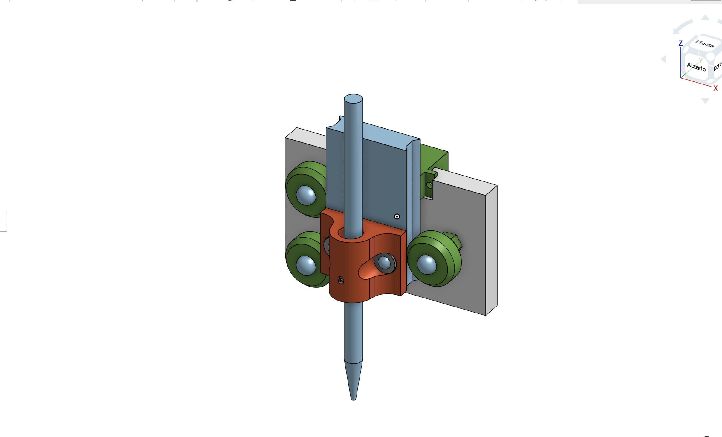
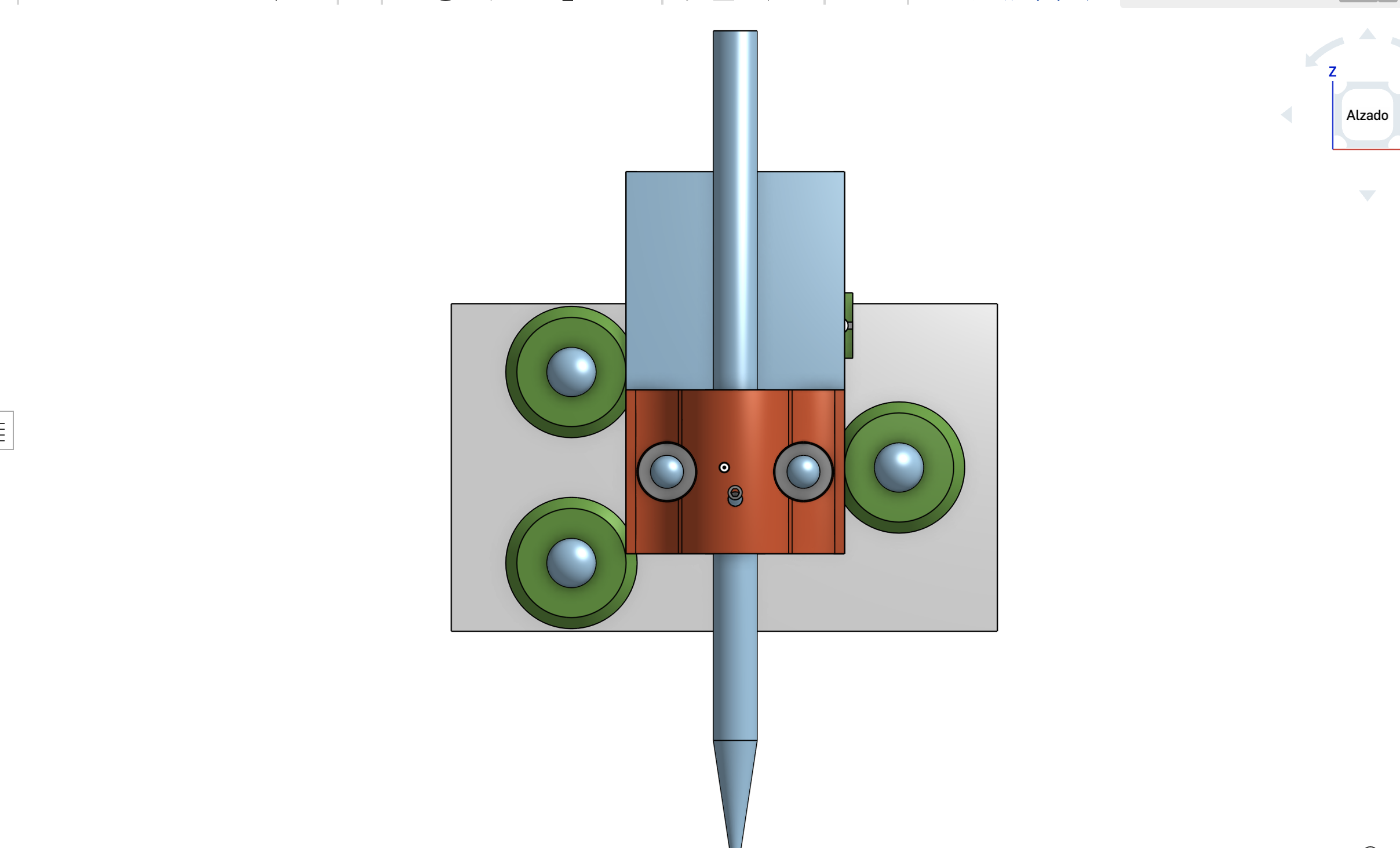
This week is about making a machine with at least 2 actuators and some sensors. My team and I decided to make a painting CNC machine, so my part is to make the Head of the machine, so I have to contemplate the support for the pencil, the slicing mechanism, the moving mechanism with a servo motor and coupling to the y axis piece. The first idea was using a worm screw but the idea was discarded because we only want to move the pencil a 1 cm as much, so the commercial worm screws are to long. That's why the decision was to use a rack and pinion mechanism. That for the moving part, for the slicing part we decided to use 4 guide bearings with inner guide. So the first prototype looked like this.
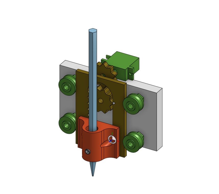
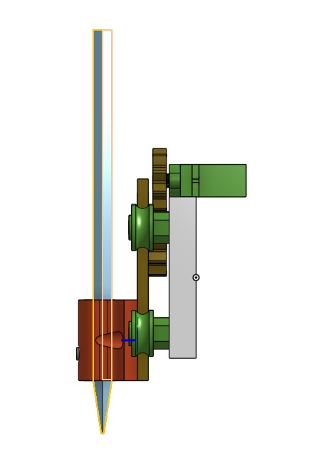
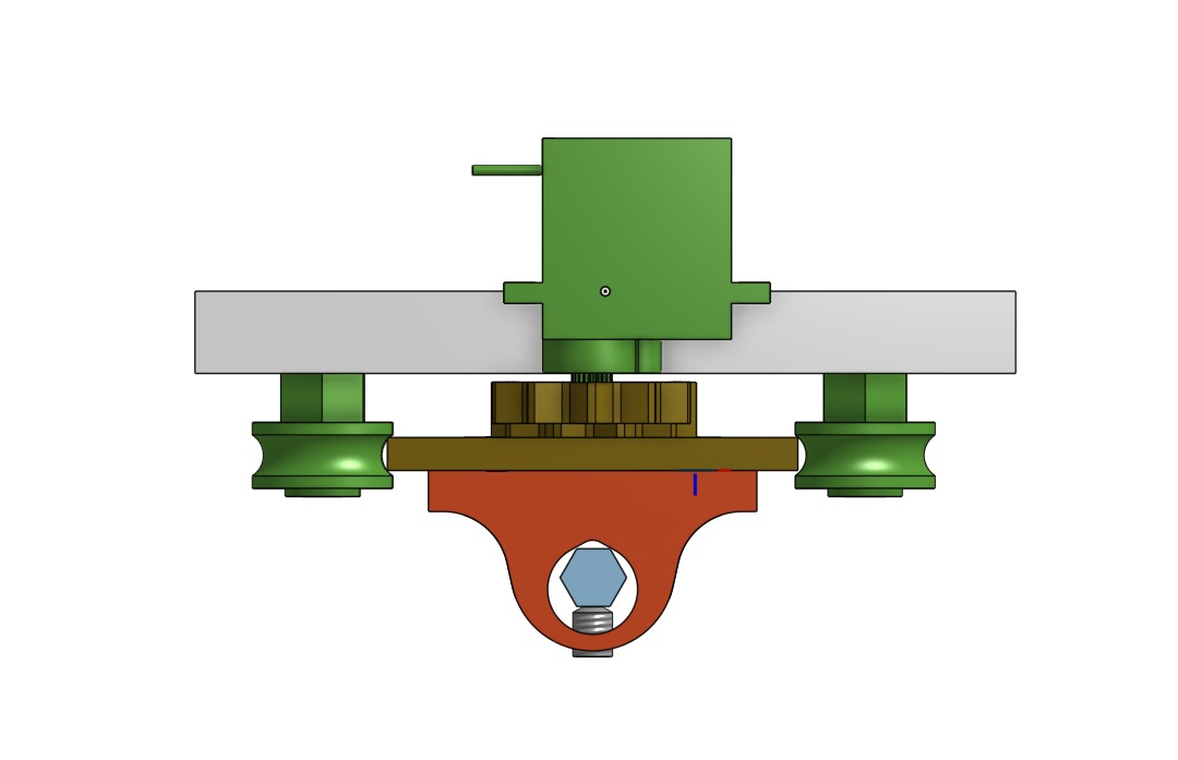
The main issue with this idea was that we don't has de pieces and we the shipment to Mexico was took a lot of time and couldn't arrive on time, so I looked at an old 3D pinter and used it's parts. The main piece got thicker so it can still roll on the guides. The idea was also to use this
So we could adjust the pressure of the bearings on the main piece.
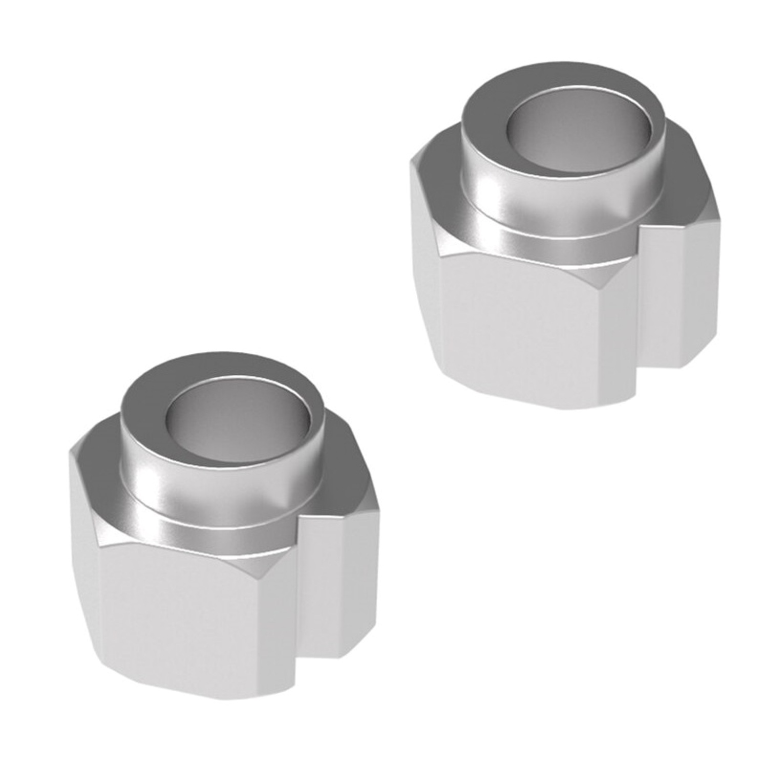
Now, as we wanted our head to support different kind of pencil with different diameters, the most logic solution was to use a set screw on a circle, however the circle was going to provide only 2 pints of support on the pencil.
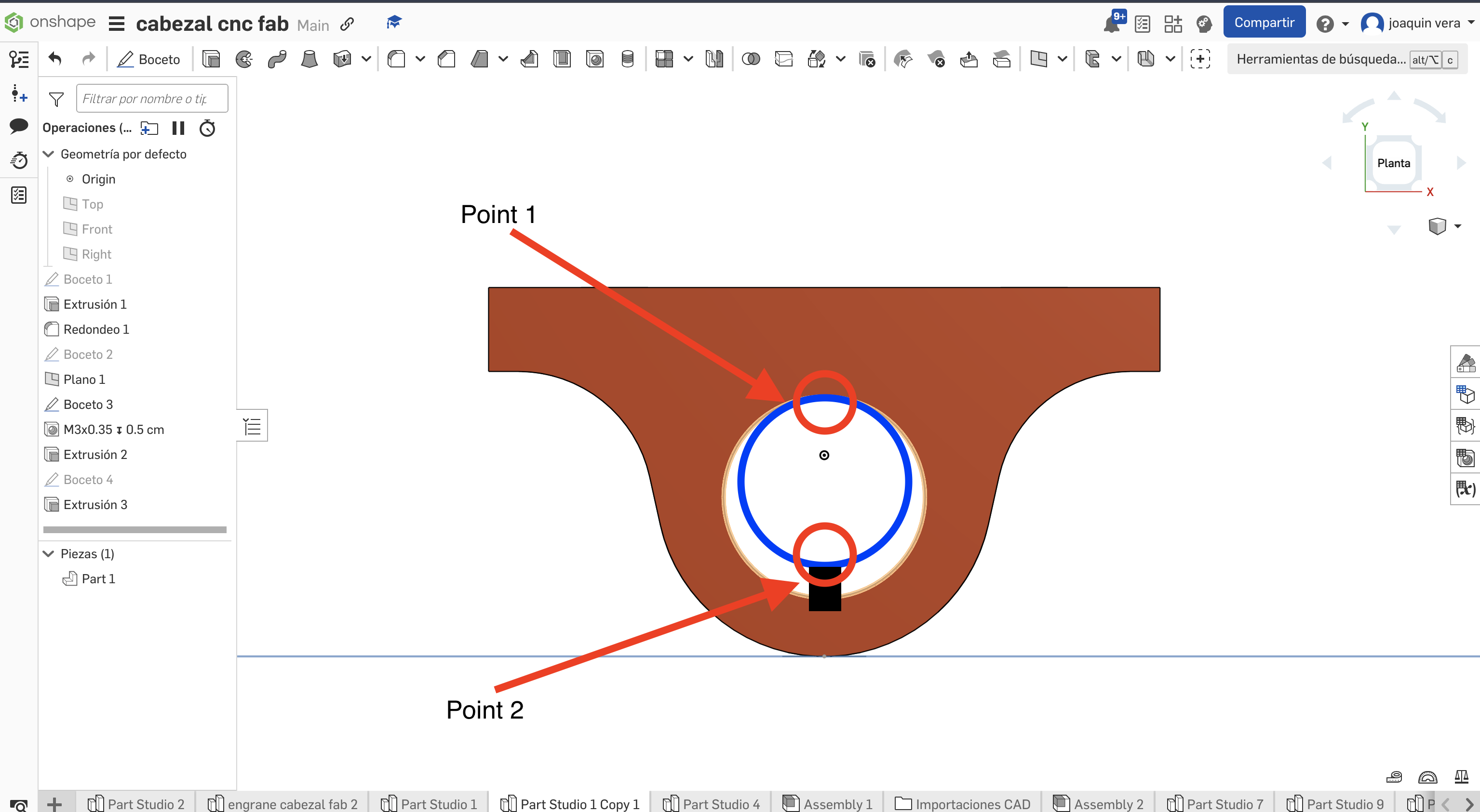
That could make the pencil to move while working so I thought about joining 2 circles (one bigger than the other) with straight lines so the pencil has 3 supporting points and it doesn't move while working.
The second thing I had to do
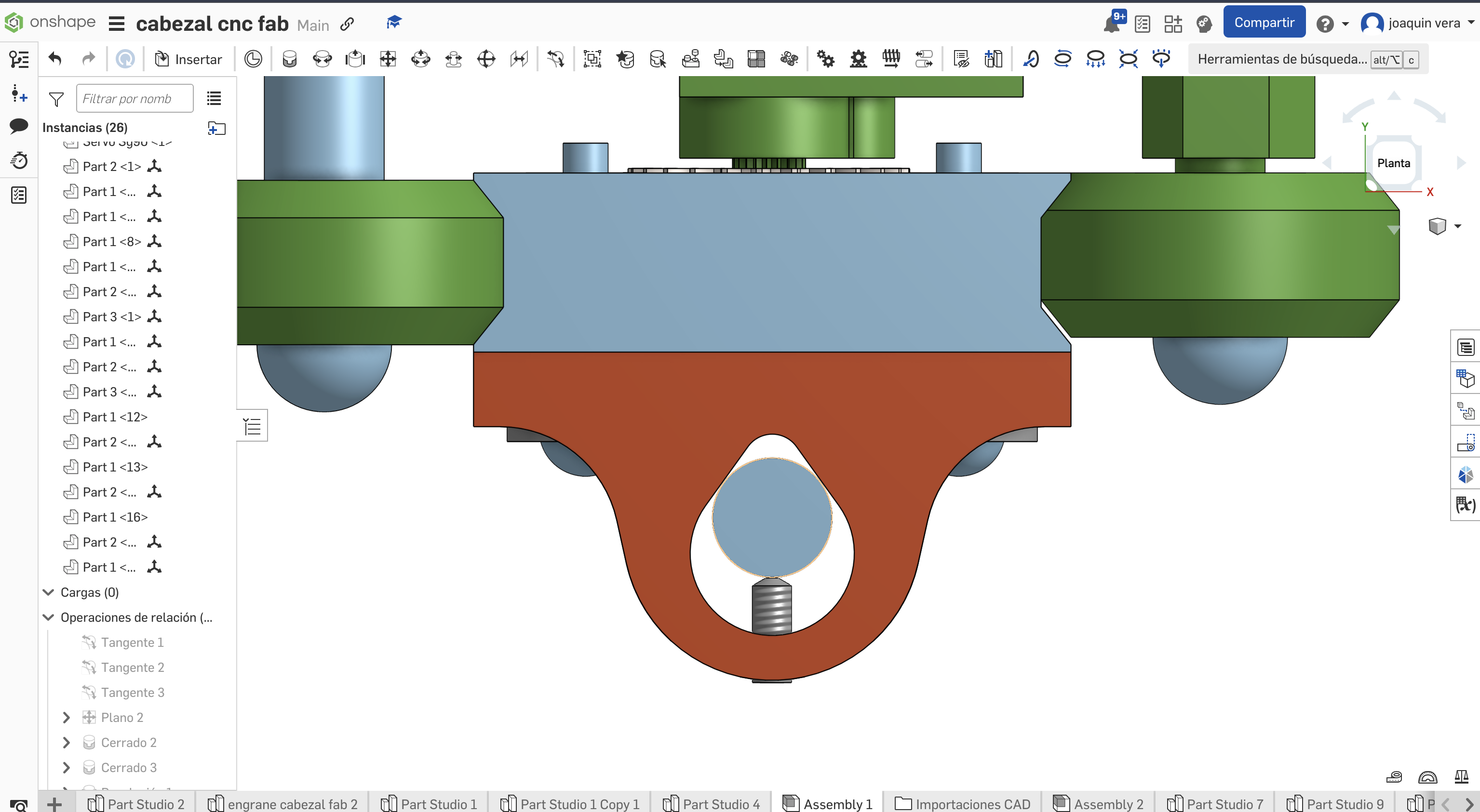
I have to say that A teammate made the original design, I just gave some values to adjust it to the machine.
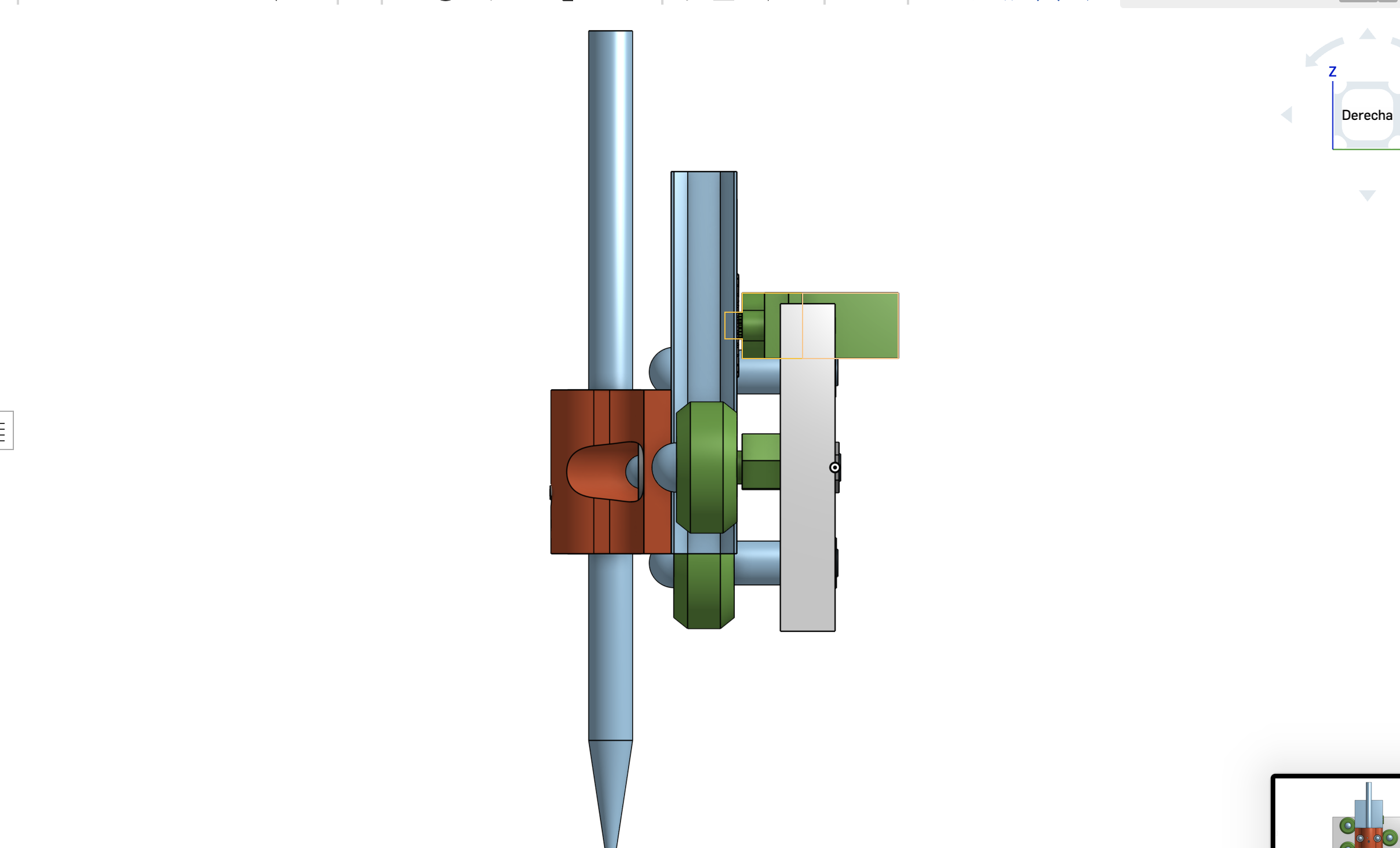
Besides designing the z axis of the machine I had to make a box for the power supply with MDF, so I had to use a laser cutter.
I used a Creality falcon 2, this one use a diode tu cut through materials, and I had to do the calibration process once again.
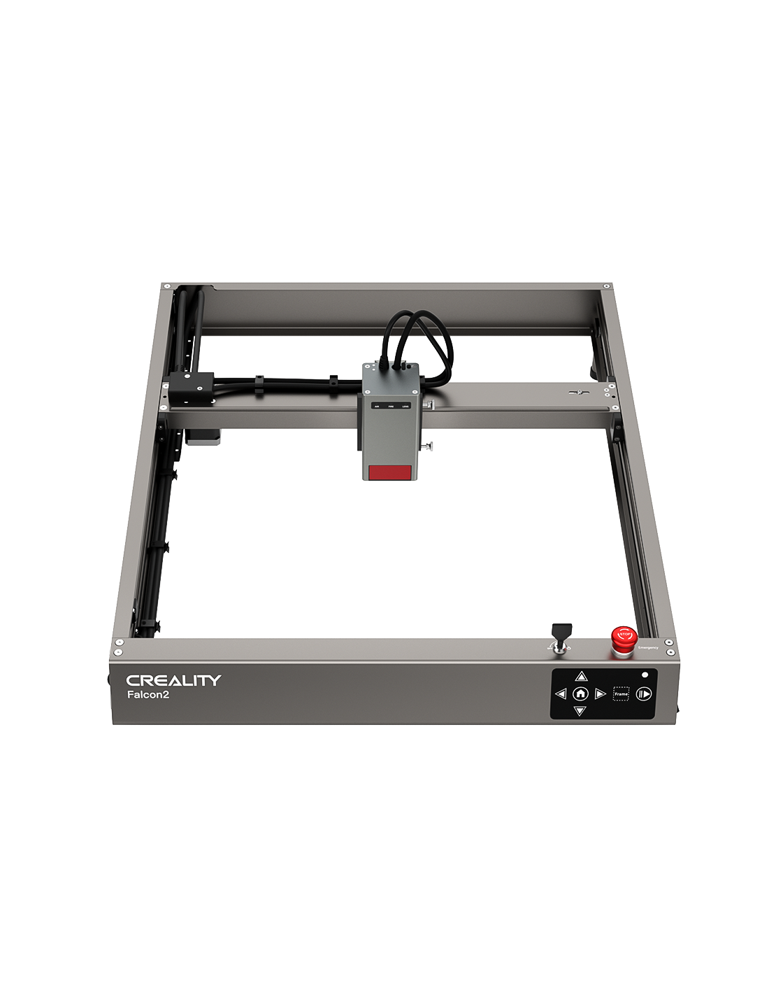
Getting the machine ready.
This machine is very easy to use, is literally just a plug and play device, once you turn it on, it will start the airflow system and go to it's home position, after a few seconds it will turn off. Now, as with the CO2 machine, we hae to adjust the head to a certain height with different thickness f the material, in this case I worked with 5.5mm thick MDF, and the distance are given by this little tool
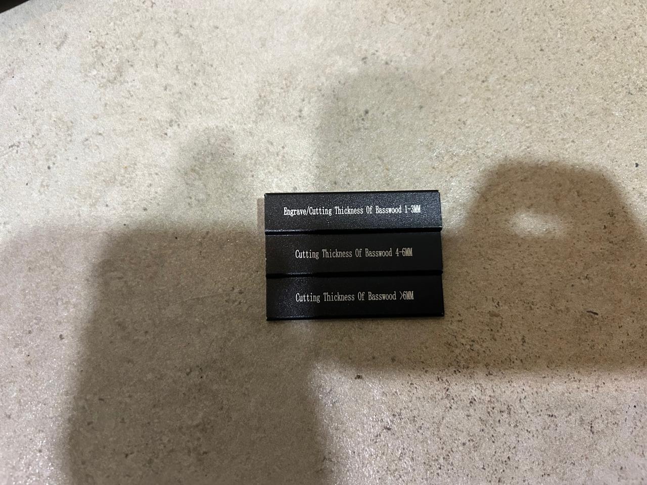
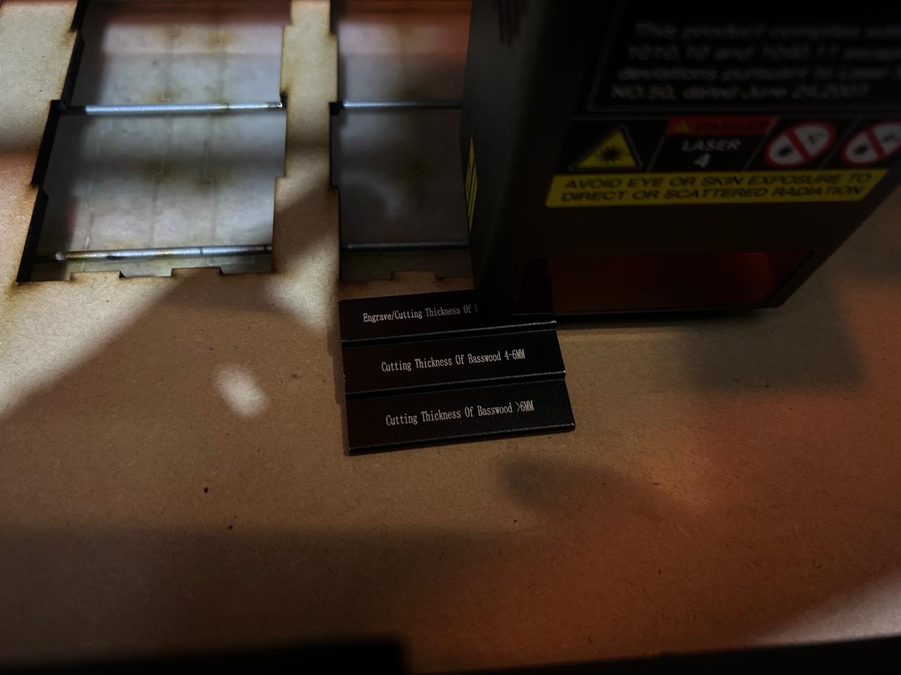
You just have to place it between the material and the lowest point of the head, you have to use the step according to the thickness of the material, in my case I used the middle step. The following image is just an example of how to do it, because the step is the wrong one on the image I just explained which step I had to use
Alright, we have calibrated the height, now we can connect the machine to the computer by USB and start creating the tests.
The software

To control this machine I use the software "lightburn", it is a very intuitive software and it supports this machine, so even though I have to pay each year for a license it is worth it, let me explain why.
When you just download the software and start setting the machine on the software it already has a profile with all the specifications of the machine, you just have to select it and change some other parameters.
I did this process many month ago. But you can fin more details on the installation manual on the USB that comes with the machine.
Let me explain real quick how does this work. Basically is the same we used with the CO2 laser, the vector to cut, the layers of cutting, the order of cutting, the speed, the power, and th number of traces.
Let's say that the machine is already load on the software, you just have to connect the machine and select the machine on the device selector. Once selected on the software, the head of will move to it's origin position and turn on the airflow system.
To make the test I just made a rectangle with the option on the menu on the left side of the window, gave the dimentions with the upper menu of the window, and draw the inner lines with the pencil tool, then I positioned every line at the same distance to the other with the "X and Y position" options on the
upper menu of the window. So, the rectangle and the inner lines are going to be a complete cut, it has to go all through all the material. and the letters are just a engraving process.
On the lower side of th window there will be squares with different colors and numbers, this rectangles are different layers, and we can ste them as we want, for example, I set the first black layer as the cutting layer. How do we know that?
because on the right menu of the window will be the parameters, there is the speed, power and number of traces. select the vector that will have the cut configuration click on the layer and change the parameters.
NOTE, on the CO2 laser is not suggested to use the 100% of the power, in this machine, there no much problem.
So, As I been working with this machine a couple of months I know that 3 passes with 100% at 1000 mm/min is enough to cut through 5.5mm of MDF. However this machine has one more option, it has a norma size of laser and a precise laser.you can adjust it bi clocking the button next to the lights. As the name says it the laser becomes thinner and so the kerf. But the parameters are not that enough. So I tried reducing th speed and traces and voilà, it worked pretty well. Now that we know the cutting parameters we can make the kerf and additional millimeters test.
Kerf test
First I made a kerf test only, to see if that is enough, I contemplated adding, subtracting and not contemplating the kerf value just in case that's enough to have the grip we want.

Yep. just contemplating the kerf is not enough, I have to add some extra millimeters to compensate the space, the thing here is that I don't know how many do I have to add.

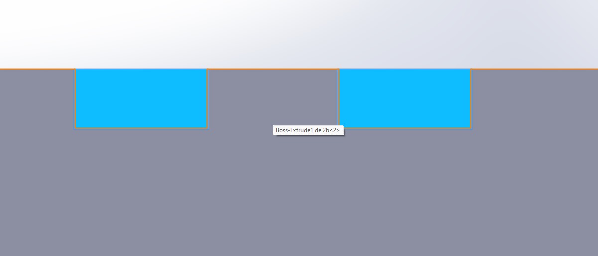
So,I made a simulations of the wall and the floor of the box in solid. Contemplating the kerf and the millimeters needed
The design
Once done, the 2mm wall didn't dit on the base, so it was the 1mm.
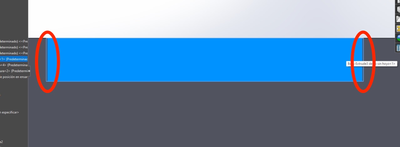
Now we just have to add the kerf and the millimeter according to the simulation, because this simulations is made so we edit just one side of the unions and not both pieces.
Note while we are adding the new measurement, on the assembly, we have to make sure that the everything is centered and each side of the "pestañas" has the same extra material.
The software Pt.2
Now that we add the extra measures to every piece that needs it we double check the assembly, so everything correct. Export each piece as a DXG file. and open each piece on the lightburn software, accommodate them in order to fit every piece on the same cut and remember to start with the inner cuts of the pieces. On this software we there are many ways of doing this, we can just put the inner cuts on a different layer, put the same parameters and place the layer that contains the inner cuts on first place.
Once this is made, we can connect the machine, place the material, ste the hight of the laser, close the protection, and make a preview of the cut
Wait of the machine to finnish
While we are waiting for the machine
This kind of machine uses light to cut or engrave the material, however this light is very dangerous if you look straight to it, so, even if the head has a orange protection, and the cover protections also has it, NEVER look straight to the laser.
Also, when working with MDF, the machine makes a lot of smoke, DON'T inhale it, use protection.
ALSO, never leave the machine alone while working, there is fire danger and even though this machine stops when overheating and make a sound, never leave it alone. ALWAYS check it.
The final Products

The files
Pieces of the head of the machine (my design)
Kerf test
Wall and base test
Final
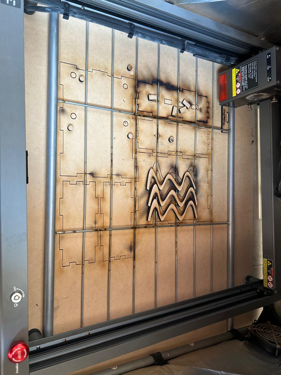
Learning outcome
Never use a cutting or engraving machine without the proper protection for the laser, in my case a protector for the laser on the floor.
I forgot placing it and my floor now has the figures I made. In this case it can be a metal plate.
Here are some examples of what happens when you don't your floor
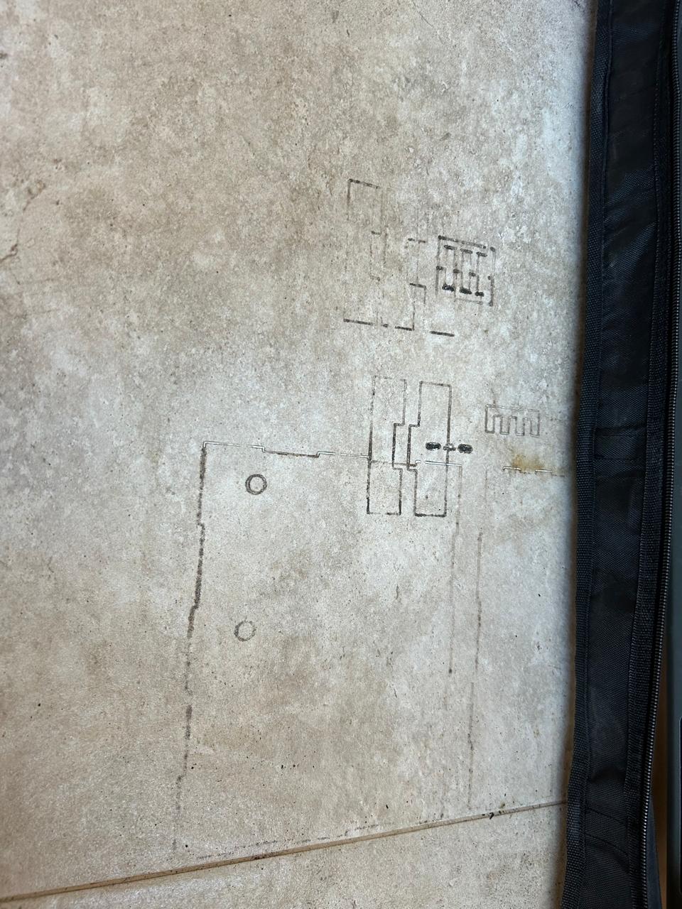
Yep, not funny, I'll be punished for ruin the floor. The good news is that I think I solved it, and here is how.