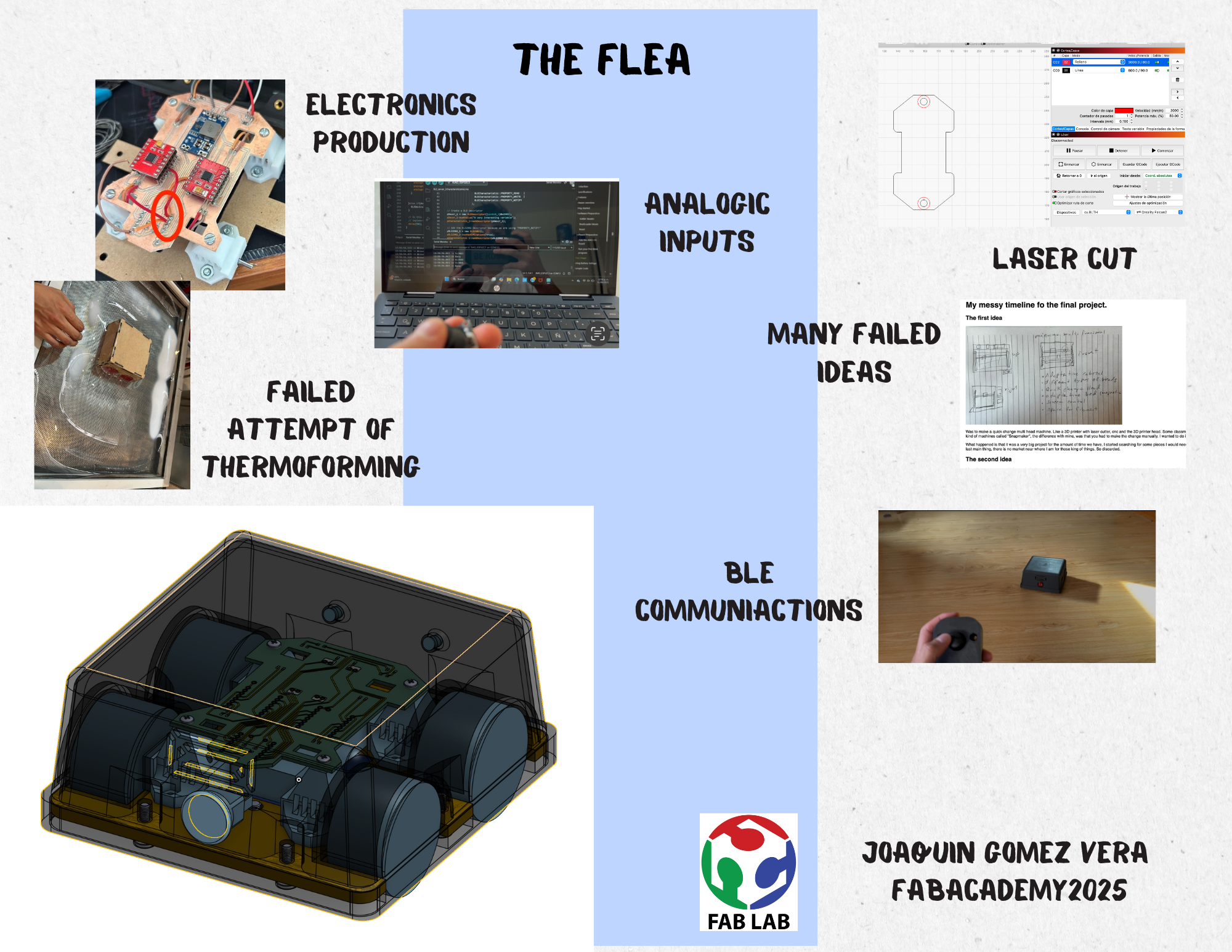
Final Project
Video and poster
My messy timeline fo the final project.
The first idea
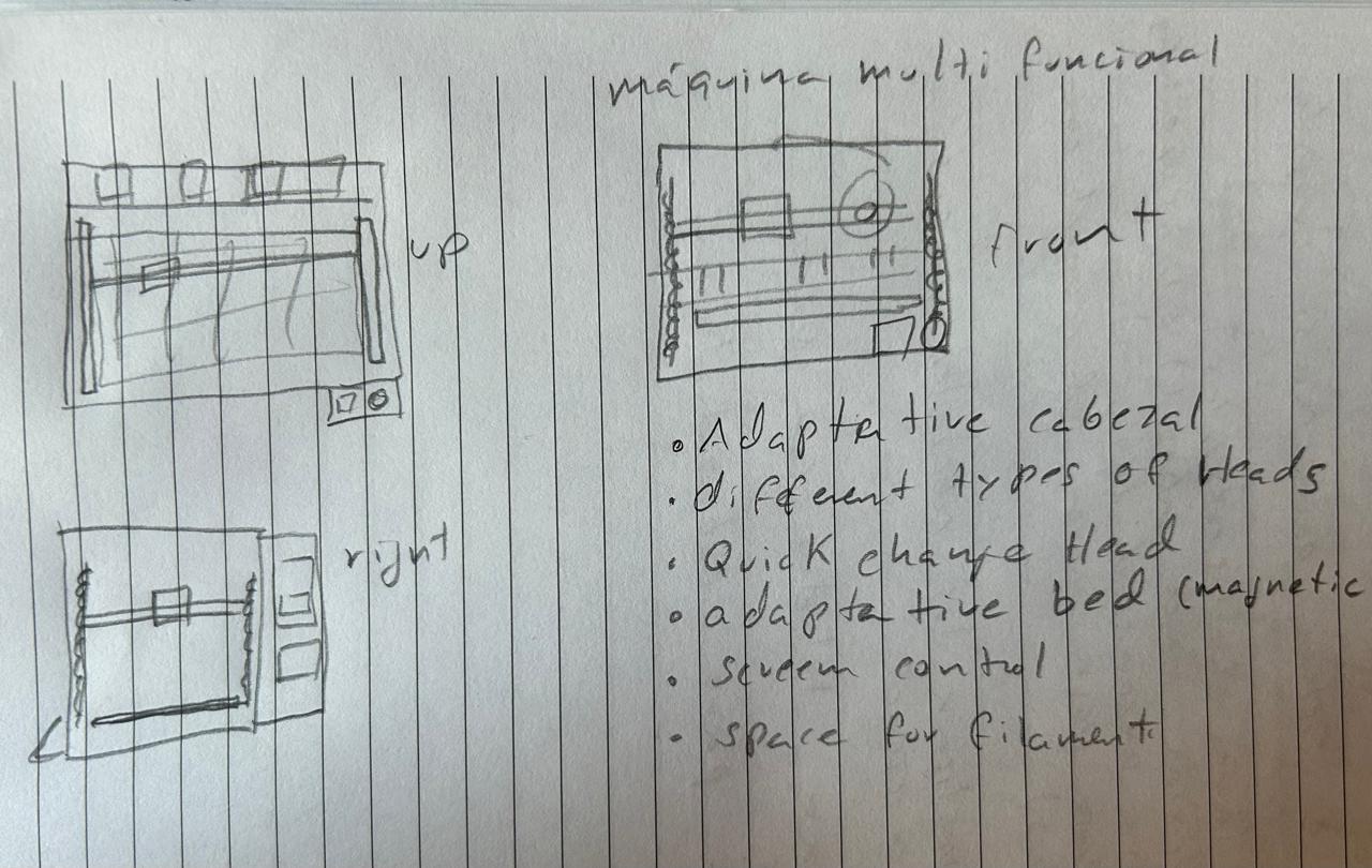
Was to make a quick change multi head machine. Like a 3D printer with laser cutter, cnc and the 3D printer head. Some classmate told me there's a company already making those kind of machines called "Snapmaker", the difference with mine, was that you had to make the change manually, I wanted to do it automatically.
What happened is that it was a very big project for the amount of time we have, I started searching for some pieces I would need and everything is already prefabricated. And the last main thing, there is no market near where I am for those king of things. So discarded.
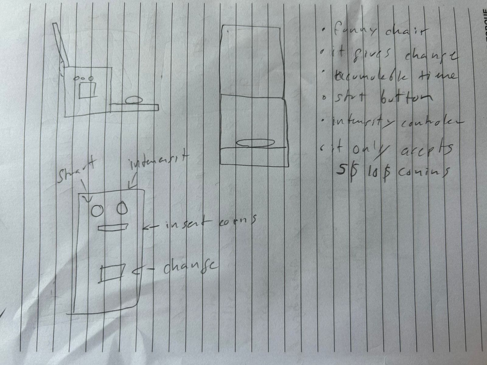
The second idea
I found some very very old funny chairs that work with vibrations on a plate on the feet, but I noticed everything was very old, and there are many ways I can renovate it, starting with the system, it works with coins and everything is analogic. The idea is to make it digital and add some more features. And renovate also the design.
The producers are footise wootsie and creative concepts, at least thats what the mother board says. I looked for them on internet and
I just found very old images.
This one sounds like a good option, I can recreate almost everything and hopefully reuse some pieces (like the metal plate).
I haven't found anything like this where I am and there are potential final users than just me. BUT ooooooh, that might be too easy,
think something else.
The third idea
Alright, ¿what does industrial consumers need?, Thought about automatizing an industrial process.
There is a torque wrench calibration process that that is mainly made by hand, and operator has to repeat the same movements a lot of times,
The idea is to automatize that process.
The idea sounded good but this was definitely too easy, It was basically a motor with a
(reused) metallic structure and everything was software.
There is a specific final user and specific companies who has already made
something like this, C.S.C. Force measurement, INC. and Norbar Torque tools.
With this was also the idea of making a torque transducer with its data collector. That might be too difficult
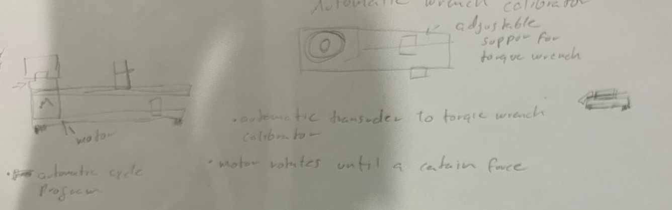
And still not decided jet.
The final decision
I finally decided to do a remote control car, this car will have a fixed camera on the front so I can see what it sees so I don't have to go behind him all the time I also thought about adding some distance sensors to the rear of the car so I can now if there is something behind it. I wanted it to be kind of a race car but maybe it's better to make it a cargo cart so I can bring thing without having to go for it.
The very final decision
Research
The turning system
What do we need to make a project like this, we need a radio controller, and the car it self. The car, I want the car to have lights, a buzzer, the motors, a camera, it needs a direction and design to put everything together.
Now, Talking about the direction system, I know there are 3 main options, the regular direction, with a rack and pinion, servo motor, track, and the suggestion of my local instructor, Omni wheel.
The first option:
the rack an pinion is composed by the two front wheel connected to it with a mechanical mechanism which let the wheel rotate and turn at the same time.

Just like this one, this kind of direction is easier to program but the mechanism is kind of complex to make with out braking it on the first crash. I also would like to add that this kind of direction are usually implemented on rear-wheel drive cars, because the the turning wheel need to rotate at different speed, so with this option I would need to implement a deferential, the direction system and I would be using just one motor.
The second type of direction I thought about is the one that you can see on the tanks for example, if you want turn, you have to move just the wheels on the other side, or you can turn the side on the other side the opposite direction to have a faster turn, you can also slow the velocity on one side, to give a smaller turn. The main advantage of this kind of direction is that you can turn 360º on the same place, you don't need to make a whole circle to turn and it is almost immediate, the disadvantage/advantage is that you need at least two motor, one for each side of the car.
Now, for the last option, the omni wheel, this wheel has a very strange design but it allows you to move in different directions without really turning the car, so you can turn without displacing, you can move to a side without turning and crazy stuff. That's a curios option, the disadvantage is that is quite harder to program, and I would need a rotating camera so I can see what's going on on the direction I'm going. On the other hand, each wheel needs it's own motor, and that's what I'm looking for and the mechanism is more simple than the first one. I have to add the fact that my local instructor recommended me this option because of it's simplicity.
So with this last option the number of components and energy consume grows, but I'm looking for a 4wheel drive, and the quick turn sounds like a great option. In addition the turning camera sounds like a good challenge, and in case I couldn't finish, the car can still work without the turning camera.
The communication system
There are 3 main types of wireless communication: bluetooth, wifi , radio frequency.
However this kind of toys usually work with radio frequency, so, that's seems like a great option except for the distance and obstacle range of the signal.
This kind of signals are easily affected by the surroundings, specially if there the same signal around.
Each one has its pros and cons but the most common to work with in this kind of toys is the radio frequency, however, as the bluetooth is easier to program
and the micro controller has already a bluetooth module and not a radio frequency module and the computer works with bluetooth. I'll be working with bluetooth.
The alimentation
The first I taught when thinking about how to feed the system was a 9V battery, but I asked my teacher, if I have to divide the voltage between 4 motors and a micro controller,
the voltage won't be enough, what should I do?
My teacher told me that that kind of batteries are useless with this kind of projects because they discharge very fast and that are not design for that. He introduced me the
"Li-PO" type batteries, this kind of batteries are the one that most of the radio controller toys uses. Because
this kind of batteries won't discharge that easily.
This batteries are made of different "cells" of batteries connected in series so you have the certain voltage and current. But there is also one specific characteristic of this batteries that make them ideal.
The times they can give you that voltage and current, this feature is given by the "number"
C, that C
tells you how many times the Battery gives you the voltage and current, there are 45, 60, 75C batteries.
So, when looking for which battery to buy look for:
- How much voltage/current does your actuators need to operate
- And how much current/voltage does the drivers (in my case) support
Which micro controller use?
There are many kinds of micro controllers and the first option I thought about was the ESP32, how ever that was to big and has mani pins I won't need, so my teacher told me to use a Xiao ESP23, this is smaller and it has almost the same characteristics as a normal ESP32.
However when you look for Xiao ESP32 on internet there are to main options, the "c3" and the "s3". So let's look at the difference: Xiao ESP32 s3 maing page, Xiao ESP32 c3 main page .
When reading the characteristics of each one I realized that the ESP32 s3 is for media (audio, video,SD cards) and that kind of stuff, it doesn't have wireless communications, so, not for this very simple project.
On the other hand, the "c3" version has the communications and everything we need.
Note, while reading the specifications I found that the ESP32 c3 can be powered by a external 3.7V lithium battery, and connect the battery to a analogic pin to read the battery state.
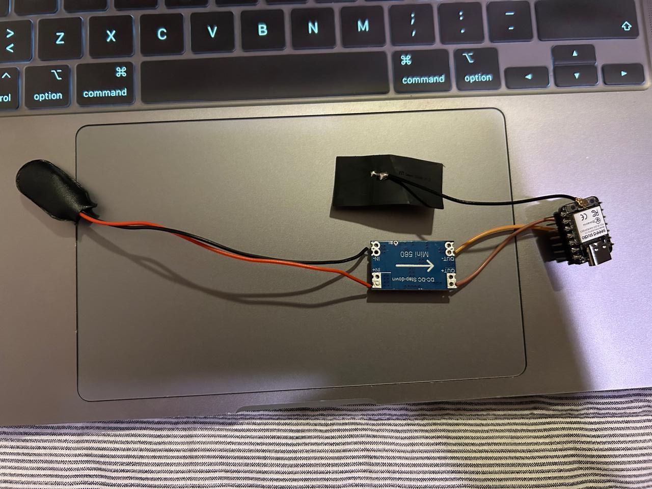
The motor drivers
The motor drivers are the thing that allows you to change the polarity of the DC motor without changing physically the cables. A great example of a driver for DC motor is the "TB6612FNG" driver. The thing with this kind of drivers is that they need 3 inputs per motor, so we would need 6 inputs just for the motors. Take a look to its pinout
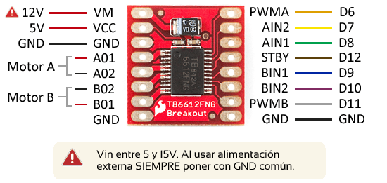
There is a analogic input for the PWM and two digital inputs for the direction of rotation, besides the logic voltage, the motor voltage, and the grounds.
This is ok when using micro controllers with many pins, but as we are limited, that's too much inputs.
That's why, once again, my teacher told me to use a different driver. The DRV8833 driver:
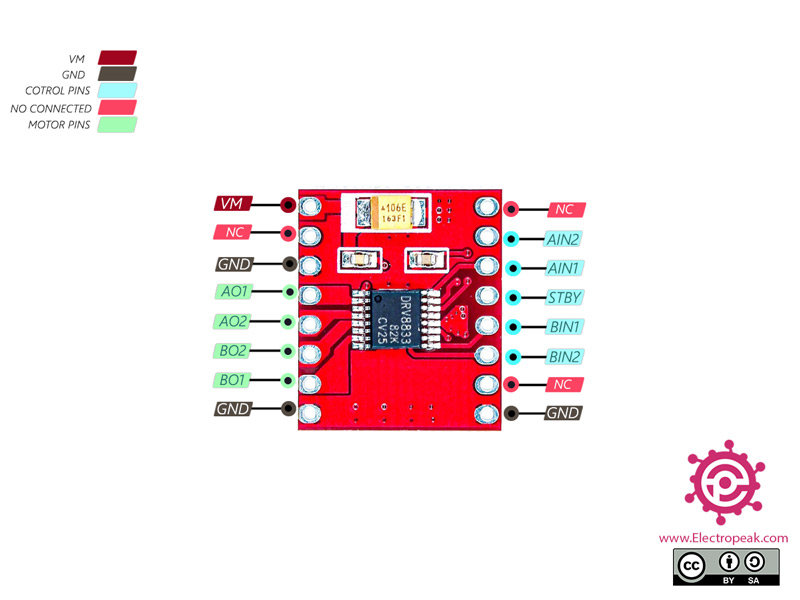
This thing uses just 2 inputs per motor, it has only one voltage input, for the logic and the motors, the grounds and the 2 outputs per motor, as this driver uses less inputs is more convenient to use with the xiao ESP32 c3 because we will be using just 2 pins per motor. Everything sounds good until the question ¿How do I program this without PWM input?". Well at least that's what I asked myself after knowing this. After a dive on youtube I found someone doing a code, You may want to take look . From that video I recovered the next code:
int motorD = 11;
int motorD2 = 10;

int motorI = 11;
int motorI2 = 10;

int velocidad = 100;

void setup() {
  // put your setup code here, to run once:
  pinMode(motorD, OUTPUT);
  pinMode(motorD2, OUTPUT);
  pinMode(motorI, OUTPUT);
  pinMode(motorI2, OUTPUT);
}

void loop() {
  // put your main code here, to run repeatedly:
  analogWrite(motorI, velocidad);
  delay(2000);
  analogWrite(motorI2, velocidad);
  delay(2000);

}
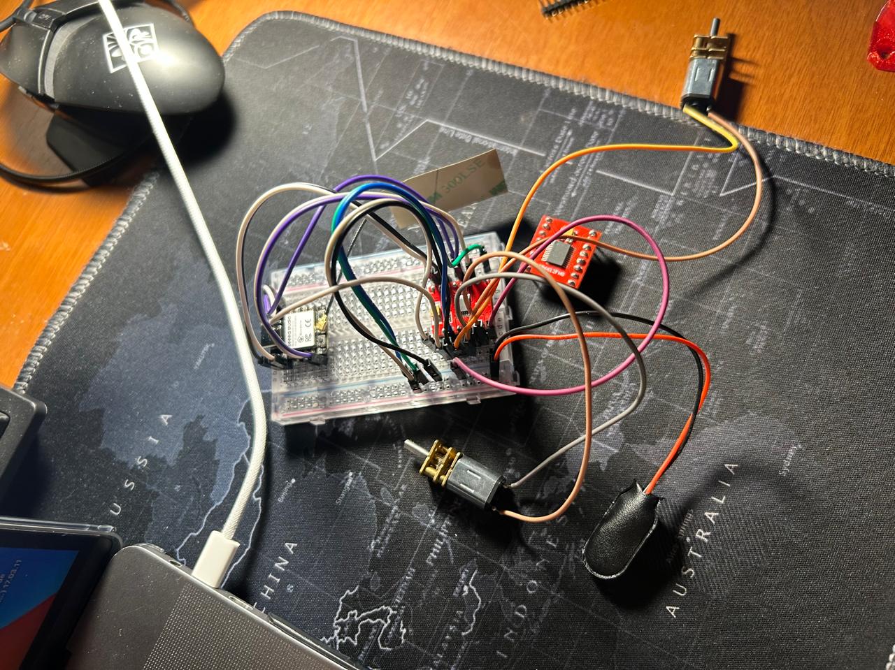
I made my circuit with just the micro, the driver, 2 motors and a 9V battery.
Note, the circuit is like this because I'm just testing.

And this came out:
So, in the code we are telling making the motor to move with just one line. With the normal drivers we tell that with two lines, because we have to set a pin LOW and a pint HIGH, but in this case we turn just one pin HIGH, and the driver know that the other one is just LOW. This allows us to set the velocity and turn on an easier way.
NOTE, I tried connecting the pins on a digital pin of the xiao, to see if it still work even if it's not an analogic pin, and it does, so we don't need necessarily analogic outputs. That's really good because the xiao has only 3 analogic pins.
The communication
The first ideas was to make the car talk with a computer, because my teacher recommended me a project, but there was a huge issue, they were using a Bluetooth module and I'm using a xiaoesp32C6
which uses BLE, so I had to change the Idea, I tried doing a wifi server, bur I realized I couldn't use continuous pulses on the buttons, I would had to press to move and pres to stop, and that was not practical.
So, on the same week I'm supposed to present I had to create a controller so they can talk xiao to xiao by BLE.
I didn't know how to work with BLE, I just knew I needed a client and a server. But san YouTube came out with this videos:
BLE with ESP32 tutorial part 2: the client
With those those videos came out with the basic structure and knowledge of how to work with BLE. As is explained on the videos BLE works with services and characteristics. You have to define a UUID for the server and for the characteristics, the client will look for the server UUID and it will connect. Then you can start exchanging information.
Materials
| Name | Qty | Description | Price | Link |
|---|---|---|---|---|
| Batteries | 1 | 7.4V 800mAh Rechargeable batteries "li-po" | 500 MXN | https://articulo.mercadolibre.com.mx/MLM-2059343451-bateria-lipo-gens-ace-800-mah-74v-2s-45c-conector-jst-drone-_JM |
| Battery charger | 1 | Battery charger for "li-po" batteries | 225 MXN | https://articulo.mercadolibre.com.mx/MLM-3448294890-cargador-balanceador-battery-lipo-b3-2s-3s-20w-74v-111v-rc-_JM |
| DC Motors | 4 | Metal reducer motor with axis type "D" | 149 | https://www.steren.com.mx/motor-reductor-metalico-con-eje-tipo-d-6-vcc.html |
| Xiao ESP32 c3 | 1 | Xiao ESP32 c3 micro controller | 345 MXN | https://articulo.mercadolibre.com.mx/MLM-3554384136-tarjeta-de-desarrollo-xiao-esp32c3-seeed-studio-_JM |
| Motor driver | 2 | DRV8833 dc motor driver for 2 motors | Unknown | My teacher gave them to me |
| Voltage reducer | 1 | 5-12v to 3.3v reducer | 99 MXN | https://articulo.mercadolibre.com.mx/MLM-850988471-2-x-modulo-mini560-reductor-voltaje-fijo-33v5v9v12v-5a-_JM |
| ohmiwheels | 4 | Diagonal ohmiwheels | 251 MXN | https://www.amazon.com.mx/dp/B09L673ZPR?ref=cm_sw_r_apin_dp_DKHYG6BRB21JKDSVD43B&ref_=cm_sw_r_apin_dp_DKHYG6BRB21JKDSVD43B&social_share=cm_sw_r_apin_dp_DKHYG6BRB21JKDSVD43B&previewDoh=1 |
| ON/OFF button | 1 | Rocker switch 2 positions | 19 MXN | https://www.steren.com.mx/switch-de-balancin-de-1-polo-1-tiro-2-posiciones-on-off-con-piloto-12-vcc.html |
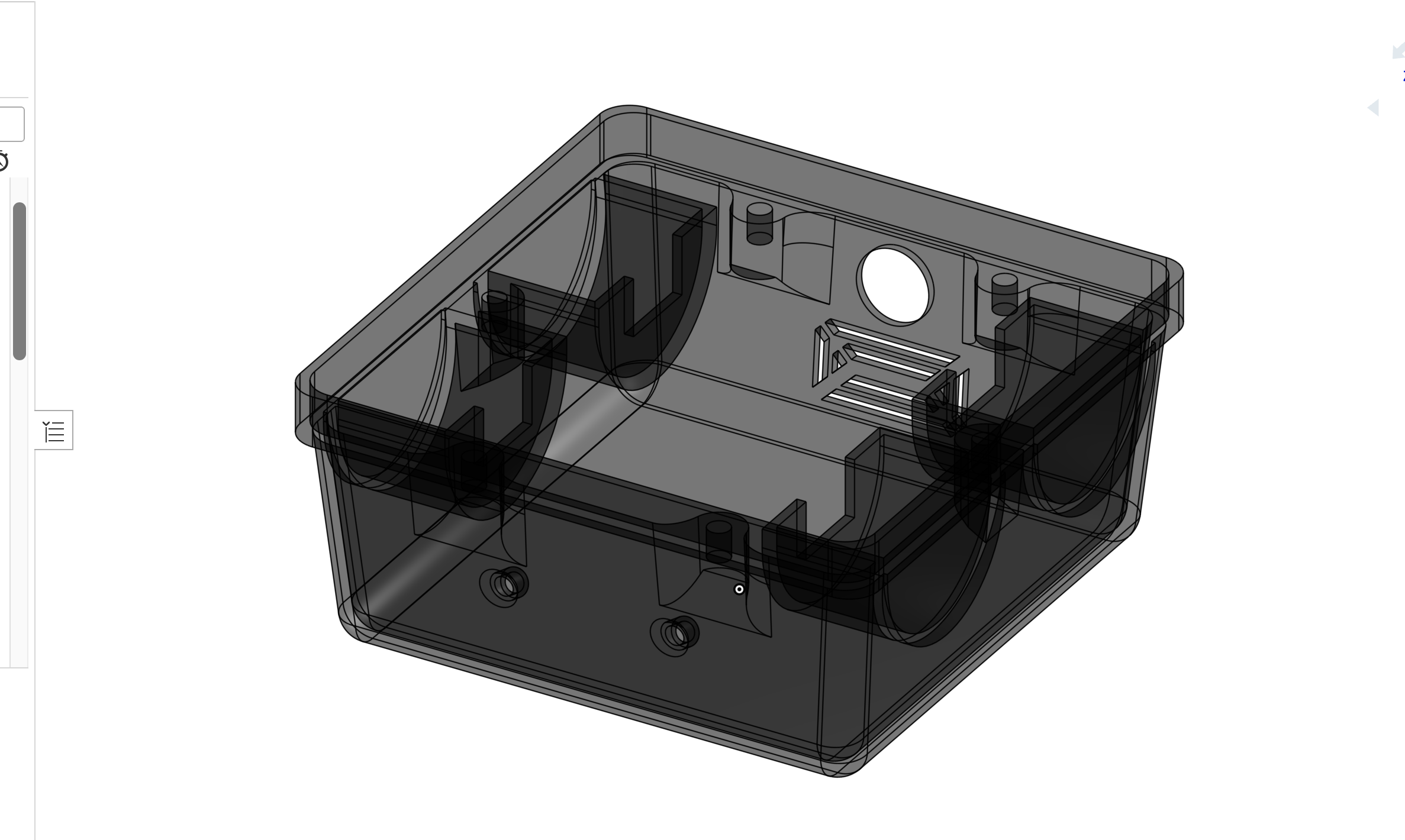
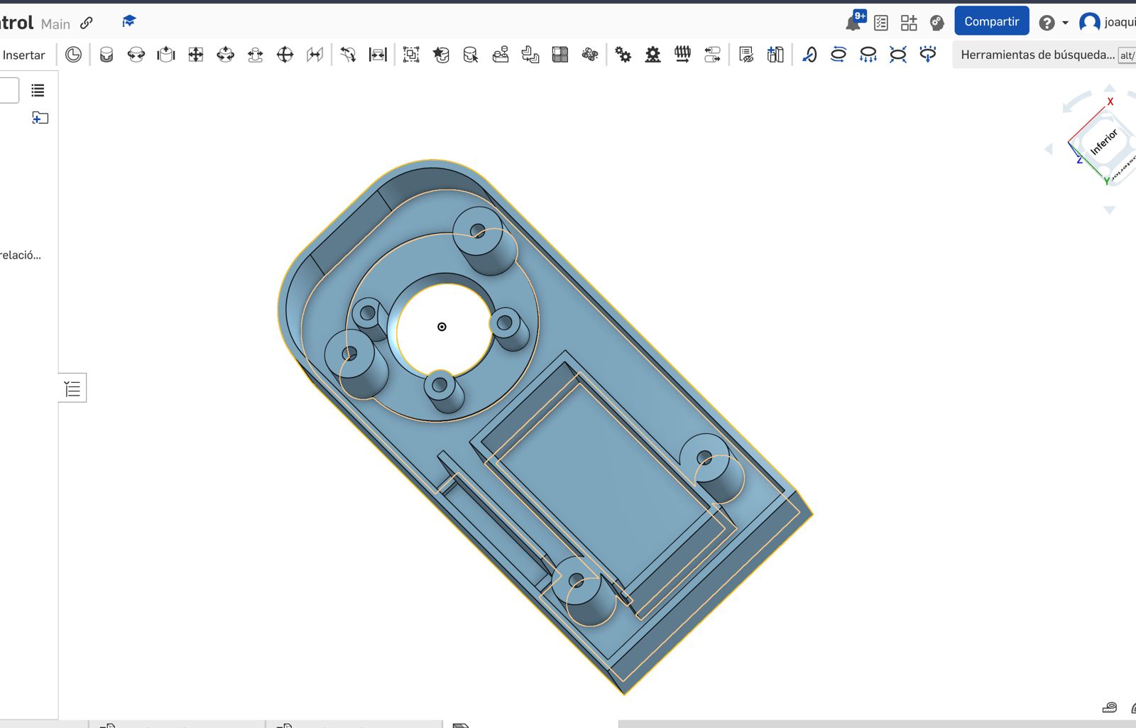
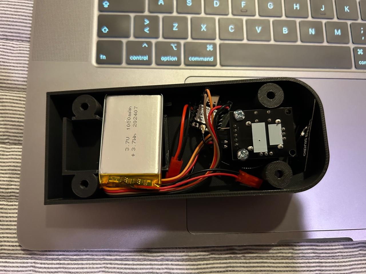
3D Modeling
The design starts very simple, the main plate, the motors and how to lock them in the plate, the wheels, an the case, just to make and idea of how would it be.

This design was very simple, it wasn't contemplating the space for the battery, the place for the board, the button, the leds, almost anything. So, after thinking a bit more.
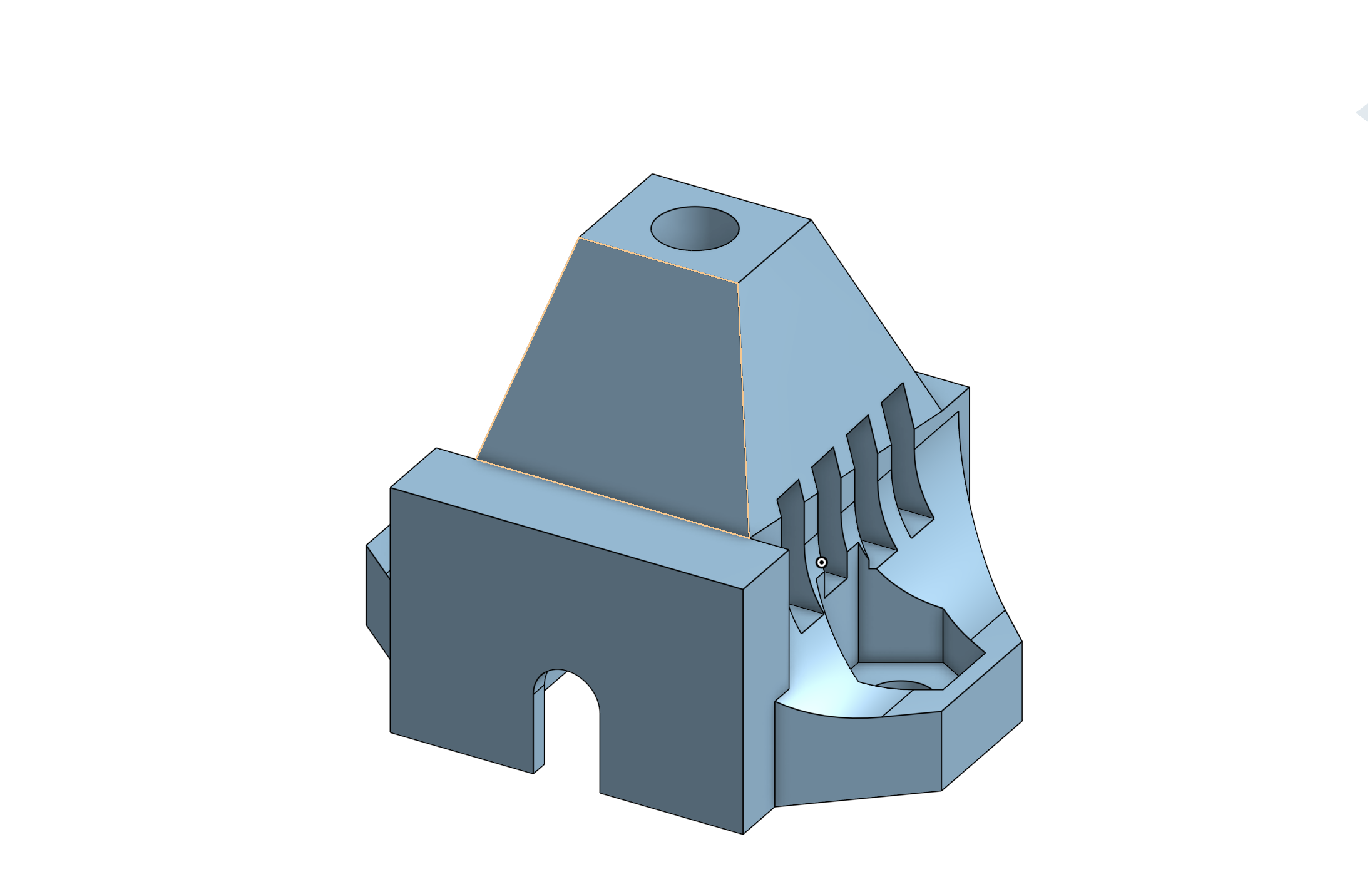
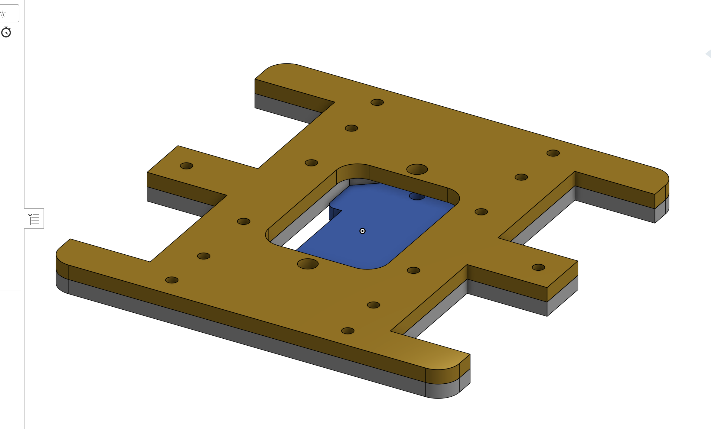
The motor supports
I had to design almost every adapter for the motors. Si this came out:
The case
THe main platform
ACTUALLY, I laser cut this platform and I had to use a new function on the laser cutter. It is basically infill cut. let me show you how does this works:
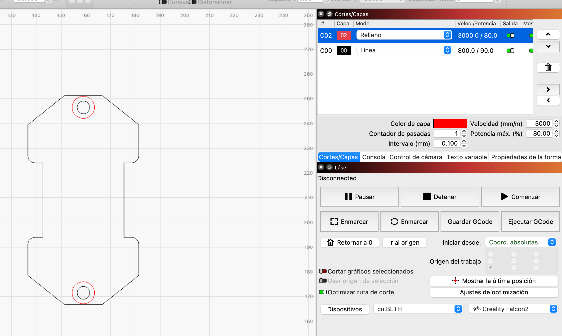
this file has to types of layers, the line (black one) and the infill (the red one) as they name says, the black line will draw just a line, and the red one will fill the figure so it burns all what's inside. Let me show you the preview:
You can go to the week 3 assignment to learn more.
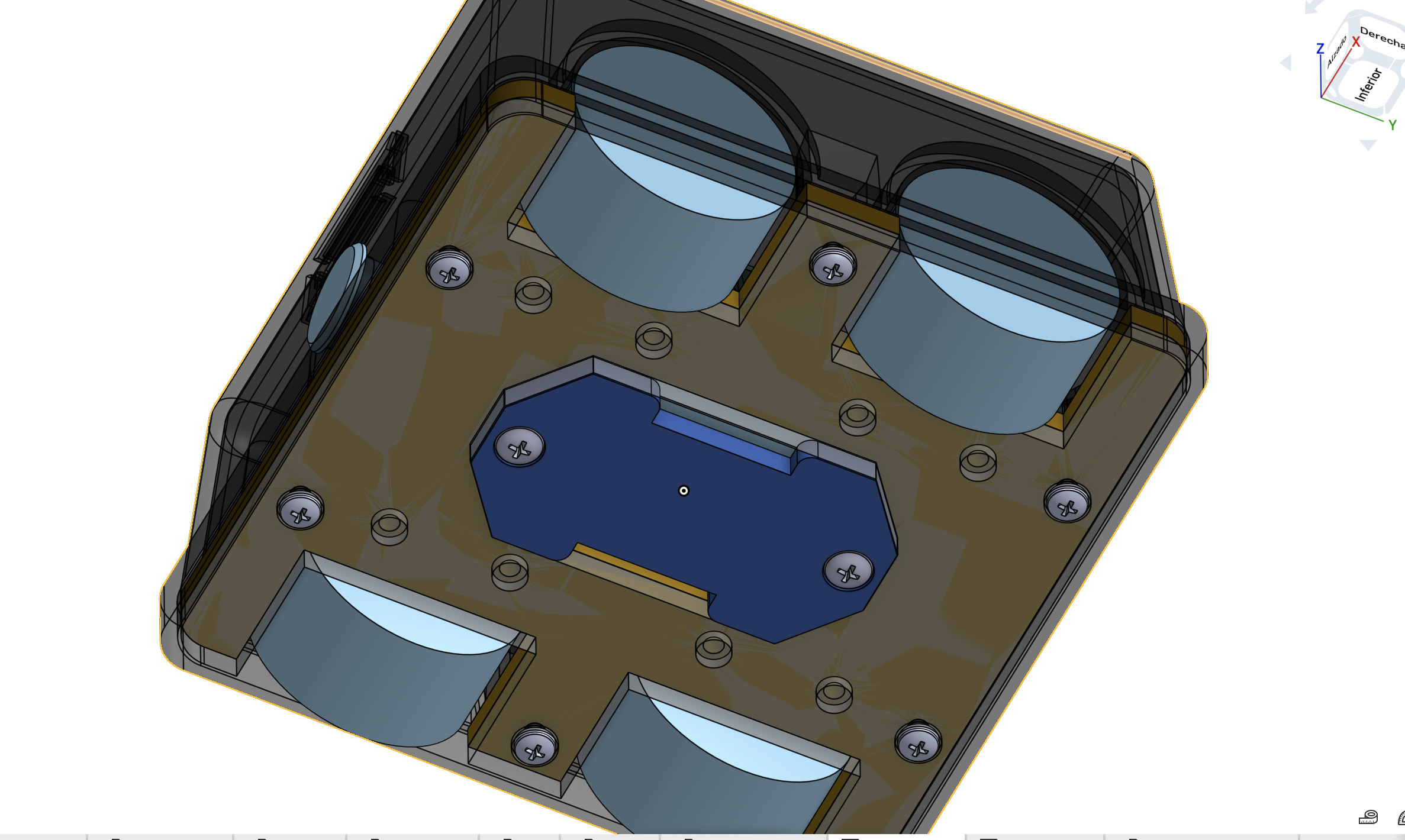
NOTE, the car has 2 support plates the first one is the one that makes the hole work and the second one just hides the motor screws and the cover of the battery space.
and the infill process of the laser cutter is for giving space to the screw heads between both plates. Here are the parameter of that layer:
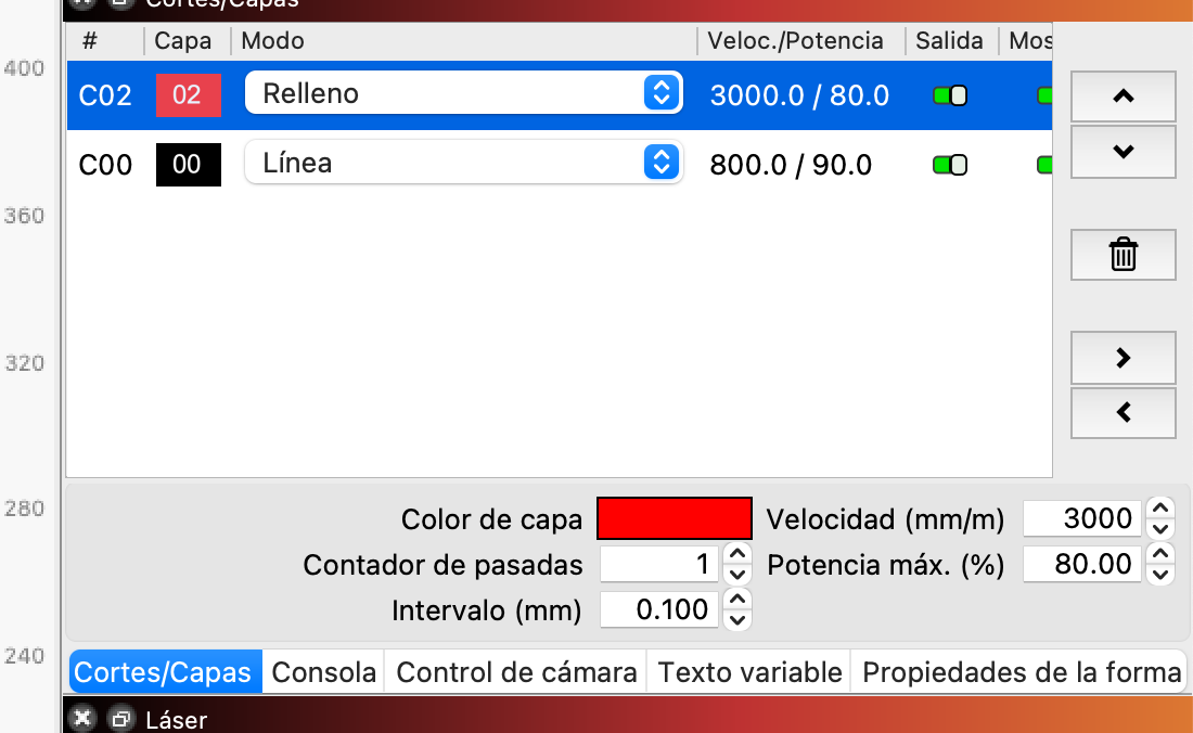
That was enough to burn almost the exact half of the MDF.
The 3D files
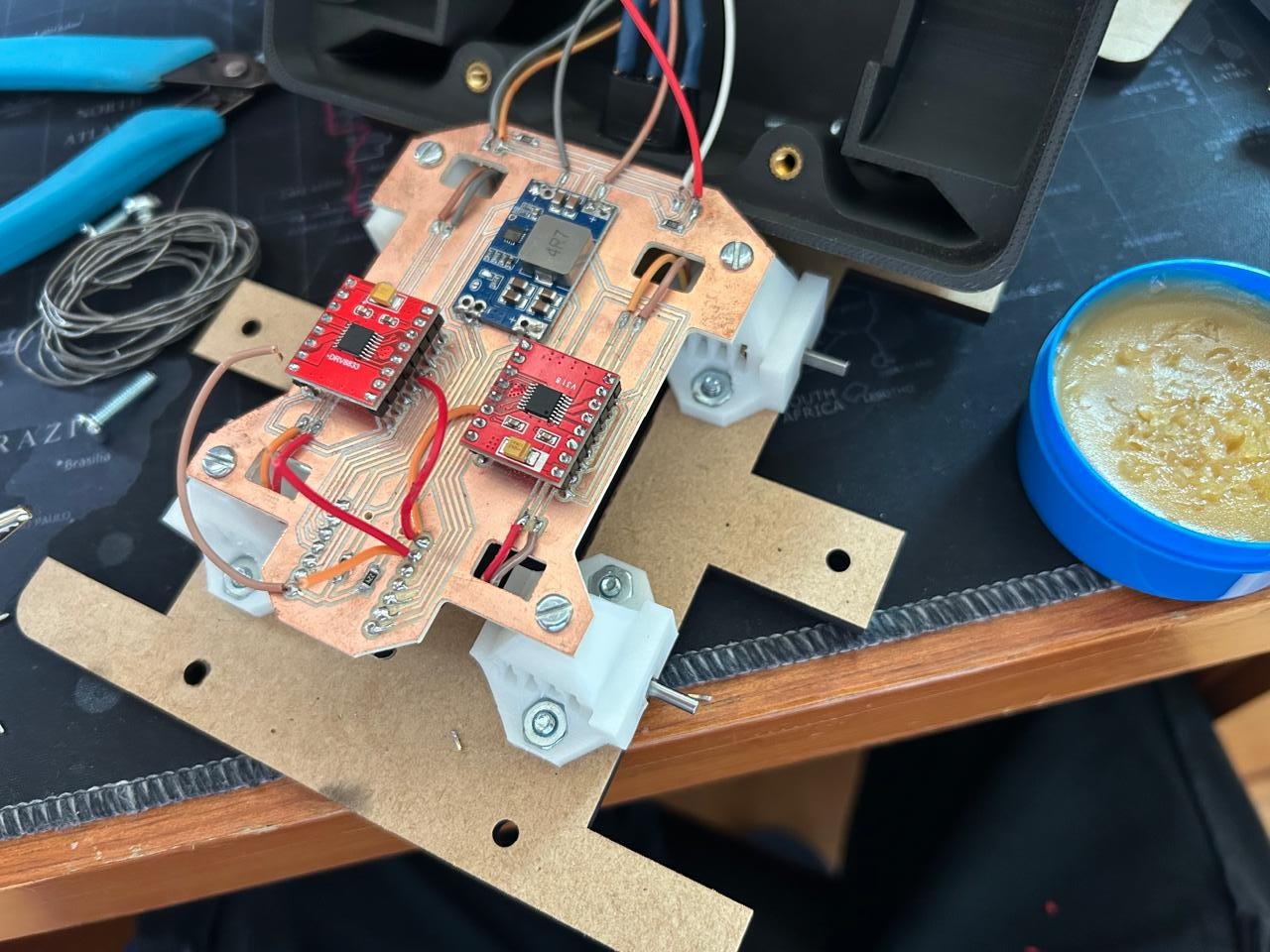
The PCB
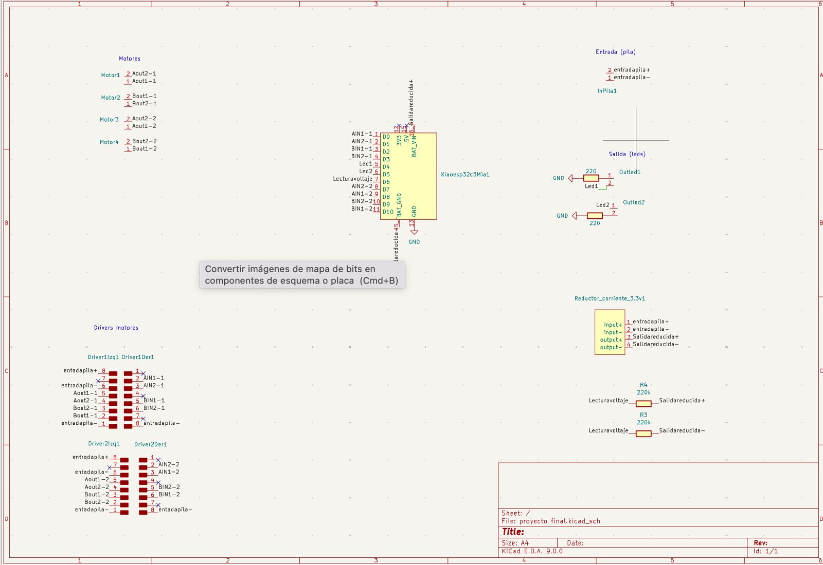
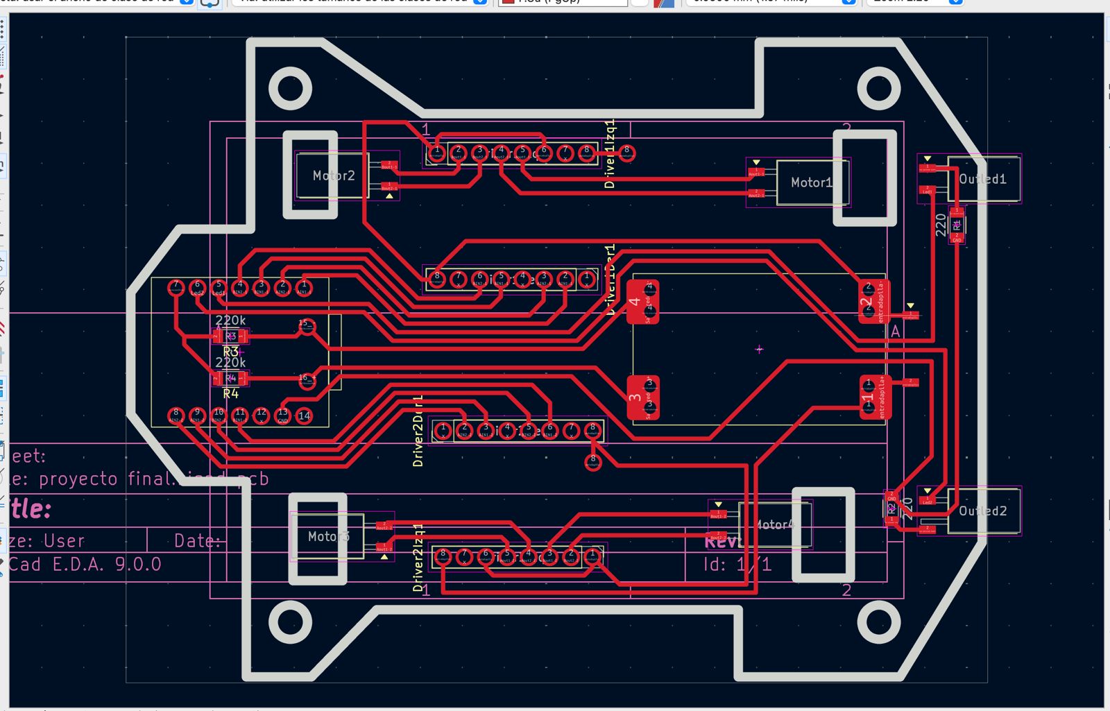
This PCB was really simple, I just needed the micro, the drivers, and the inputs and outputs for the motors leds and batteries. So, using what I learned on the drivers part I made the PCB. I started with my schematic using the libraries fro the fab and included, but once I went to the PCB editor I realized there was going to be a problem.
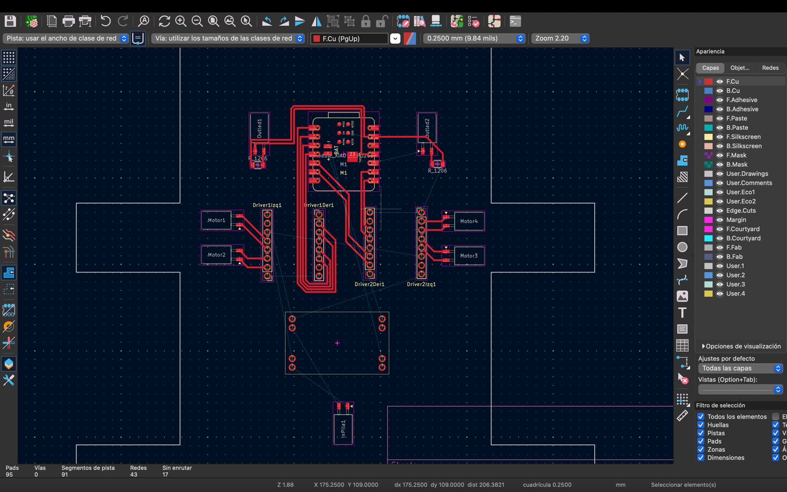
The foot print of the micro controller is contemplating to be completely touching the copper plate, but that's not how I was to place it. I was planing placing it from under and with a space between the micro and the plate. With enough space to place some wires on the battery ports. So I had to create my own footprint and symbol.
I have to say many things about this PCB, I contemplated to do some extra steps with some wires because there was no way to connect all the necessary pins.
There were only 2 wires contemplated, how ever I had o add 4 more to the contemplated, so I ended up with 6 extra wires.
And here is why. When I first connected the circuit to the battery and tried to move the motor, they didn't move at all. It didn't take to long to remember that the stand by Pin has to be connected to the output
voltage of the micro controller, and the grounds also have to be all connected.
Take note of this, if you are trying to connect those pin with a wire ALWAYS disconnect the battery, I didn't disconnected and by accident touched the voltage input from the battery on the micro controller ground
and there went my first micro controller. I burned and I burned my finger.
So, lesson learned.

That's what the lesson learned looks like, no manipulating, just fixed wires so they con NOT move.
That wasn't everything. As I had already soldered the input cables of the battery, I was moving to much the case, and one of the broke, touching a wrong line on the PCB and burning once again the micro controller.
So, ALWAYS disconnect the battery.
Alright two lessons on a short time, this last one is less expensive, When you connect the micro to the PC you are giving it 5V, so the 5V pin is available, BUT, when you connect the battery as it accepts only 3.7V with the battery
pins, the 5V output does not work anymore, so you have to use the 3.3V output.
The PCB files
The PCB
The library of my symbols on kicad
My library.bak
MINI560.kicad_mod
my Xiao.kicad_mod
The bluetooth code
Let's start with the server, the server is basically the micro controller that creates a space where other devices (clients) can connect. This server will define its name, and it "UUID", it's unique identification, it will also declare he services it will have, and the characteristics, this characteristic are what can it do, read, write, notify, all of them, just two or just one.
/*
Based on Neil Kolban example for IDF: https://github.com/nkolban/esp32-snippets/blob/master/cpp_utils/tests/BLE%20Tests/SampleNotify.cpp
Ported to Arduino ESP32 by Evandro Copercini
updated by chegewara and MoThunderz
*/
#include BLEDevice.h>
#include BLEServer.h>
#include BLEUtils.h>
#include BLE2902.h>
#define pinxjoy A0
#define pinyjoy A1
#define pinboton 4


// Initialize all pointers
BLEServer* pServer = NULL;                        // Pointer to the server
BLECharacteristic* pCharacteristic_1 = NULL;      // Pointer to Characteristic 1
BLECharacteristic* pCharacteristic_2 = NULL;   // Pointer to Characteristic 2

BLEDescriptor *pDescr_1;                          // Pointer to Descriptor of Characteristic 1
BLE2902 *pBLE2902_1;                              // Pointer to BLE2902 of Characteristic 1
BLE2902 *pBLE2902_2;                             // Pointer to BLE2902 of Characteristic 2

// Some variables to keep track on device connected
bool deviceConnected = false;
bool oldDeviceConnected = false;

int xjoy = 0;
int yjoy = 0;


// See the following for generating UUIDs:
// https://www.uuidgenerator.net/
// UUIDs used in this example:

#define SERVICE_UUID          "4fafc201-1fb5-459e-8fcc-c5c9c331914b"
#define CHARACTERISTIC_UUID_1 "beb5483e-36e1-4688-b7f5-ea07361b26a8"
#define CHARACTERISTIC_UUID_2 "1c95d5e3-d8f7-413a-bf3d-7a2e5d7be87e"

// Callback function that is called whenever a client is connected or disconnected
class MyServerCallbacks: public BLEServerCallbacks {
    void onConnect(BLEServer* pServer) {
      deviceConnected = true;
    };

    void onDisconnect(BLEServer* pServer) {
      deviceConnected = false;
  };
}

void setup() {
  Serial.begin(115200);

  pinMode(pinxjoy, INPUT);
  pinMode(pinyjoy, INPUT);
  pinMode(pinboton, INPUT_PULLUP);

  delay(1000);

  // Create the BLE Device
  BLEDevice::init("ESP32");

  // Create the BLE Server
  pServer = BLEDevice::createServer();
  pServer->setCallbacks(new MyServerCallbacks());

  // Create the BLE Service
  BLEService *pService = pServer->createService(SERVICE_UUID);

  // Create a BLE Characteristic
  pCharacteristic_1 = pService->createCharacteristic(
                      CHARACTERISTIC_UUID_1,
                      BLECharacteristic::PROPERTY_READ   |
                      BLECharacteristic::PROPERTY_WRITE
                    );
  pCharacteristic_2 = pService->createCharacteristic(
                      CHARACTERISTIC_UUID_2,
                      BLECharacteristic::PROPERTY_READ   |
                      BLECharacteristic::PROPERTY_WRITE  |
                      BLECharacteristic::PROPERTY_NOTIFY
                    );

  // Create a BLE Descriptor
  pDescr_1 = new BLEDescriptor((uint16_t)0x2901);
  pDescr_1->setValue("A very interesting variable");
  pCharacteristic_1->addDescriptor(pDescr_1);

  // Add the BLE2902 Descriptor because we are using "PROPERTY_NOTIFY"
  pBLE2902_1 = new BLE2902();
  pBLE2902_1->setNotifications(true);
  pCharacteristic_1->addDescriptor(pBLE2902_1);

  pBLE2902_2 = new BLE2902();
  pBLE2902_2->setNotifications(true);
  pCharacteristic_2->addDescriptor(pBLE2902_2);

  // Start the service
  pService->start();

  // Start advertising
  BLEAdvertising *pAdvertising = BLEDevice::getAdvertising();
  pAdvertising->addServiceUUID(SERVICE_UUID);
  pAdvertising->setScanResponse(false);
  pAdvertising->setMinPreferred(0x0);  // set value to 0x00 to not advertise this parameter
  BLEDevice::startAdvertising();
  Serial.println("Waiting a client connection to notify...");
}

void loop() {
    // notify changed value
    if (deviceConnected) {
      xjoy = analogRead(pinxjoy);
      yjoy = analogRead(pinyjoy);
      Serial.print("X:");
      Serial.println(xjoy);
      Serial.print("Y:");
      Serial.println(yjoy);
      String dir = "";

      if (xjoy > 4000){
        dir = "F";
        pCharacteristic_2->setValue(dir.c_str());
      }
      if (xjoy <= 800){
        dir = "B";
        pCharacteristic_2->setValue(dir.c_str());
        }
      if (yjoy == 4095 && xjoy < 3690 && xjoy > 3000){
        dir = "D";
        pCharacteristic_2->setValue(dir.c_str());
      }
      if (yjoy < 1500 && xjoy < 3900){
          dir = "I";
          pCharacteristic_2->setValue(dir.c_str());
        }
      if (yjoy == 4095 && xjoy == 4095){
        dir = "RD";
        pCharacteristic_2->setValue(dir.c_str());
      }
      if (yjoy < 20 && xjoy == 4095){
          dir = "RI";
          pCharacteristic_2->setValue(dir.c_str());
        }
      if (yjoy > 3400 && yjoy < 3600 && xjoy > 3400 && xjoy < 3600){
        dir = "S";
        pCharacteristic_2->setValue(dir.c_str());
        Serial.println("Esta");
        }

      delay(50);
    }
    // The code below keeps the connection status uptodate:
    // Disconnecting
    if (!deviceConnected && oldDeviceConnected) {
        delay(500); // give the bluetooth stack the chance to get things ready
        pServer->startAdvertising(); // restart advertising
        Serial.println("start advertising");
        oldDeviceConnected = deviceConnected;
    }
    // Connecting
    if (deviceConnected && !oldDeviceConnected) {
        // do stuff here on connecting
        oldDeviceConnected = deviceConnected;
    }
}
Let's go real quick trough this
#include <)BLEDevice.h>
#include <)BLEServer.h>
#include <)BLEUtils.h>
#include <)BLE2902.h>
#define pinxjoy A0
#define pinyjoy A1
#define pinboton 4
Bring the necessary libraries and define the pins
// Initialize all pointers
BLEServer* pServer = NULL;                        // Pointer to the server
BLECharacteristic* pCharacteristic_1 = NULL;      // Pointer to Characteristic 1

BLEDescriptor *pDescr_1;                          // Pointer to Descriptor of Characteristic 1
BLE2902 *pBLE2902_1;                              // Pointer to BLE2902 of Characteristic 1
BLE2902 *pBLE2902_2;                             // Pointer to BLE2902 of Characteristic 2
Kind of creates a relation between BLE parameters and our variables that we will be using in our code.
// Some variables to keep track on device connected
bool deviceConnected = false;
bool oldDeviceConnected = false;

int xjoy = 0;
int yjoy = 0;
Creates the variables to let the system know if it is connected or if an old device is connected. Also defines the joystick in ceros.
#define SERVICE_UUID          "4fafc201-1fb5-459e-8fcc-c5c9c331914b"
#define CHARACTERISTIC_UUID_1 "beb5483e-36e1-4688-b7f5-ea07361b26a8"
#define CHARACTERISTIC_UUID_2 "1c95d5e3-d8f7-413a-bf3d-7a2e5d7be87e"
Defines the UUID of the service and the characteristics. Each one has to have a different one. Those are UNIQUE
              // Callback function that is called whenever a client is connected or disconnected
class MyServerCallbacks: public BLEServerCallbacks {
    void onConnect(BLEServer* pServer) {
      deviceConnected = true;
    };

    void onDisconnect(BLEServer* pServer) {
      deviceConnected = false;
    };
}
As the explanation says it defines if a client is connected or not.
  pCharacteristic_1 = pService->createCharacteristic(
                      CHARACTERISTIC_UUID_1,
                      BLECharacteristic::PROPERTY_READ   |
                      BLECharacteristic::PROPERTY_WRITE
                    );

  pCharacteristic_2 = pService->createCharacteristic(
                      CHARACTERISTIC_UUID_2,
                      BLECharacteristic::PROPERTY_READ   |
                      BLECharacteristic::PROPERTY_WRITE  |
                      BLECharacteristic::PROPERTY_NOTIFY
                    );
Here we are creating the characteristics, and telling the program what can they do, you have to assign a different UUID for each characteristic. And you can write just one or the 3 of them.
  pDescr_1 = new BLEDescriptor((uint16_t)0x2901);
  pDescr_1->setValue("A very interesting variable");
  pCharacteristic_1->addDescriptor(pDescr_1);
The descriptor, they are just to let the client know want can each characteristic do.
  BLEAdvertising *pAdvertising = BLEDevice::getAdvertising();
  pAdvertising->addServiceUUID(SERVICE_UUID);
  pAdvertising->setScanResponse(false);
  pAdvertising->setMinPreferred(0x0);  // set value to 0x00 to not advertise this parameter
  BLEDevice::startAdvertising();
  Serial.println("Waiting a client connection to notify...");
Starts the advertising with the service UUID and waits for responses.
pCharacteristic_2->setValue(dir.c_str());
This is the line that writes the value on the characteristic so the client can read it. It sends the data.
The client code
/**
 * A BLE client example that is rich in capabilities.
 * There is a lot new capabilities implemented.
 * author unknown
 * updated by chegewara and MoThunderz
 */

#include "BLEDevice.h"
//#include "BLEScan.h"

//motor 1
#define motorDB 2
#define motorDB2 3

//motor 2
#define motorDA 5
#define motorDA2 4
//mototr 3
#define motorIA 19
#define motorIA2 17

//motor 4
#define motorIB 18
#define motorIB2 20

#define LED1 6
#define LED2 7

// Define UUIDs:
static BLEUUID serviceUUID("4fafc201-1fb5-459e-8fcc-c5c9c331914b");
static BLEUUID    charUUID_1("beb5483e-36e1-4688-b7f5-ea07361b26a8");
static BLEUUID    charUUID_2("1c95d5e3-d8f7-413a-bf3d-7a2e5d7be87e");

// Some variables to keep track on device connected
static boolean doConnect = false;
static boolean connected = false;
static boolean doScan = false;

// Define pointer for the BLE connection
static BLEAdvertisedDevice* myDevice;
BLERemoteCharacteristic* pRemoteChar_1;
BLERemoteCharacteristic* pRemoteChar_2;

// Callback function for Notify function
static void notifyCallback(BLERemoteCharacteristic* pBLERemoteCharacteristic,
                            uint8_t* pData,
                            size_t length,
                            bool isNotify) {
  if(pBLERemoteCharacteristic->getUUID().toString() == charUUID_1.toString()) {

    // convert received bytes to integer
    uint32_t counter = pData[0];
    for(int i = 1; i length; i++) {
      counter = counter | (pData[i] << i*8);
    }

    // print to Serial
    Serial.print("Characteristic 1 (Notify) from server: ");
    Serial.println(counter );
  }
}

// Callback function that is called whenever a client is connected or disconnected
class MyClientCallback : public BLEClientCallbacks {
  void onConnect(BLEClient* pclient) {
  }

  void onDisconnect(BLEClient* pclient) {
    connected = false;
    Serial.println("onDisconnect");
  }
};

// Function that is run whenever the server is connected
bool connectToServer() {
  Serial.print("Forming a connection to ");
  Serial.println(myDevice->getAddress().toString().c_str());

  BLEClient*  pClient  = BLEDevice::createClient();
  Serial.println(" - Created client");

  pClient->setClientCallbacks(new MyClientCallback());

  // Connect to the remove BLE Server.
  pClient->connect(myDevice);  // if you pass BLEAdvertisedDevice instead of address, it will be recognized type of peer device address (public or private)
  Serial.println(" - Connected to server");

  // Obtain a reference to the service we are after in the remote BLE server.
  BLERemoteService* pRemoteService = pClient->getService(serviceUUID);
  if (pRemoteService == nullptr) {
    Serial.print("Failed to find our service UUID: ");
    Serial.println(serviceUUID.toString().c_str());
    pClient->disconnect();
    return false;
  }
  Serial.println(" - Found our service");

  connected = true;
  pRemoteChar_1 = pRemoteService->getCharacteristic(charUUID_1);
  pRemoteChar_2 = pRemoteService->getCharacteristic(charUUID_2);
  if(connectCharacteristic(pRemoteService, pRemoteChar_1) == false)
    connected = false;
  else if(connectCharacteristic(pRemoteService, pRemoteChar_2) == false)
    connected = false;

  if(connected == false) {
    pClient-> disconnect();
    Serial.println("At least one characteristic UUID not found");
    return false;
  }
  return true;
}

// Function to chech Characteristic
bool connectCharacteristic(BLERemoteService* pRemoteService, BLERemoteCharacteristic* l_BLERemoteChar) {
  // Obtain a reference to the characteristic in the service of the remote BLE server.
  if (l_BLERemoteChar == nullptr) {
    Serial.print("Failed to find one of the characteristics");
    Serial.print(l_BLERemoteChar->getUUID().toString().c_str());
    return false;
  }
  Serial.println(" - Found characteristic: " + String(l_BLERemoteChar->getUUID().toString().c_str()));

  if(l_BLERemoteChar->canNotify())
    l_BLERemoteChar->registerForNotify(notifyCallback);

  return true;
}

// Scan for BLE servers and find the first one that advertises the service we are looking for.
class MyAdvertisedDeviceCallbacks: public BLEAdvertisedDeviceCallbacks {
  //Called for each advertising BLE server.
  void onResult(BLEAdvertisedDevice advertisedDevice) {
    Serial.print("BLE Advertised Device found: ");
    Serial.println(advertisedDevice.toString().c_str());

    // We have found a device, let us now see if it contains the service we are looking for.
    if (advertisedDevice.haveServiceUUID() && advertisedDevice.isAdvertisingService(serviceUUID)) {

      BLEDevice::getScan()->stop();
      myDevice = new BLEAdvertisedDevice(advertisedDevice);
      doConnect = true;
      doScan = true;

    } // Found our server
  } // onResult
}; // MyAdvertisedDeviceCallbacks

void setup() {
  Serial.begin(115200);
  Serial.println("Starting Arduino BLE Client application...");
  BLEDevice::init("");

  pinMode(motorIA, OUTPUT);
  pinMode(motorIA2, OUTPUT);
  pinMode(motorIB, OUTPUT);
  pinMode(motorIB2, OUTPUT);
  pinMode(motorDA, OUTPUT);
  pinMode(motorDA2, OUTPUT);
  pinMode(motorDB, OUTPUT);
  pinMode(motorDB2, OUTPUT);
  pinMode(LED1, OUTPUT);
  pinMode(LED2, OUTPUT);

  digitalWrite(LED1, HIGH);
  digitalWrite(LED2, HIGH);

  // Retrieve a Scanner and set the callback we want to use to be informed when we
  // have detected a new device.  Specify that we want active scanning and start the
  // scan to run for 5 seconds.
  BLEScan* pBLEScan = BLEDevice::getScan();
  pBLEScan->setAdvertisedDeviceCallbacks(new MyAdvertisedDeviceCallbacks());
  pBLEScan->setInterval(1349);
  pBLEScan->setWindow(449);
  pBLEScan->setActiveScan(true);
  pBLEScan->start(5, false);
} // End of setup.

void loop() {

  // If the flag "doConnect" is true then we have scanned for and found the desired
  // BLE Server with which we wish to connect.  Now we connect to it.  Once we are
  // connected we set the connected flag to be true.
  if (doConnect == true) {
    if (connectToServer()) {
      Serial.println("We are now connected to the BLE Server.");
    } else {
      Serial.println("We have failed to connect to the server; there is nothin more we will do.");
    }
    doConnect = false;
  }

  // If we are connected to a peer BLE Server, update the characteristic each time we are reached
  // with the current time since boot.
  if (connected) {
    String rxValue = pRemoteChar_2->readValue();
    if (rxValue == "S"){
      Serial.println("Estatico");
      analogWrite(motorDB, 0);
      analogWrite(motorDA, 0);
      analogWrite(motorIB, 0);
      analogWrite(motorIA, 0);
      analogWrite(motorDB2, 0);
      analogWrite(motorDA2, 0);
      analogWrite(motorIB2, 0);
      analogWrite(motorIA2, 0);
    }
    if (rxValue == "F"){
      Serial.println("Frente");
      analogWrite(motorDB2, 100);
      analogWrite(motorDA2, 100);
      analogWrite(motorIB2, 100);
      analogWrite(motorIA2, 100);
    }
    if (rxValue == "B"){
      Serial.println("Atras");
      analogWrite(motorDB, 100);
      analogWrite(motorDA, 100);
      analogWrite(motorIB, 100);
      analogWrite(motorIA, 100);
    }
    if (rxValue == "D"){
      Serial.println("Derecha");
      analogWrite(motorDB, 100);
      analogWrite(motorDA2, 100);
      analogWrite(motorIB2, 100);
      analogWrite(motorIA, 100);
    }
    if (rxValue == "I"){
      Serial.println("Izquierda");
      analogWrite(motorDB2, 100);
      analogWrite(motorDA, 100);
      analogWrite(motorIB, 100);
      analogWrite(motorIA2, 100);
    }
    if (rxValue == "RD"){
      Serial.println("Rotar derecha");
      analogWrite(motorDB, 100);
      analogWrite(motorDA, 100);
      analogWrite(motorIB2, 100);
      analogWrite(motorIA2, 100);
    }
    if (rxValue == "RI"){
      Serial.println("Rotar izquierda");
      analogWrite(motorDB2, 100);
      analogWrite(motorDA2, 100);
      analogWrite(motorIB, 100);
      analogWrite(motorIA, 100);
    }


  }else if(doScan){
    BLEDevice::getScan()->start(0);  // this is just example to start scan after disconnect, most likely there is better way to do it in arduino
  }

  // In this example "delay" is used to delay with one second. This is of course a very basic
  // implementation to keep things simple. I recommend to use millis() for any production code
  delay(50);
}
What's new?
// Define UUIDs:
static BLEUUID serviceUUID("4fafc201-1fb5-459e-8fcc-c5c9c331914b");
static BLEUUID    charUUID_1("beb5483e-36e1-4688-b7f5-ea07361b26a8");
static BLEUUID    charUUID_2("1c95d5e3-d8f7-413a-bf3d-7a2e5d7be87e");
On the client code we have to define the same UUID's for the same serice and characteristics, the device will look exactl for this numers
// Define pointer for the BLE connection
static BLEAdvertisedDevice* myDevice;
BLERemoteCharacteristic* pRemoteChar_1;
BLERemoteCharacteristic* pRemoteChar_2;
Tells the program we will use the number of the characteristics to call a predefined BLE code
// Callback function for Notify function
static void notifyCallback(BLERemoteCharacteristic* pBLERemoteCharacteristic,
                            uint8_t* pData,
                            size_t length,
                            bool isNotify) {
  if(pBLERemoteCharacteristic->getUUID().toString() == charUUID_1.toString()) {

    // convert received bytes to integer
    uint32_t counter = pData[0];
    for(int i = 1; i length; i++) {
      counter = counter | (pData[i] << i*8);
    }
  }
}

    // print to Serial
    Serial.print("Characteristic 1 (Notify) from server: ");
    Serial.println(counter );
Reads and rewrites the content of the descriptors.
  class MyClientCallback : public BLEClientCallbacks {
  void onConnect(BLEClient* pclient) {
  }

  void onDisconnect(BLEClient* pclient) {
    connected = false;
    Serial.println("onDisconnect");
  }
};
Notifys if is succesfully conected to the server or not.
  bool connectToServer() {
  Serial.print("Forming a connection to ");
  Serial.println(myDevice->getAddress().toString().c_str());
  }
Tells you who are you connecting to.
  BLEClient*  pClient  = BLEDevice::createClient();
  Serial.println(" - Created client");
Creates de client.
  BLERemoteService* pRemoteService = pClient->getService(serviceUUID);
  if (pRemoteService == nullptr) {
    Serial.print("Failed to find our service UUID: ");
    Serial.println(serviceUUID.toString().c_str());
    pClient->disconnect();
    return false;
  }
  Serial.println(" - Found our service");
Check if we found the sevice we are looking for.
  connected = true;
  pRemoteChar_1 = pRemoteService->getCharacteristic(charUUID_1);
  pRemoteChar_2 = pRemoteService->getCharacteristic(charUUID_2);
  if(connectCharacteristic(pRemoteService, pRemoteChar_1) == false)
    connected = false;
  else if(connectCharacteristic(pRemoteService, pRemoteChar_2) == false)
    connected = false;

  if(connected == false) {
    pClient-> disconnect();
    Serial.println("At least one characteristic UUID not found");
    return false;
  }
Double checks if the service we connected with has the charactersitics we are looking for.
  bool connectCharacteristic(BLERemoteService* pRemoteService, BLERemoteCharacteristic* l_BLERemoteChar) {
  // Obtain a reference to the characteristic in the service of the remote BLE server.
  if (l_BLERemoteChar == nullptr) {
    Serial.print("Failed to find one of the characteristics");
    Serial.print(l_BLERemoteChar->getUUID().toString().c_str());
    return false;
  }
  Serial.println(" - Found characteristic: " + String(l_BLERemoteChar->getUUID().toString().c_str()));

  if(l_BLERemoteChar->canNotify())
    l_BLERemoteChar->registerForNotify(notifyCallback);

  return true;
}
Checks that the UUID's of the characteristics are the same.
class MyAdvertisedDeviceCallbacks: public BLEAdvertisedDeviceCallbacks {
  //Called for each advertising BLE server.
  void onResult(BLEAdvertisedDevice advertisedDevice) {
    Serial.print("BLE Advertised Device found: ");
    Serial.println(advertisedDevice.toString().c_str());

    // We have found a device, let us now see if it contains the service we are looking for.
    if (advertisedDevice.haveServiceUUID() && advertisedDevice.isAdvertisingService(serviceUUID)) {

      BLEDevice::getScan()->stop();
      myDevice = new BLEAdvertisedDevice(advertisedDevice);
      doConnect = true;
      doScan = true;
    }
  }
}
Tells you ir found something, and if everythong is ok with the UUID's ti will connect.
The code files
NOTE, important to mention that the server code goes to the controller micro and the clients goes to the car micro.
The process
But first
testing the driver
Making the PCB
A fail while printing the case
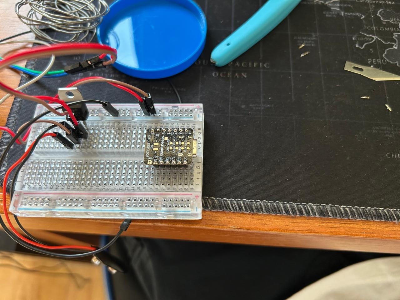
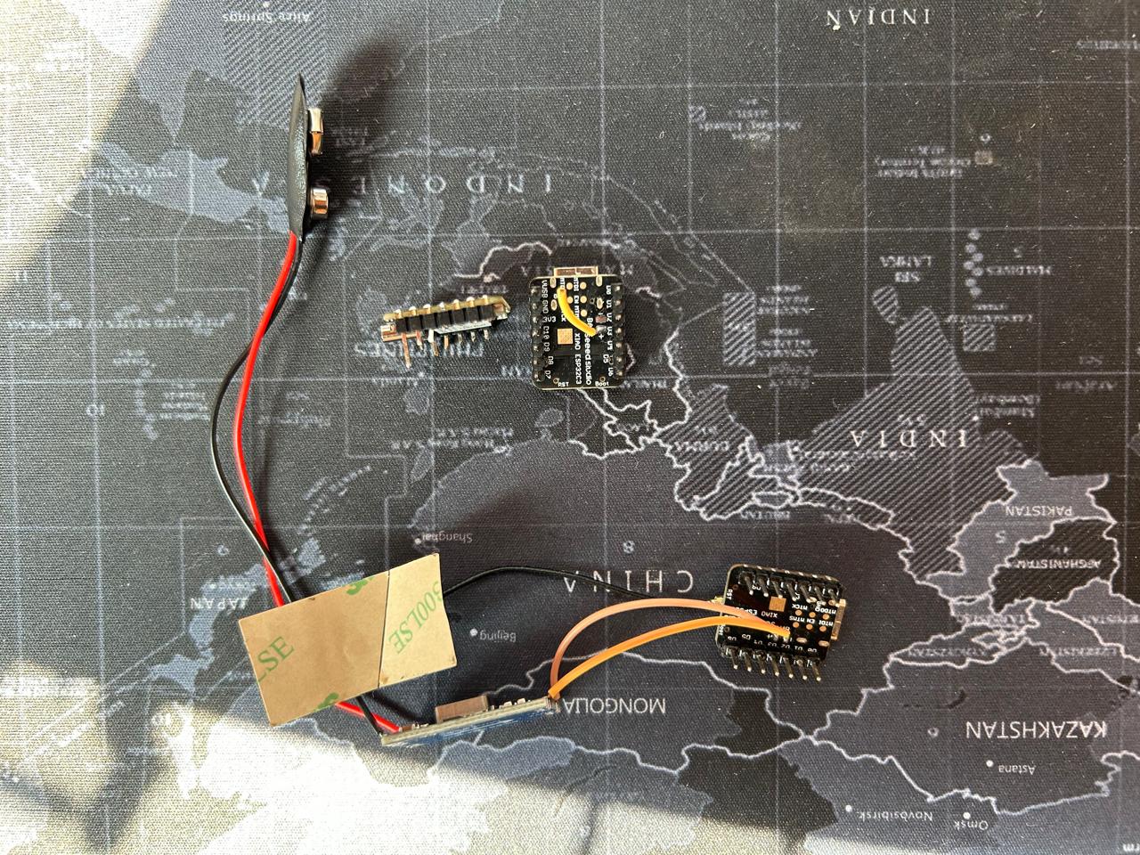
I found a easier way to solder the micro controller pins with a protoboard
The installed plate
The liscene I choose
I choose a creative commons atributtion liscence and here it is:
The Flea © 2025 by Joaquin Gómez V. is licensed under CC BY 4.0Issues
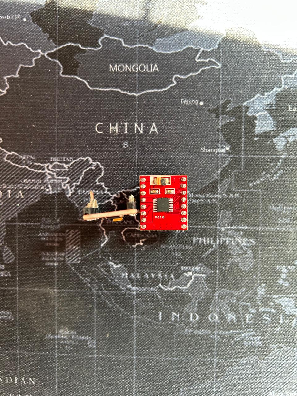
I had to improvise a controller on the last days
The first idea was to make the controller with 9V battery and a voltage reducer. But the XIAO doesn't allows that kif of batteries,
So, my 3th burned micro controller. Aaaaand I had to go get a Lithio battery for it to work without a computer. But that was greate because it made a los easier the circuit. It only has 3 components, the joystick, the micro controller and the battery.
And this works, Amazing.
The files
MORE issues
I burned 2 drivers, never connect the oppsite termials, they explode. And 3 micros.
Learining outcome
Doing this kind of stuff seems like something easy or quick, but it is not, there are many many MANY things to take into account, there is always that goes wrong on the last moment,
you have to be very carefull when dealing with the components, and planing how your are going to do it. Other ways a desing error might be the end.
That's why I choose easy to modify dsign.
In my case I didn't decided what to so until I had a few weeks left, so my first ideas dissapeared, as the time passed I had to think about a easier proyect each day.
That's why I endedcup with a car. How ever I still feel very proud of what I made because I made it almost from cero. The things I definitely didn't know how to do it I had lo look a tutorial for it
understand the most I could and aplly it. This is a very great challenge. I liked it.