Week 3. Computer controlled cutting
Hello again future me or new fabacademy student, here we are on a new week with more doubts than answers but here I will try to answer some of them of the new topis of week 3. The topic is computer controlled cutting (laser cutting/engraving).
But first
Here is the group assignment of my fablab team.
What is computer controlled cutting?
Is basically doing it literally, there are machines with many different methods of cutting different types of materials, there are machines with knives, saws, drillers and laser, this time we will be learning about the laser cutting machines. As the name says it this kind of machines use powerful light to cut trough different materials and engraving some others. The most common machines are the C02 laser and the diode laser, each one works as its names says. But there are many differences between them, starting with physical appearance.
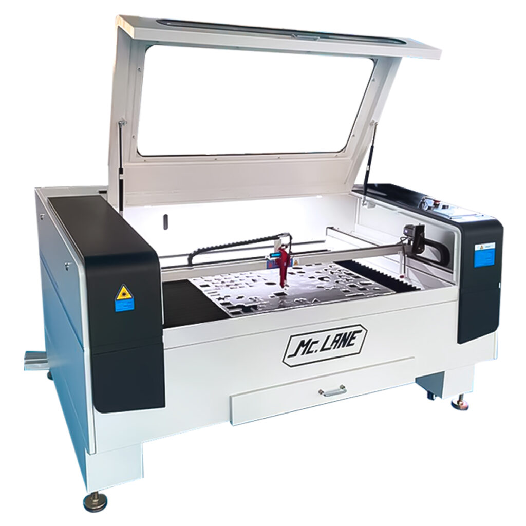
This is how a CO2 laser cutter looks like.
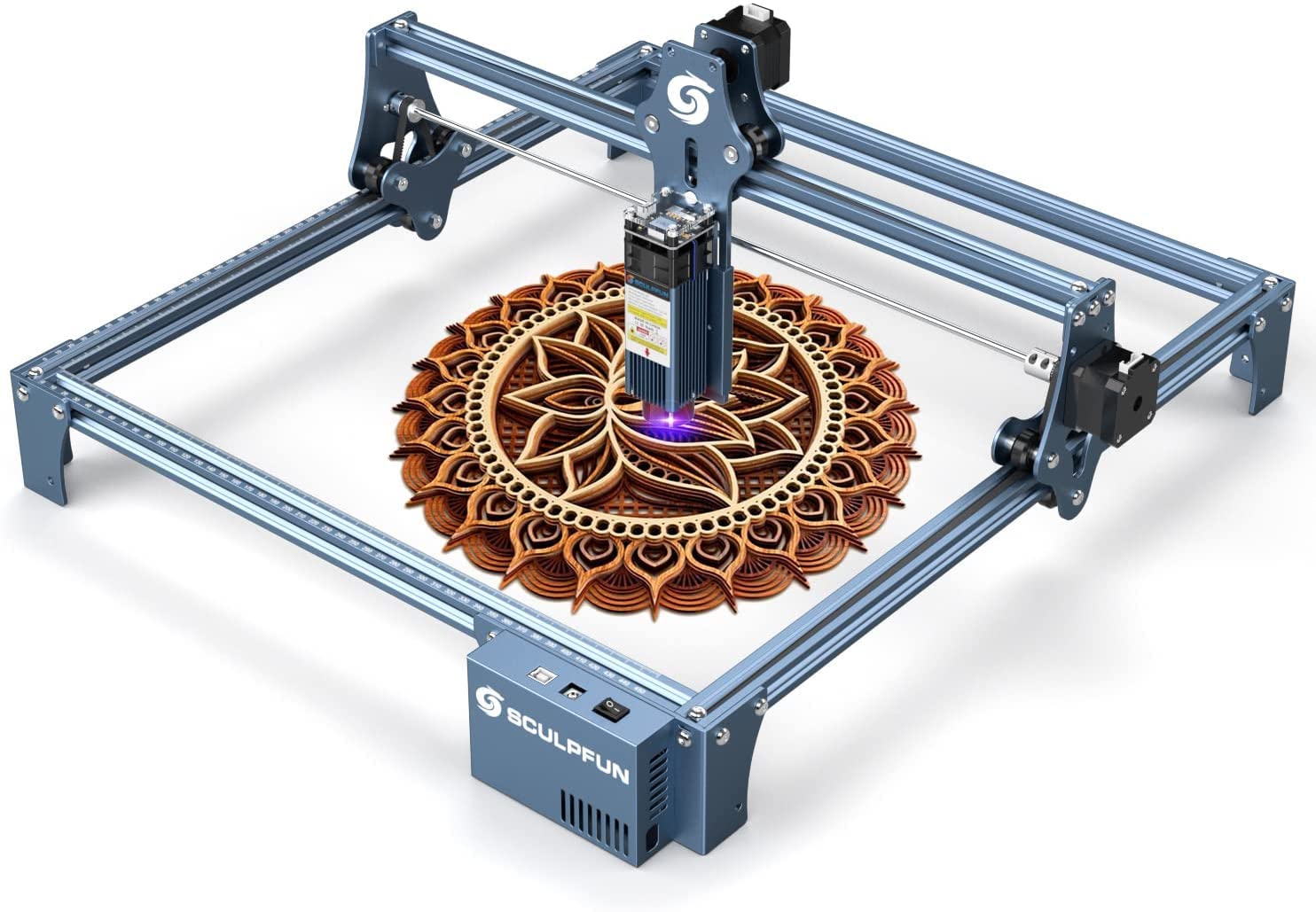
And this is how a diode laser cutter looks like.
About safety
First is first
Safety there are a few things to take into account when cutting with laser:
- There is always a fire risk, DON'T leave the machine by its own, ALWAYS be there while it's working. Remember the closest fire extinguisher so you can act if needed.
- DO NOT look straight to the laser, it is very powerful and it can produce eye damage.
- Do no try to touch anything moving while its working.
- While working always keep the laser casing close.
- Try to not breath the residual smoke.
-
Special consideration for the CO2 laser. On the CO2 laser, the laser comes form the back of the machine,
and with some mirrors it directs the light ot the head. This mirror are place on the side of the
machine and on the head, so the X support of the head is also dangerous. Here a video:
The head is on the very left, the wood is being placed between the head and the side of the cutting zone.
Do NOT use this materials
- PVC (Poly vinyl Chloride (emits chlorine gas))
- Vinyl (emits chlorine gas)
- Pleather (emits chlorine gas)
- Artificial leather (emits chlorine gas)
- polycarbonate (catches fire)
- lexan (catches fire)
- ABS (melts/cyanide)
- HDPE/Milk plastic box (Catcher fire)
- Polystyrene foam (catches fire)
- Expoxy (Burns/smoke)
- Fiber glass and coated fiber carbon (toxic smoke)
- Any food
The good news
Taking into acount the safety recommendations its for the what can we cut/engrave and how. Here is a list of material we can cut:
- Paper
- Cardboard
- Foaming
- Felt (fieltro)
- Cotton and mixed fiber fabrics
- Thick synthetic fiber fabrics
- Synthetic lycra and thin
- Natural leather
- Synthetic leather
- Rubber/latex
- Cork
- MDF
- Wood
- Plywood
- Plastic
- Acrylic (if it is a transparent color ot has to have a black recover)
- Glass and crystals (it has to have a black recover so it doesn't damage the diode)
- Ceramic (black cover)
- Marble/onyx among other stones
- Tile
- Metal
NOTE, from glass and crystals the lasers are just capable of engraving, not cutting
NOTE, information recovered form this website.
How to operate a CO2 laser cutter?
Turning it up
The one on the Fablab Puebla has 4 main switches to turn it on. The first one is a simple multicontact in the back side of the machine, this will turn on the air extractor, and give energy to the machine. Then insert the key where it should be and turn it, then turn on the switches on the side of the machine, and last release the big red button in front of you, then the machine is turned on.
The program
Now, to prepare the document we need 2 things, the DXF file ( Here is a DXF example file ) of our design and a program called, "smart carve". This program allows you to import you file, edit it set the parameters, like: laser power, speed, number of passes,
if you want just a cut or engrave, or infill, it allows you to create arrays in case you need many of the same piece, and many other things.
NOTE, in order to use this program you a need a license, but this license is a red USB that you need to connect to the computer and work with the USB connected, once you take out the USB the program will close.
In this kind of programs the color on the right side up are very important because those colors will tell the machine what to do (cut, engrave or infill) if you need to cut a piece with some infill, you will need to place the cut lines on a color and set the parameters to cut, fo the infill engrave, you will need to put the figure to engrave on a different color and set different parameters. Once you end setting the instructions you will have to save the file in a USB and name it to connect it to the machine. Here is a laser cutter file
The machine
Importing the file
With the file on the USB we have to connect it to it's input port and download it to the laser memory, for this we will use the user panel and the navigate buttons. Click on "file", go to the "udisk" option and "read the u disk", this will go o the connected USB and read all the compatible files in it and display on the screen. Select the desire file with "enter" and click on "copy to ram" this will take the file from the USB to the memory of the machine. Now click "scape" until the main menu, where you will find you file, select it with "enter" and its ready to frame and start.
Setting origin
Now, before getting started with the cut we have to place head on the needed position. This means, our material usually doesn't take the hole bed of the machine, it has some margins on the sides. That's what we need to place the head. So, place the material and in the precut menu on the panel move the laser head with the arrows, move it to the desire position and click "origin" this will tell the machine that you want to star your cut there.
NOTE, in the preparation software the default position is on the up right corner, this means wherever you set the origin on the machine it will star there, if you move the design on the preparation software, the machine will move form the origin you set to where you placed the design on the software.
NOTE, be careful to not place the origin to close to an edge, the machine doesn't know where to stop. So in this case it will continue moving and can cause many problems. If by accident it happens to you just click the big red button, this will stop the whole machine and reset it. (saved)
Once you set the origin you can click on "frame" this will make the outer shape of where the machine will go so you can place the material or set the origin precisely.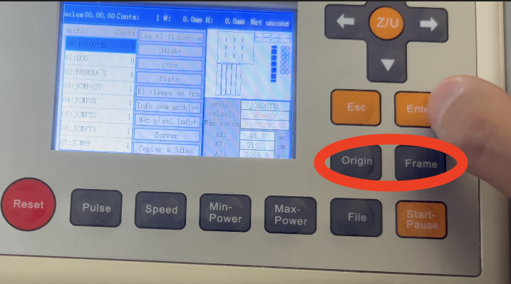
Power control
Now, this machine has 2 heads, this means it can make twice the same thing in just one cut. to control the heads there are 2 knobs which control the power of each head, if you put 100% on both, both will cut and so with just one. In my case I used just one so I gave 60% to the first one. Also there is a second safety check for the heads, a medium white button, this will turn on the laser.
And now you can click on start.
NOTE, do not look directly to the laser, and be careful with the smell, it smells really bad.
The final product
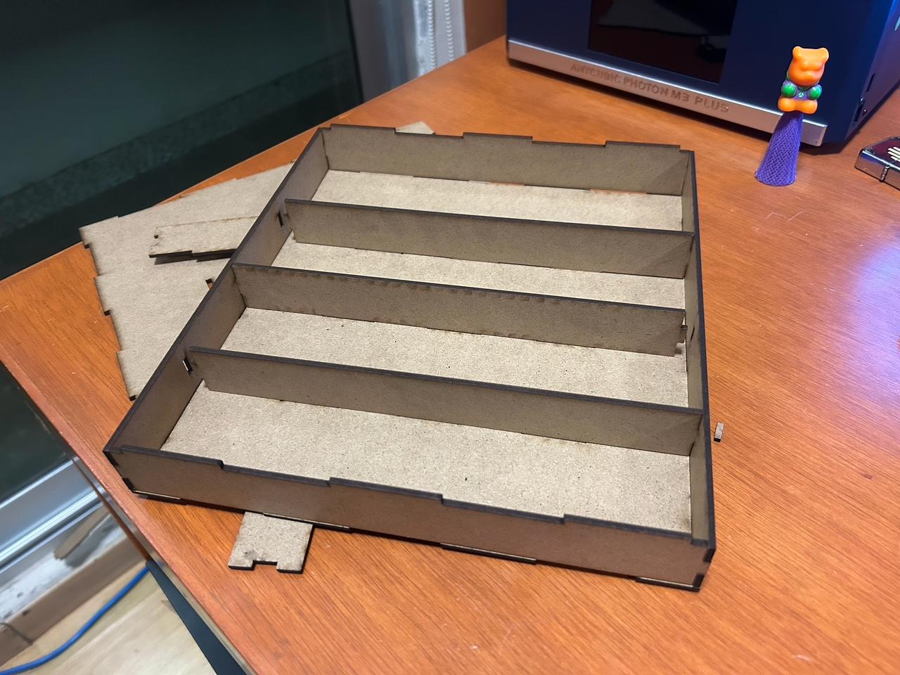
This is supposed to be a cutlery organizer, but since the MDF is not compatible with food or the things you use for eating, I will have to change the material.
What did I do
Once we know what materials can we cut, we have to know what tu cut (design), the challenge for this week is making a parametric design.
But what in this world is a parametric design? well there is the
easy answer and the not very easy answer is: a making a design according to some initial parameters.
This means its has to be with equations and numbers and some complex mathematics, This allows you creating very complex designs on a easy way and the best par for me:
editing it by just moving 2 or 3 parameters (or the number of initial parameter you establish). Everything on a parametric design is connected to this parameters.
Honestly right now I don't understand how is it applied to architecture and that kind of things (because if you look for some examples on the internet there are just structures and buildings, etc.)
just like this
and I mean, look a that I haven't seen enough you tube tutorial to understand something like that. AND in my local class they asked us to make something like "lego" some pieces that changing some numbers you can kind of "scale" it,
bt keeping some equal measurements so you can assemble them.
keeping that on mind and the urgency of having to make something to the end of the week I'm stressed because I haven't thought on a good idea.
Here are some ideas
- Making boxes following the "lego" concept
- A scalable moving wave moving sculpture.
- A clock
- Making a scalable gear moving figure
- flat pieces
- and ... thats it
I tried the box, and a hyperbolic paraboloid but it didn't work. The box wasn't parametric enough for me, the only thing that could have changed was the scale, and the hyperbolic paraboloid couldn't be done on SolidWorks,
also the parabolic surface was not be cut with the laser because it had 2 ends (because it was a curve), not to mention that marking the half heights to assembly the flats part was very difficult to solid and that requires integrating a function.
That's why I decided to make a cutlery organizer (I need one and this is a good opportunity).
Making the design
In the second week I explained how to create a design on SolidWorks, what I will explain here is how to work with equations on SolidWorks. The main point here is how to make it parametric. Taking the definition I just wrote, A cutlery organizer is a good option (specially because I need one) and making it parametric means making some editable variables like the height, With, spaces, etc, editable. And Some every other distance depending on the editable variables. In SolidWorks it looks something like this:
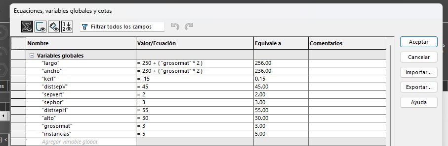
In this first image are the editable variables, on this ones depends the hole design
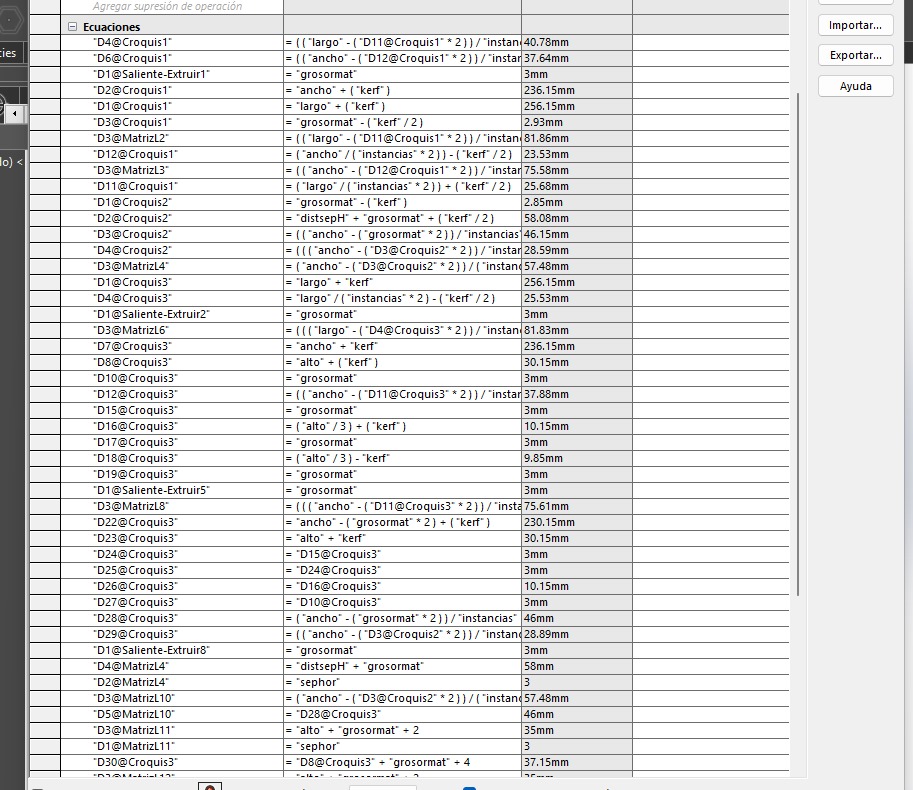
In this second image are the calculus on the dimentions anr arrays to make everything work based on the editable variables.
NOTE, it is very interesting how Solid let you put equations in arrays to tell how many elements you want or what separation between them you want.
The file
Saving the file
To make a file to cut with the laser, you have to make sure to work only on 2D, this means make every piece ona flat way. Once you have it like that, and finished the design, you will save the work as a SolidWork piece so you can keep editing it or creating new pieces, and save it in DXF. Make sure to be on a flat view before saving it on a DXF file, Solid will take as default the actual view of the work space.
Vinyl cuter machine
Making the file
As I don't know how to draw I took an image from the internet and traced it with illustrator edit it to the dimentions I wanted and saved the file in SVG file.
Here is the SVG file
Preparing the machine
This machine is what teh name says, cuts and draws over vinyl. It works basically with a head where you put the cutter or the marker, a kind of plate, where you place the vinyl to cut and a screen en some buttons to communicate with the machine. To use this you will need to cut the piece of vinyl you will use and paste it to the plate with a spray glue. Once done pasting the vinyl to the plate, you will place the pate on the rollers of the machine.
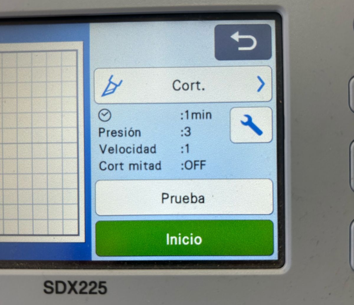
Note, this machine has two parameters to calibrate when cutting, the speed and the pressure applied to the vinyl. Is important to take into account the velocity to give the machine time to make the tiny details of the design. And the pressures is also very important, it has to be enough to cut trough the vinyl and not cut the plate, there are also many different types of vinyl that need different pressures of cut. In this case those parameters where.
Placing the plate on the red circles.
NOTE, DO NOT force the plate to get in to the rollers, once placed just click on the button with the grid on the control panel of the machine, (You can damage the machine if you force the rollers). Clicking that button will automatically activate the rollers and roll the plate in to its position.
Now in my case I used a USB to give the machine my file, with the plate inserted, is a very intuitive interface to edit the cut, you can scale it, add new forms and many other things. Click on next, select what you want to do and start.
Let it finish, once finished CLICK on the same grid button to release the plate form the rollers, NEVER take it your self. And clean with isopropyl alcohol the plate.
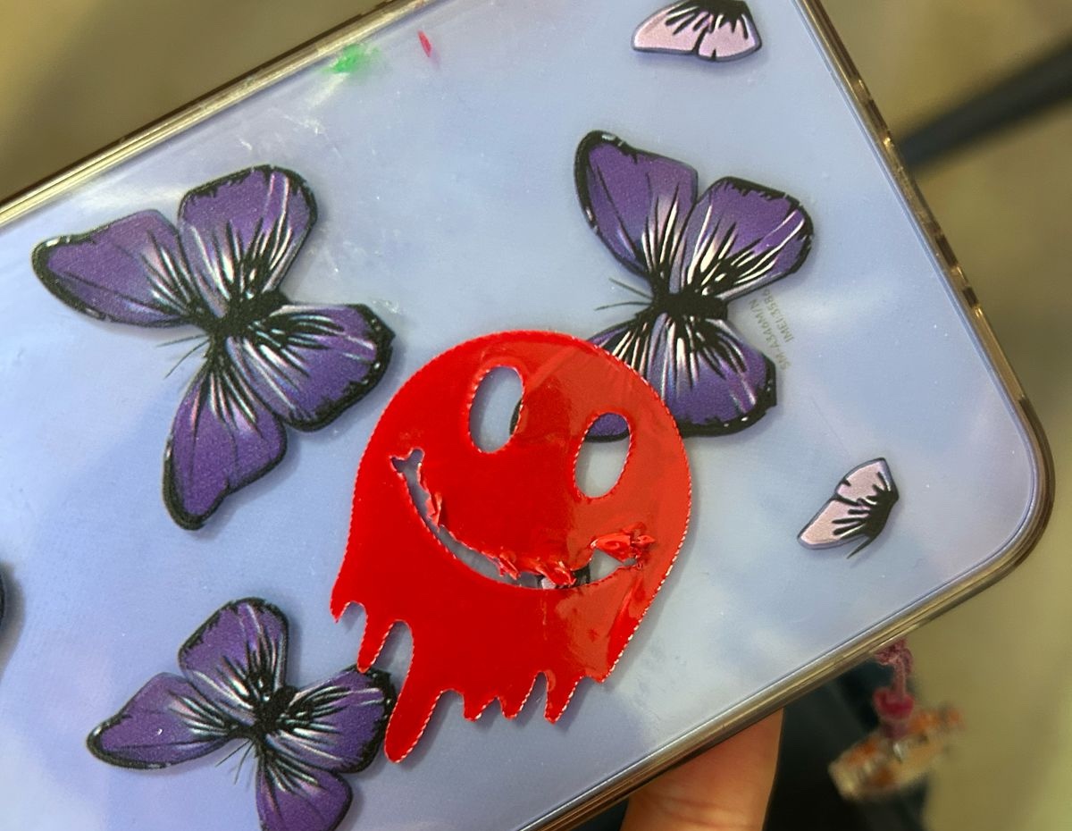
The final result
Errors
I had to make 2 times the organizer just because a bad design, the mdf plates fixed perfectly except for the fact that an equation was wrong and the walls didn't fit, so I re made the design
and cut again.
The sticker was also to big the first time it didn't fit on my vinyl piece, so I gave some measures on Illustrator and cut it again.