Week 2. Computer aided design
Basic understanding of computer aided design
There are many types of computer aided design softwares, but the main difference between them is the way you create solid elements and how you work with them. Some popular examples are:
-
Blender
This one works basically with meshes and you can manipulate those meshes using their faces, borders and vertex. This kind of program is most used to create characters, videos, films, and almost anything without exact measures. -
SolidWorks
This one works in planes (xy, yz ,xz), in those planes you need to draw sketches in 2D of the solids you want to make, and then you can extrude them in many different ways (straight, revolve, sweep, etc), this program usually doesn't works with meshes but it is use for precise designs, just like the one I made, so I used this kind of programs. -
Rhinoceros
This kind of program is like a combination between the previous ones, works on planes, but not with sketches, even though you can turn closed lines into solids, Once you have the solid object you can turn it into a mesh. This program can also work with exact measures, however once you end doing the lines or solid, you can not edit it precisely, you have either, make it again or use a subprogram called grasshopper. This program is most used for architecture designs.
How to decide which program to use
That basically depends on what do you want to make, in my case I needed to create an exact piece and I've been working with SolidWorks for a few months, so I'm used to its commands and interface.
Also, the way of editing anything is very easy, doesn't matter if is the first thing you draw you can easily edit it, and everything related to it will else be modified, if it needs it.
Another aspect to decide for this tool is the predefined tool it has, for example, the screw thread in the different standards (ISO, ANSI, etc), but not only screw threads, it also has gears, screws, nuts, etc.
In a few words it is a very complete and precise program.
Start using SolidWorks
The very first step is to buy and install the SolidWorks app, I'm one of the thousands lucky persons who can download it with the school account. Once you installed and opened it, there will be a menu with 3 main options, piece, drawing, and assembly.
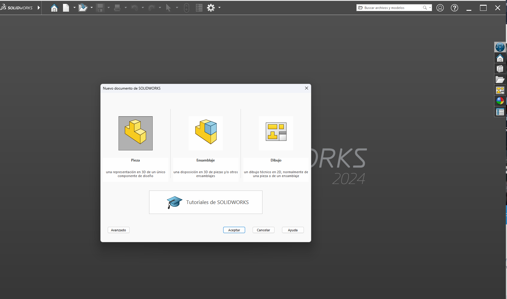
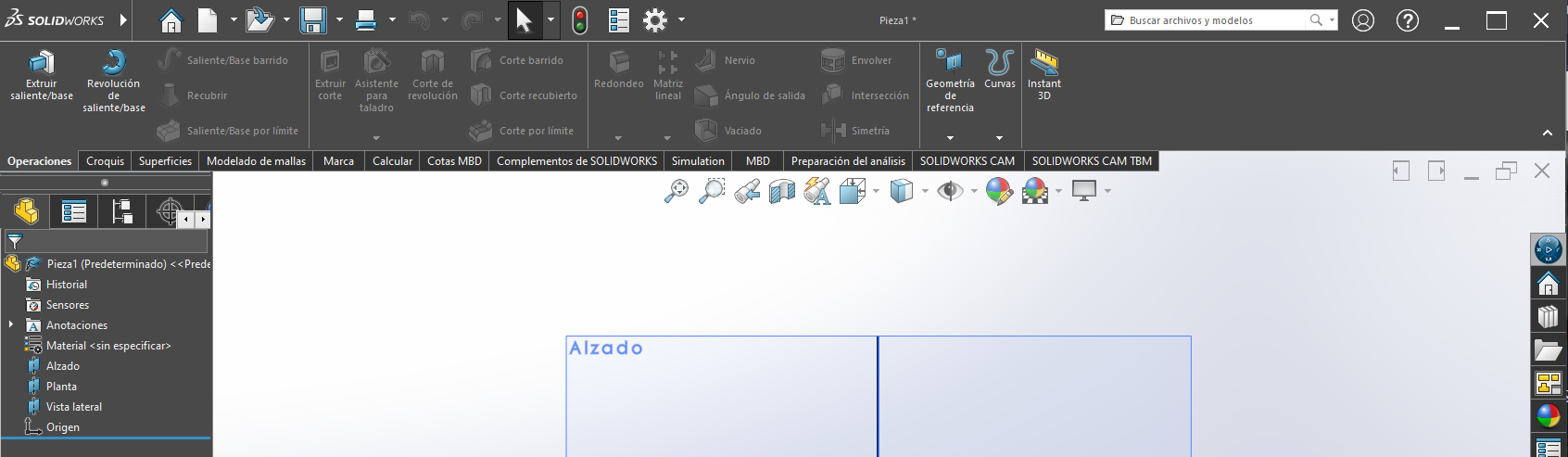
In my case I did a single piece (here in SolidWorks), so click on the piece option. Once you clicked it, a new window appears, this window is the work space and there are the 3 main planes where you can start (the blue square and the blue lines), on the very center of the window. On the left side will be the operations content tree. Here will be the historical elements you made, the default ones and the self made.
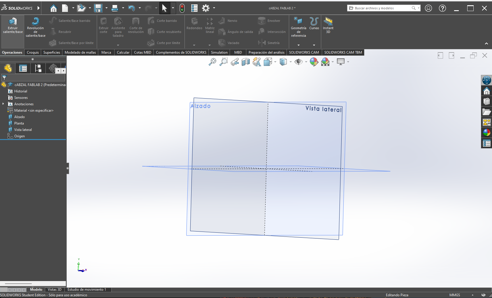
On the upper side will be the possible operations divided on categories:
-
Solids
Everything to create and manipulate the solid elements (extrude, revolve, sweep, etc). -
Sketches
Has everything to create 2D sketches (rule, basic forms, mirror, etc)
- etc
Creating my piece
Create a sketch
Using this tools, we can start creating our first sketch, It doesn't matter that much (in this case) in which plane we start drawing, however the recommendation is to orientate the piece on the correct way.
I decided to start on the front plane because it was the first option.
As I will only be using the straight extrusion I can draw almost all my pieces on the same sketch.
Now we have to deconstruct our piece on basic forms, like squares, circles, etc, That's why I started with 2 circles, and inside each circle, another circle with its correspondent dimensions
(The radius, distance between them and distance to the origin), and putting the horizontal restriction between both circles and the origin(This will block them on the same horizontal of the origin).
Then we have to add a straight slot around the main circles, so the outside area of the circles gets closed and not the inner area.
We are done with the 2D sketch, I can tell is alright because all the lines in the sketch turn black, that means everything is defined (In case a line is undefined it will turn blue),
I also can tell everything is ready to extrude because the area I want to extrude has a black tone, that means it`s completely closed (In case there were an open area it won't turn black and stay the same color as the background)
NOTE, You can make mathematical operations with the dimensions. In my case I wanted center both circles, instead of diving it`s distance on a half, I just wrote the equal (=) sign (this tells the program I`m going to introduce an equation), selected the dimension I want to divide, wrote a slash (/), and entered the number I wanted to divide by. Now the dimension has summation sign which indicates, it has a equation instead of a single number.
Creating a solid
It`s time to extrude the sketch, make sure to get out of the sketch, you can see you are inside the sketch because on the right top corner of the workspace are the out button of the sketch and the cancel button
or, because it won`t let you use any tool but the sketch tools. Now that we are out, click on the "Operations" menu, the first option is the one we need. click on it and it will ask you to select the sketch tou want to extrude
(You can select the sketch before by just clicking a line or directly on the operations tree).
NOTE, sometimes by default it activates a "laminar operation" and ir makes strange things, you just have to un select it and click on the selected contours, this option will remark the closed contour on
Once selected it will make a preview of the solid, In my case I activated the 2 end position because I want the piece to be on the exact centre and symmetrical, gave my desired dimensions and click on the check mark
NOTE 2, There are many default parameters like the origin of the extrusion, and the ending point of the extrusion, his parameters will stay as the default.
Making the rest of the pieces
We can repeat the same process for every part of the piece, just make sure to select the right plane.
For my second part I used the same plane, made my basic 2D form but I have two main advantages here, as the main piece is on the same plane I can take it as a reference for the actual sketch by selecting a line to make it my reference.
So I start my figure taking the solid as a reference, click on the line of the solid and a line on my sketch, give it a small separation, enough to not being able to see it but not touching the piece. This step will be very important late.
The second different thing here is the distance of extruding, the default one is to a given distance, this time will be to a plane/face, this option will use as the reference the given face, so if you edit the main piece this piece will also change.
For the 3th piece will be the same as the first and the second, but the different thing here will be the sketch plane, instead of selecting one of the default planes, we will be using a face where we want to create the sketch.
You just have to select the sketch tool, and click on the face.
Making the holes on my piece
For this process we`ll be making sketches on the faces where we need the holes. Once we have the sketches we will put dots, and align them as we need, if the holes are symmetrical I like doing just one half and use the mirror tool, to duplicate them
on the other side. For this we need to define a constructive line right in the middle on the dots area (this will be our reference to mirror them).
NOTE, the constructive line is a doted line which is mostly used like a guide, it can not create extrusion areas.
The next step is just using the smart fastener tool, this helps you create regulated holes based on a sketch. Select the desire sketch with dots, click on the tool, modify the specifications (regulation institution, diameter, depth, etc)
and check mark.
NOTE, this option allows you to select which solids you want to affect with the operation, in my case I have more than one solid, so I selected "all" this will make the hole on every solid it goes through within the given parameters.
To make more specifics forms of holes, there is a different way of doing them, even easier. Select the sketch face, create the forms of the holes and use the tool extrude cut, this will ask you for the sketch of the holes, the solid in which you want to
extrude the cut and the depth of the cut. Or in this case, as we want it to trough all the solid, we select the option "through all" and that`s all.
The files
Save and import the model
Saving the work is a very important part of the process, if you don't want to do it all over again if anything happens. For this we just hae to go to the very top of the work space and search for the "save" icon There you can find the:
-
save
Option which saves the work as the predefined file of SolidWorks, in this case will be "sldprt" SolidWorksPart. -
save as
Option that allows you to save your work with a different type of file, like dxf, stl, fbx, STEP, and many many other. -
save all
As can be read, saves every solid file you have open.
Important note
SolidWorks can make isolated parts and add them to a assembly to make almost anything. However, in order to be able to create the assembly, you have to design each piece on different files and them join them on the assembly. In my case I made the entire assembly on the piece, this means I can not manipulate each part separately. That's why I imported the sldprt file to fusion, a very similar computer aided design program. As this program works with sldprt files, and has the advantage of separate each piece to manipulate it separately I did it and here is how I did it.
Importing my file
I just opened fusion, clicked ctrl + o and searched for my file and opened it.
It takes a few seconds to prepare the file to open, and once it is ready a notification on the up right side appears, with a open button, click on it and voilá, done.
Now We can separate them into different pieces to create an assembly.
Creating an assembly
To create the assembly we have to first, make each piece a different one by clicking on the New component tool.
Once clicked a menu will open on the right side of the work space, we have to leave everything as the default option except for the "from bodies" option, we have to activate that option, so we can select a single solid.
and if you want change the name.
click on accept and we have our new component. Repeat the process with each component and done.
NOTE, as you can see, in my original design there is only one support, that support should be on both sides and we can mirror it now that we have that part as a single one. For this we will need a middle plane as reference to the mirror. Go to the construction tool, on the submenu there is an option that says "middle plane", once selected it will ask you for two planes or faces, in my case i selected the two sides of my main piece, so the plane creates exactly on the middle of the piece. With the plane we can go now to the crate menu, and select symmetry, this will ask you for the plane for the symmetry and the components to mirror. And done.
Now we have to tell each piece which will be it's position according to the other pieces. For this we will use the join tool, on the submenu "assembly". Once clicked a menu on the right side of the work space will open, with 2 main options:
-
Component 1
-
origin mode
This tells the program where you want to place the connector. -
simple
puts the connector just where you place it -
between faces
Place the connector between 2 faces -
force
asks you to select the place or faces
-
origin mode
-
Component 2
The same as the Component 1 but on the second component
I used the first one for the mane plate, and the supports on the sides. The tubes and the main piece is a different story because that joint is not fixed, I want the main piece to move along the tubes.
For this, we have to open once again the join menu, but this time we have to click on the second option (movement) of the upper menu of the tool menu. Once clicked the only option we can change we have to select
"slider" and now, on component 1 we have to click the option "between two faces" and select the circle faces of a tube, on the second component select both circle faces.
As it is a nonfixed joint we can change many more parameters, but I just changes the limits of joint, on the "movement" menu. Minimum = -180mm and Maximum = 180mm.
This measures because the total length of the tube are 200mm minus the half of the main piece, and some space.
Voilá, we have our assembly with movement.
The file
Creating my "render"
On this part I stayed on Fusion, because I already had the assembly. For this you have to go to the Design button on the top left side of the interface, click on the letters and look for the render option, click on it and a new interface will appear, in this new workspace, on the upper menu will appear the sections:
-
configurations
-
Physic material
Select the material of the piece, metal, plastic, glass. -
Aspect
Select the aspect to modify the color or texture of the piece, based on the material. -
scene configuration
changes the scene background o color -
stickers
Adds sticker to the pieces -
Textures
Gives the piece a desired texture
-
Physic material
-
Canvas rendering
-
Canvas rendering
renders the complete workspace. -
Canvas rendering configurations
As it's name says -
Save image
Will save the image as is on the workspace within the given configurations.
-
Canvas rendering
-
render
Makes the render
The first step
First we have to give each piece it's specific material (metal, glass, plastic, etc). Click on the "configuration" section and the first option "physic material". Once clicked the option a menu on the right side of the workspace will open, it contains carpets with all the default materials of fusion, look for your desire one and drag it until the piece that will have that material. Repeat the process with every Component. In y case I used, steel, aluminum and plastic.
The second step
Is giving the aspects to the components, same process as the previous one, on the respective tool. In this case I used, crystal for the tubes and 3D black plastic for the main component. The aluminum one stayed the same.
The third step
Is moving the assembly to the position you want to render and click on "render", it will open a menu where you can chose between the different types of images you can make, I choose personalized, gave the size of the image, click on local rendering, standar and render, it will start creating the render and place a preview in the bottom of the work space. Once it's done click on the preview to download the image.
NOTE, I tried doing the render this way but the image was ver pixeled.
So I tried clicking on the canvas rendering, that literally renders the hole workspace, Moved the assembly to the position I wanted to render and click on "capture image", just clicked on accept on the first popup, and on the second popup clicked on "save on my device" and save.
This image was way better than the first one and still not that heavy.
Final Product
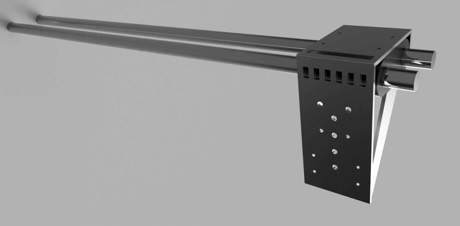
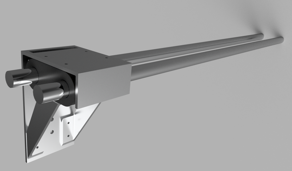
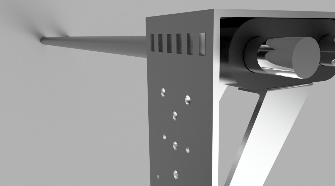
What ... is this piece?
Well, I though this piece to be the main head of the first machine I thought as my final project. As can bee seen on the piece, this head consisted by 2 tubes where the head will move. The main piece, will support the first plate (the one with the holes) and the supports will keep the main plate in its place. Of course this is just a sketch of what I want to do but yeah.
2D design
For the 2D design I used Adobe Illustrator, I've Being using it for a few months and I'm already kind of familiarized with the interface and commands. This was much easier than the 3D model. The idea was to represent the final project on a single image (no words). For this I just opened a new work on Illustrator, nothing special, just the default sizes. Created a circle with the eclipse tool. The I used the "pen" tool to crate my first figure, one click and the line starts, move the mouse and on the second click, if you keep it clicked, you can make a curve out of the same line, realize the click and keep drawing the figure.
And then used the "repeat" tool on the objet menu to create a linear matrix and repeat this same draw.
To give some color to the infill, just selected the figure I want to put some color and on the right panel clicked on the "infill" colored square this will open the colors menu and just select the one you like.
The rest was just question of using basic shapes and change the infill colors, there's a line in which instead of changing the infill color I just clicked on "trace" colored squared, and the same colors appeared.
Now, as you can see, there the 3D piece on a 2D form. Teh way of bringing a 3D design to a 2D design it's quite simple. You just have to open the piece on SolidWorks, click on new, drawing it will open the configuration
menu for the drawings, click on personalized so it is completely empty. Once created the file, on the right side will be the different views of the model.
Drag the one you need and place it. Click on the model to modify the scale on the left side of the workspace by looking for the scale option, personalized and the one you need.
Then save the file as a Illustrator file and open it on illustrator, it will open it as a new one just copy and paste it on the one you are working on and edit it. Of course save it and export it on the needed format.
The final result
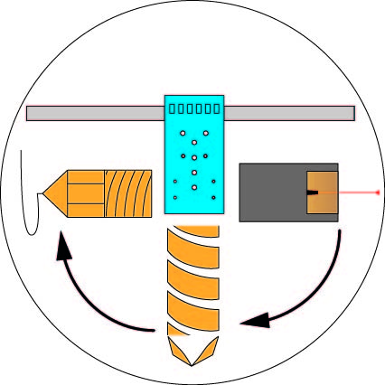
Quite ugly, but it was hand made so...
The file
How did I compressed the videos?
MAGIC!!!!
Just kidding, I used imovie, I looked the hole day for a way of compressing the videos and the easiest way was imovie. Record a very short video, cut some parts on imovie and then export it with low specifications.
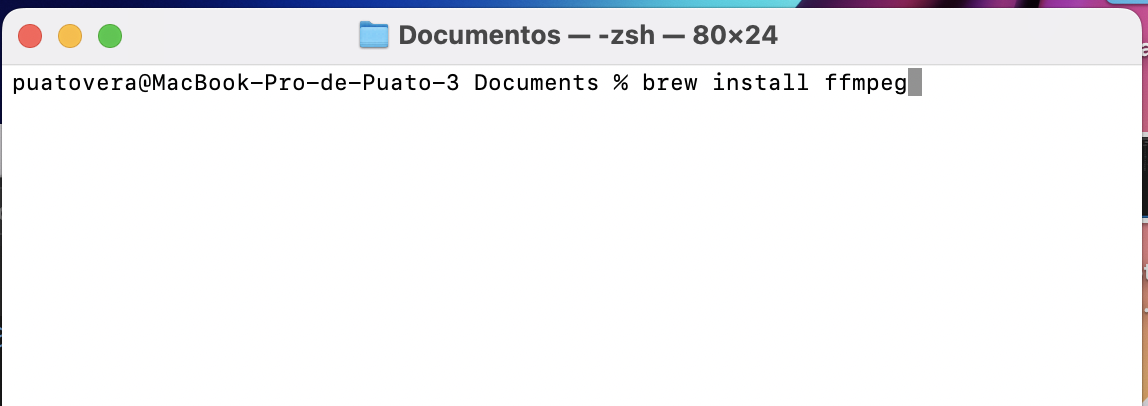
The second option
As this option didn't work (because the videos still around 2 MB) I had to re compress the videos using ffmpeg. This program is like git, the way of installing it and communicating with it is through the consol. To install ffmpeg you just write this command on the consol and wait until it finish.
Using ffmpeg is very easy, many commands are composed by an inout route, what you want to do and the output name. For example:
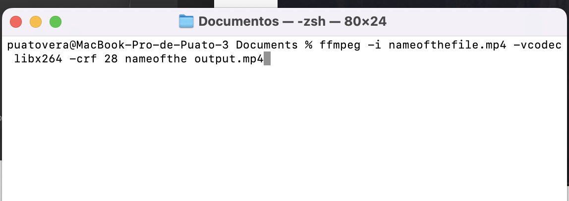
what this command does is, look for the name of the file, and reduce the bit frame of the video and make a new file with the output name and the ne specifications.
Notes, you can not write the same output name as the input name.
It's easier to go to the file route on the consol and then work there than writing the route.
Notes for myself
- DON'T overthink every thing, just read the instructions and make it, just do it, but not the day after the dead line, make it earlier.
- Making animations is more confusing than I thought, I tried doing one but as I overthought I didn't had time to search how to do it.
- imovie still being a great option to work with videos, at least the las hours of the deadline.
- And PLEASE finish the web site.