Input Devices
Input devices are components that gather data from the physical world and convert it into electrical signals that a microcontroller can interpret. These signals, whether analog or digital, allow the system to interact with its surroundings, detect changes, and execute programmed tasks accordingly. Typical input data include movement, light, pressure, sound, temperature, and more. Once processed, this data supports automated responses in embedded systems, making input devices fundamental in mechatronics.
Sensor vs Transducer
Although the terms sensor and transducer are often used interchangeably, they refer to slightly different concepts. A sensor specifically detects physical properties (e.g., temperature, light, or pressure) and outputs readable signals. In contrast, a transducer is a broader term for any device that converts one form of energy into another, commonly physical into electrical or vice versa.
| Feature | Sensor | Transducer | Active Transducer | Passive Transducer |
|---|---|---|---|---|
| Definition | Detects and measures physical properties | Converts one form of energy into another | Generates its own electrical signal from physical input | Modifies external voltage in response to physical input |
| Power Source | May or may not require power | Usually needs power | Does not require external power | Requires external power |
| Output | Readable signals (voltage, current) | Electrical signal or energy change | Self-generated electrical output | Modifies existing electrical signal |
| Examples | Temperature, light, pressure sensors | Thermocouple, microphone, piezoelectric disc | Photovoltaic cell, thermocouple | Thermistor, LDR, capacitive sensors |
In summary, input devices provide the bridge between the physical environment and microcontroller-based systems.
Microcontroller Input Signals Overview
Microcontrollers receive input signals from various devices and sensors, which can be broadly categorized as digital or analog.
- Digital Inputs: Represent binary states (HIGH/LOW or 1/0). These are typically used with switches, buttons, or digital sensors that output a clear ON/OFF signal.
- Analog Inputs: Represent a range of values, often read through an ADC (Analog-to-Digital Converter). This is useful for sensors that output varying voltages depending on the physical condition being measured, like temperature or light intensity.
Analog-to-Digital Conversion (ADC)
An ADC converts a continuous analog voltage signal into a digital value that a microcontroller can process. This is done by sampling the input voltage and assigning it a numeric value based on the resolution of the ADC, typically 8, 10, or 12 bits. For example, a 10-bit ADC can represent 1024 discrete values, mapping voltages across a 0–5V range into values from 0 to 1023.
Figure 1: ADC operation diagram.
Sensor Communication Protocols
Not all sensors provide analog or direct digital signals. Many modern sensors use communication protocols such as I2C, SPI, or UART to send more complex data. These protocols allow microcontrollers to communicate with multiple peripherals efficiently.
I2C vs SPI vs UART
Each protocol has unique characteristics in terms of wiring, speed, and use case. Here’s a quick overview:
| Feature | I2C | SPI | UART |
|---|---|---|---|
| Wires Required | 2 (SDA, SCL) | 4 (MISO, MOSI, SCK, SS) | 2 (TX, RX) |
| Speed | Medium | High | Medium |
| Multi-device Support | Yes (addressed) | Yes (via SS pins) | Typically, point-to-point |
| Complexity | Moderate | High | Low |
| Use Case | Multiple slow devices | Fast communication | Simple serial devices |
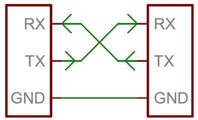
Figure 4: Wiring for UART.
For more info, click here to go to the group assignment website. For this week’s assignment, I will be working with the ESP32 board I developed in Week 8. I will connect three different input devices: a joystick module, an ultrasonic sensor (HC-SR04), and an accelerometer/gyroscope sensor (MPU6050). The goal is to demonstrate a variety of sensor types. I will begin by simulating the setup in Wokwi, then walk through the code, and finally show the working physical circuit (along with a small preview of the future of final project).
Wokwi simulation and code explanation
My initial plan was to connect and simulate all the sensors together in Wokwi, but the free version could not handle the processing load. So, I decided to split the code by components to run each one separately. This also helped me analyze each section more clearly. At the end, I will combine everything and show the full physical circuit in action.
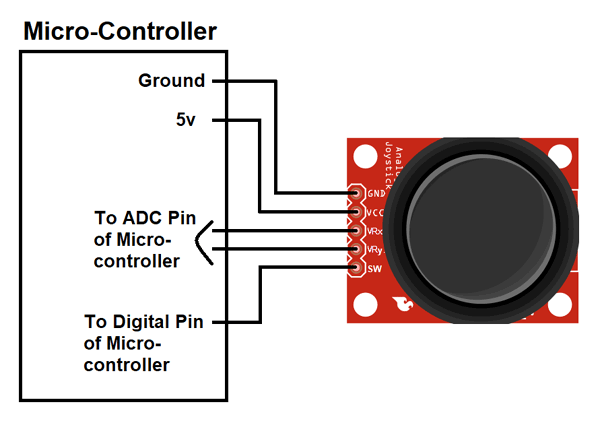
Joystick Module
A joystick module typically consists of two potentiometers for X and Y axis detection, and a push button for click input. Each potentiometer varies its resistance based on the physical position of the stick, generating an analog voltage that corresponds to its displacement. These analog signals are connected to the ESP32’s analog input pins, where an ADC converts them into digital values. The button acts as a digital input, pulling the signal LOW when pressed, which can be read using a digital input pin configured with internal pull-up.
            // Analog input pins for X and Y axes of the joystick
            #define JOYSTICK_X_PIN 34
            #define JOYSTICK_Y_PIN 35

            // Digital input pin for the joystick button
            #define JOYSTICK_BUTTON_PIN 32

            // Timing variables to control the reading interval
            unsigned long lastReadTime = 0;
            const unsigned long readInterval = 1000; // Interval set to 1 seconds

            void setup() {
              Serial.begin(115200);

              // The button uses an internal pull-up resistor.
              // When pressed, it connects to GND (reads LOW).
              pinMode(JOYSTICK_BUTTON_PIN, INPUT_PULLUP);
            }

            void loop() {
              unsigned long currentTime = millis();

              // This block ensures that readings are taken every 1 seconds
              if (currentTime - lastReadTime >= readInterval) {
                lastReadTime = currentTime;

                // Read analog values from the joystick's X and Y axes
                int xValue = analogRead(JOYSTICK_X_PIN);
                int yValue = analogRead(JOYSTICK_Y_PIN);

                // The button is active LOW, so we check for a LOW signal to detect a press
                bool buttonPressed = digitalRead(JOYSTICK_BUTTON_PIN) == LOW;

                // Output the values to the Serial Monitor for analysis
                Serial.println("=== Joystick ===");
                Serial.print("X: ");
                Serial.print(xValue);
                Serial.print(" | Y: ");
                Serial.print(yValue);
                Serial.print(" | Button: ");
                Serial.println(buttonPressed ? "Pressed" : "Released");
                Serial.println("================\n");
              }
            }
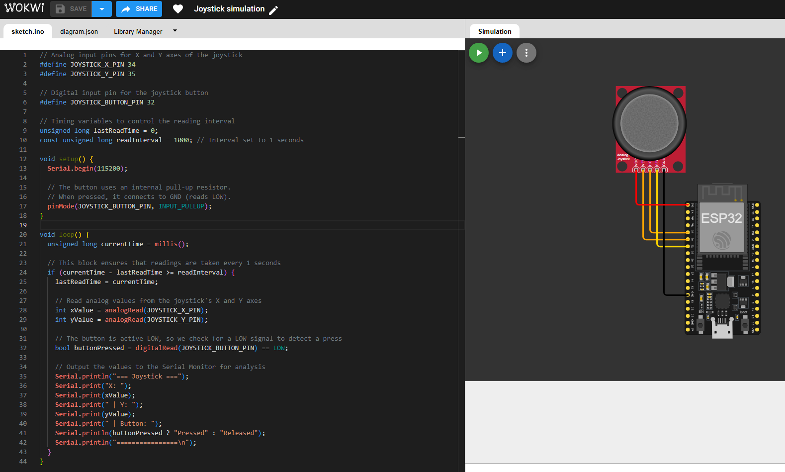
The code reads the position and button state of a joystick connected to the ESP32. The X and Y axes are connected to analog input pins, while the button is connected to a digital input pin configured with an internal pull-up resistor. The loop() function uses the millis() function to control the timing of the readings, ensuring that data is collected every one second. This method is preferred over delay() because it allows the microcontroller to remain responsive and continue executing other tasks between readings. Inside the timed block, the code reads the analog values from the joystick axes and checks the digital state of the button (active LOW when pressed). The values are then printed to the Serial Monitor for real-time observation and analysis. Click here to go to the Wokwi simulation.
Ultrasonic Sensor (HC-SR04)
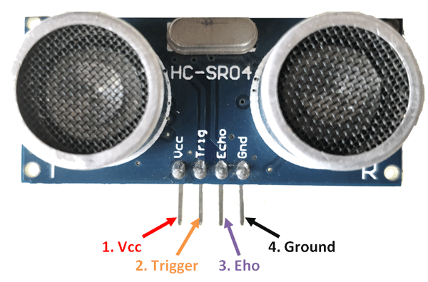
The HC-SR04 measures distance by emitting ultrasonic sound waves through the 'TRIG' pin and waiting for the echo to return to the 'ECHO' pin. The TRIG pin is controlled by the microcontroller and requires a 10-microsecond HIGH pulse to initiate a measurement. The sensor then emits an ultrasonic burst and sets the ECHO pin HIGH for a duration proportional to the time it takes for the sound to bounce back from an object. The microcontroller measures this pulse duration and calculates the distance using the speed of sound. This setup requires precise timing and is handled using functions like `pulseIn()`.
            // Ultrasonic sensor pin definitions
            #define TRIG_PIN 27
            #define ECHO_PIN 26

            // Timing variables to control the reading interval
            unsigned long lastReadTime = 0;
            const unsigned long readInterval = 1000; // Interval set to 1 seconds

            void setup() {
              Serial.begin(115200);

              // Set TRIG as output (to send the pulse)
              // and ECHO as input (to receive the reflected signal)
              pinMode(TRIG_PIN, OUTPUT);
              pinMode(ECHO_PIN, INPUT);
            }

            void loop() {
              unsigned long currentTime = millis();

              // Check if enough time has passed before taking a new reading
              if (currentTime - lastReadTime >= readInterval) {
                lastReadTime = currentTime;

                // Send a 10 µs HIGH pulse to TRIG to start measurement
                digitalWrite(TRIG_PIN, LOW);
                delayMicroseconds(2);
                digitalWrite(TRIG_PIN, HIGH);
                delayMicroseconds(10);
                digitalWrite(TRIG_PIN, LOW);

                // Measure the duration of the HIGH pulse received at ECHO
                long duration = pulseIn(ECHO_PIN, HIGH);

                // Convert duration to distance (in cm)
                // 0.0343 cm/µs is the speed of sound divided by 2 (go and return)
                float distanceCm = duration * 0.0343 / 2;

                // Print the measured distance to the Serial Monitor
                Serial.println("=== Ultrasonic Sensor ===");
                Serial.print("Distance: ");
                Serial.print(distanceCm);
                Serial.println(" cm");
                Serial.println("=========================\n");
              }
            }
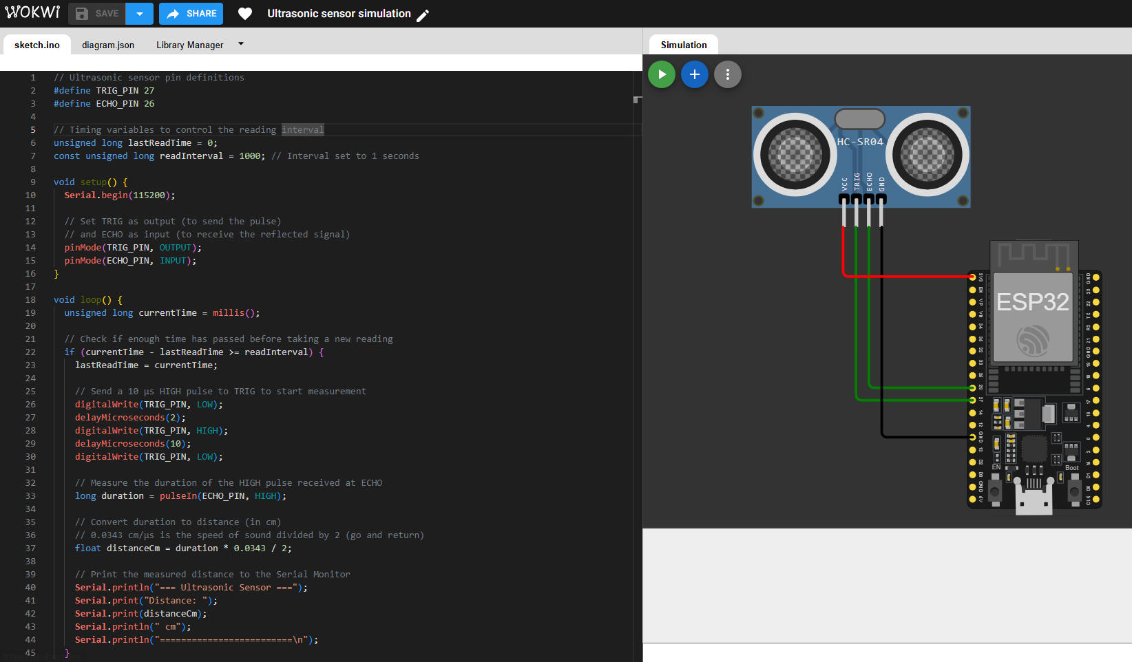
The code reads distance measurements from an ultrasonic sensor (HC-SR04) connected to the ESP32. The TRIG pin is used to send a short HIGH pulse that triggers the sensor to emit an ultrasonic wave. The ECHO pin then listens for the reflected wave and stays HIGH for a duration proportional to the distance of the object. The pulseIn() function measures this time, and the result is converted to centimeters using the speed of sound. To avoid constant reading and to keep the system efficient, the code uses millis() to trigger measurements every one second instead of using delay(), which would block other operations. The calculated distance is then printed to the Serial Monitor for analysis. Click here to go to the Wokwi simulation.
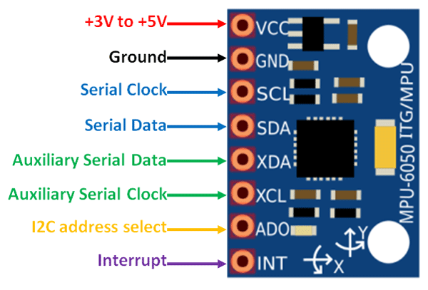
MPU6050 (Accelerometer and Gyroscope)
The MPU6050 is a 6-axis motion tracking sensor that combines a 3-axis accelerometer and a 3-axis gyroscope. It communicates with the microcontroller using the I²C protocol, which uses two lines: SDA (data) and SCL (clock). The sensor continuously monitors acceleration and angular velocity, then sends digital data through I²C when requested. The ESP32 reads this data using the Wire library and processes the values to detect motion, orientation, or tilt.
        #include <Wire.h>
        #include <Adafruit_MPU6050.h>
        #include <Adafruit_Sensor.h>

        // Create an object to handle the MPU6050 sensor
        Adafruit_MPU6050 mpu;

        // Timing variables for controlling how often the sensor is read
        unsigned long lastReadTime = 0;
        const unsigned long readInterval = 5000; // 5 seconds

        void setup() {
          Serial.begin(115200);
          delay(1000); // Small delay to stabilize serial and sensor startup

          // Initialize communication with the MPU6050 via I2C
          if (!mpu.begin()) {
            Serial.println("MPU6050 not found.");
            // Halt execution if the sensor doesn't respond
            while (1) delay(10);
          }

          // Configure sensor sensitivity (optional but useful for tuning)
          mpu.setAccelerometerRange(MPU6050_RANGE_8_G);
          mpu.setGyroRange(MPU6050_RANGE_500_DEG);
          mpu.setFilterBandwidth(MPU6050_BAND_21_HZ);
        }

        void loop() {
          unsigned long currentTime = millis();

          // Read sensor data only after the defined interval
          if (currentTime - lastReadTime >= readInterval) {
            lastReadTime = currentTime;

            // Get data from the accelerometer, gyroscope, and internal temp sensor
            sensors_event_t a, g, temp;
            mpu.getEvent(&a, &g, &temp);

            // Convert acceleration from m/s^2 to g by dividing by 9.81
            Serial.print("Accel (g) → X: ");
            Serial.print(a.acceleration.x / 9.81, 2);
            Serial.print(" Y: ");
            Serial.print(a.acceleration.y / 9.81, 2);
            Serial.print(" Z: ");
            Serial.println(a.acceleration.z / 9.81, 2);

            // Convert gyroscope from radians/s to degrees/s (1 rad ≈ 57.2958 degrees)
            Serial.print("Gyro (°/s) → X: ");
            Serial.print(g.gyro.x * 57.2958, 2);
            Serial.print(" Y: ");
            Serial.print(g.gyro.y * 57.2958, 2);
            Serial.print(" Z: ");
            Serial.println(g.gyro.z * 57.2958, 2);

            Serial.println("================\n");
          }
        }
The code reads acceleration and gyroscope data from an MPU6050 sensor connected to the ESP32 via the I²C protocol. The sensor is initialized in the setup() function, and its sensitivity settings are configured for both the accelerometer and gyroscope. The Adafruit MPU6050 library simplifies this process by handling the communication and register access internally. It automatically requests data from the sensor over I²C and returns it in a usable format through the getEvent() function. Without this library, the programmer would need to manually access specific memory registers inside the MPU6050, write commands to request data, and read the response using low-level I²C communication. In the loop(), the program uses the millis() function to read the sensor every five seconds. This longer interval was chosen specifically to avoid performance issues in Wokwi during simulation. The accelerometer values are converted from meters per second squared to g-forces by dividing by 9.81, while the gyroscope values are converted from radians per second to degrees per second using a fixed conversion factor. The results are printed to the Serial Monitor for analysis. Using millis() ensures that the ESP32 remains responsive between readings. Click here to go to the Wokwi simulation.
Unifying the codes and connections should look like this:
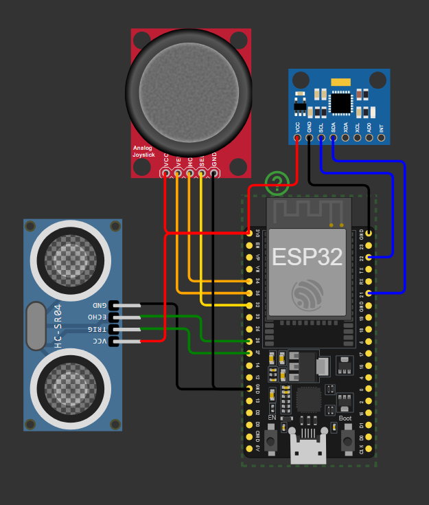
Figure 11: Unifying circuits
        #include <Wire.h>
        #include <Adafruit_MPU6050.h>
        #include <Adafruit_Sensor.h>

        // === Pin Definitions ===
        #define JOYSTICK_X_PIN 34     // Analog pin
        #define JOYSTICK_Y_PIN 35     // Analog pin
        #define JOYSTICK_BUTTON_PIN 32 // Digital pin

        #define TRIG_PIN 27           // Ultrasonic trigger pin
        #define ECHO_PIN 26           // Ultrasonic echo pin

        // === Sensor Object ===
        Adafruit_MPU6050 mpu;

        // === Timing Control ===
        unsigned long lastReadTime = 0;
        const unsigned long readInterval = 1000; // 1 seconds

        void setup() {
          Serial.begin(115200);
          delay(1000);

          // Joystick button as input with internal pull-up
          pinMode(JOYSTICK_BUTTON_PIN, INPUT_PULLUP);

          // Ultrasonic sensor pins
          pinMode(TRIG_PIN, OUTPUT);
          pinMode(ECHO_PIN, INPUT);

          // Initialize I2C communication and MPU6050
          if (!mpu.begin()) {
            Serial.println("MPU6050 not found. Check connections.");
            while (1) delay(10);
          }

          // Optional: Configure accelerometer and gyroscope range
          mpu.setAccelerometerRange(MPU6050_RANGE_8_G);
          mpu.setGyroRange(MPU6050_RANGE_500_DEG);
          mpu.setFilterBandwidth(MPU6050_BAND_21_HZ);
        }

        void loop() {
          unsigned long currentTime = millis();
          if (currentTime - lastReadTime >= readInterval) {
            lastReadTime = currentTime;

            // === Joystick Readings ===
            int xValue = analogRead(JOYSTICK_X_PIN);
            int yValue = analogRead(JOYSTICK_Y_PIN);
            bool buttonPressed = digitalRead(JOYSTICK_BUTTON_PIN) == LOW; // Active LOW

            // === Ultrasonic Distance Measurement ===
            digitalWrite(TRIG_PIN, LOW);
            delayMicroseconds(2);
            digitalWrite(TRIG_PIN, HIGH);
            delayMicroseconds(10);
            digitalWrite(TRIG_PIN, LOW);

            long duration = pulseIn(ECHO_PIN, HIGH);
            float distanceCm = duration * 0.0343 / 2; // Convert time to distance (cm)

            // === MPU6050 Sensor Readings ===
            sensors_event_t a, g, temp;
            mpu.getEvent(&a, &g, &temp); // Read all sensor values at once

            // === Serial Output ===
            Serial.println("=== Sensor Data ===");

            Serial.print("Joystick - X: ");
            Serial.print(xValue);
            Serial.print(" | Y: ");
            Serial.print(yValue);
            Serial.print(" | Button: ");
            Serial.println(buttonPressed ? "Pressed" : "Released");

            Serial.print("Ultrasonic Distance: ");
            Serial.print(distanceCm);
            Serial.println(" cm");

            // Convert acceleration from m/s^2 to g by dividing by 9.81
            Serial.print("Accel (g) → X: ");
            Serial.print(a.acceleration.x / 9.81, 2);
            Serial.print(" Y: ");
            Serial.print(a.acceleration.y / 9.81, 2);
            Serial.print(" Z: ");
            Serial.println(a.acceleration.z / 9.81, 2);

            // Convert gyroscope from radians/s to degrees/s (1 rad ≈ 57.2958 degrees)
            Serial.print("Gyro (°/s) → X: ");
            Serial.print(g.gyro.x * 57.2958, 2);
            Serial.print(" Y: ");
            Serial.print(g.gyro.y * 57.2958, 2);
            Serial.print(" Z: ");
            Serial.println(g.gyro.z * 57.2958, 2);

            Serial.println("================\n");
          }
        }
Although I have already explained the code in detail, the overall idea is as follows. This program uses an ESP32 to read data from three different input devices: a joystick, an ultrasonic sensor, and an MPU6050 accelerometer and gyroscope. Each sensor is connected through appropriate pins or communication protocols, and their values are collected at regular intervals using non-blocking timing with millis(). The joystick provides analog and digital input, the ultrasonic sensor measures distance using sound pulses, and the MPU6050 communicates over I2C to deliver motion data. All readings are printed to the Serial Monitor for observation and analysis.
Physical circuit
This is where a small issues came up due to a bit of carelessness. My board works, the modules work (actually nope), and I have everything I need to connect them... well, almost everything. I included some power pins on the board for both itself and external devices, but not enough xD. So, I had to use protoboard just to extend the power connections for the components.
Another issue is that my ultrasonic sensor is not working. It functions correctly in the simulation, and I have tried everything—including powering it with 5V and protecting the Echo pin using a 1k ohm resistor—but it still does not respond. Because of this, I will need to replace the component. In the meantime, I will demonstrate how the circuit works without the ultrasonic sensor:
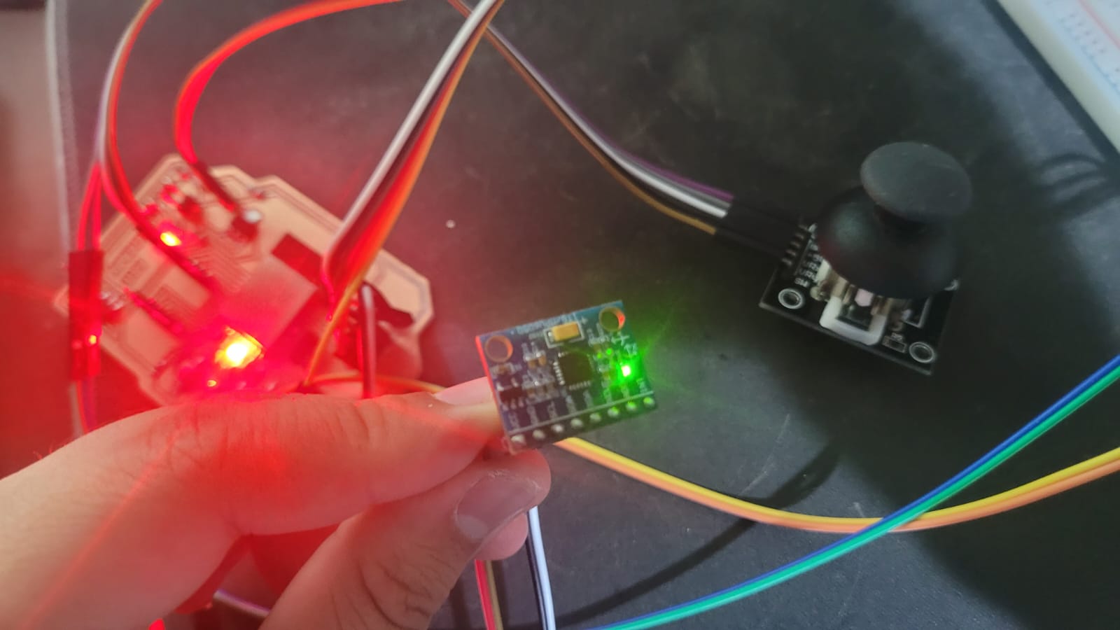
Figure 12: Physical circuit
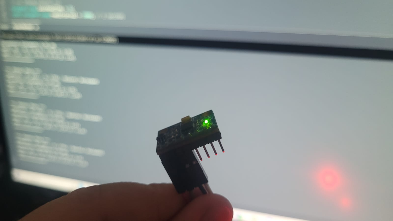
HEROSHOT!! Multiple input signals
LEARNINGS
Through both my academic coursework and independent projects, I have gained substantial experience in interpreting signals from a variety of transducers. In fact, when working with the MPU, I have retrieved measurement data without relying on the Adafruit library, instead accessing the sensor’s internal registers directly. However, a significant portion of the circuits I developed were constructed on a breadboard. Although this method is functional, it is not considered good engineering practice. This became evident when I attempted to connect the components to my custom-designed board. I had assumed that I had provided an adequate number of power supply connections, but this was not the case. As a result, I now understand the importance of carefully planning and evaluating my circuit designs to prevent such oversights in the future.