Output Devices
Output signals are the electrical signals generated by a microcontroller to drive external devices or indicate information. In digital electronics, a microcontroller’s output pin can be in one of two binary states: HIGH (logic 1) or LOW (logic 0). A HIGH output typically corresponds to a specific voltage level (e.g. 5 V or 3.3 V), while LOW corresponds to 0 V (ground). These HIGH/LOW states can represent binary data, and by switching an output pin on and off in a timed sequence, a microcontroller can send out a stream of bits (1s and 0s). For example, a microcontroller might output the bit sequence 10110010 by rapidly toggling a pin HIGH and LOW according to that binary pattern. Such bit sequences are the basis of digital communication with peripherals (for instance, sending data over a serial bus or toggling control signals).
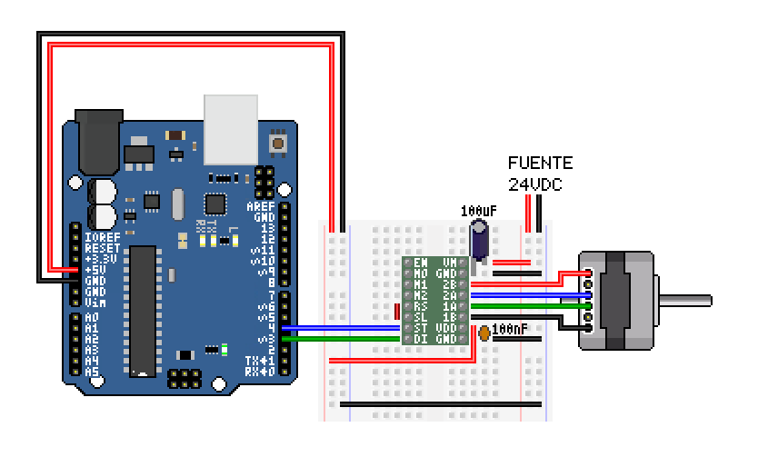
Figure 1: Microcontoller sending data to a driver that controls a steppper motor.
Beyond simple on/off signaling, microcontrollers often need to produce analog-like outputs. Since most microcontroller output pins are binary (either HIGH or LOW), one common technique to simulate analog voltages or waveforms is Pulse-Width Modulation (PWM). PWM involves outputting a rapid train of pulses and varying the duty cycle (the fraction of time the signal is HIGH in each cycle). By adjusting the duty cycle, the average voltage over time can mimic an analog level. For instance, a 50% duty cycle PWM (pin HIGH half the time, LOW half the time) yields an average output of about half the supply voltage. If this PWM signal is applied to a device like an LED or filtered by a simple electronic filter, it behaves similarly to a true analog voltage. In fact, the principle behind PWM-to-analog conversion is that the current or voltage seen by the load is proportional to the percentage of time the signal is on. This is widely used for controlling LED brightness or motor speed with fine granularity.
Using PWM, a microcontroller can also generate waveforms such as audio tones or even arbitrary signals. By rapidly changing the duty cycle according to a waveform pattern (for example, following the shape of a sine wave), the output can approximate that waveform. A classic example is producing a sinusoidal audio signal (like a musical note) from a microcontroller that lacks a true analog output. The microcontroller can output a high-frequency PWM whose duty cycle varies sinusoidally at the desired audio frequency. After passing through a speaker (which naturally filters high-frequency components) or an external low-pass filter, the result is a reasonable sine wave sound. This works because any periodic waveform can be decomposed into a sum of sinusoidal components (Fourier theory). A PWM signal contains a high-frequency carrier and harmonics; by smoothing out the high-frequency parts, the fundamental frequency remains. In other words, through techniques like PWM (or using a DAC if available), digital outputs can synthesize analog signals such as voltages, sounds, or other waveforms.
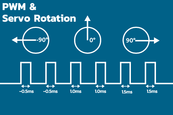
Figure 2: Laser cutter key components.
Devices
Output devices (often called actuators when they cause physical action) are components that take the output signals from a microcontroller and convert them into some form of action or feedback in the physical world. This action could be mechanical motion, light, sound, or any other physical effect. Below is an overview of various common output devices and how microcontrollers interface with them:
| Output Device | Signal Type & Frequency | Microcontroller Interface | Signal Interpretation Logic | Functionality in System |
|---|---|---|---|---|
| Servo Motor | PWM signal: 1–2 ms HIGH pulse in 20 ms frame (50 Hz) | Digital output pin with PWM (hardware/software) | Pulse width is measured internally; corresponds to specific angle (e.g., 1 ms = 0°, 1.5 ms = 90°, 2 ms = 180°) | Provides precise angular position control, ideal for animatronic joints or robotic limbs |
| Stepper Motor | Digital step pulses + direction bit; pulse frequency = speed | Digital pins to STEP and DIR inputs of stepper driver | Each rising edge on STEP triggers one motor step; DIR pin sets direction of rotation | Used for precise incremental rotation (e.g., in 3D printers, CNCs, or pan/tilt systems) |
| DC Motor | PWM signal for speed; digital HIGH/LOW or H-bridge for direction | PWM pin to driver enable, digital pins for direction control | Duty cycle sets average voltage (speed); H-bridge polarity determines rotation direction | Drives wheels, fans, or moving parts where continuous rotation is needed |
| Speaker/Buzzer | Square wave or modulated PWM (~20 Hz to 20 kHz), optionally audio DAC | Digital output for tone; optional amplifier for volume | Oscillating signal causes diaphragm to vibrate at set frequency, producing sound | Emits tones, alarms, or audio playback; used in user feedback and sound design |
| Single LED | Digital HIGH/LOW (on/off), or PWM for brightness | Digital output with series resistor, or PWM capable pin | ON when pin is HIGH, OFF when LOW; brightness varies with PWM duty cycle | Simple light indicators, signal feedback, or status notifications |
| RGB LED (NeoPixel) | Serial data stream at ~800 kHz (24-bit per LED) | One digital pin for chained data stream (uses strict timing) | First LED latches 24-bit color data (8 bits each R/G/B), passes remaining down chain | Full-color individually addressable lighting for visual effects and UI animations |
| LCD (Character) | 4-bit or 8-bit parallel data + control (RS, EN), or I2C/SPI via adapter | Digital output lines or I2C interface | Receives ASCII commands/data, displays characters or executes control instructions (e.g., clear, move cursor) | Displays static or scrolling text; simple visual data display for embedded systems |
| TFT Display | SPI (MOSI, SCK, CS, DC); data + command bytes + pixel buffer | Hardware SPI interface (high-speed); ~1-20 MHz | Receives drawing commands and pixel data; updates internal framebuffer to show graphics | Displays high-resolution color images, UI components, or dynamic animations |
| OLED Display | I2C or SPI digital communication; pixel address and data stream | Two-wire I2C (SDA/SCL) or SPI lines | Interprets bytes as memory updates for pixel map; displays text or bitmaps directly | Sharp, high-contrast visual output in small form-factor; ideal for compact displays |
| Solenoid | Digital HIGH/LOW (on/off activation signal) | Digital output through NPN transistor or MOSFET | HIGH energizes coil, producing magnetic field that actuates mechanical plunger | Performs binary physical action (push/pull) for locks, mechanisms, triggers |
| Relay | Digital HIGH energizes coil; relay toggles switch contact | Digital output with driver transistor or module | Energizing coil closes normally-open contact, enabling power routing | Enables microcontroller to control high-voltage/high-current devices safely |
| Linear Actuator | DC voltage or PWM + direction signals (varies by design) | Motor driver interface (e.g., H-bridge) or servo-style PWM | Voltage level or pulse duration determines extension; some models have limit switches | Performs push/pull motion for robotics, haptics, automation |
| Heater / Valve | Digital ON/OFF or analog PWM for regulation | Output via transistor or MOSFET with thermal control loop | Signal activates heating coil or opens valve; PWM regulates power input proportionally | Thermal actuation or fluid control in embedded environmental systems |
For more information, go to our group assignment.
This week, I will take a closer look at two specific output components: the GC9A01 TFT display and the PCA9685 servo driver module since they will be used in my final project (specifically, the animatronic head); and understanding their operation is crucial for successful integration. I will examine the type of signals they use, how the microcontroller interfaces with them, how they interpret those signals, and their basic functional logic in the system.
GC9A01 TFT Display (Round TFT Module)
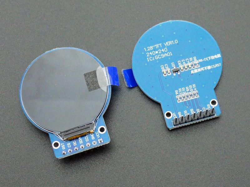
Figure 3: Laser cutter key components.
The GC9A01 is a display driver IC used in small circular or square TFT LCD modules, most commonly in 1.28-inch round displays with a resolution of 240×240 pixels. It supports 16-bit (RGB565) and 18-bit (RGB666) color formats, making it suitable for full-color graphics.
Communication and Signal Interface
This module uses a 4-wire SPI interface for communication with the microcontroller, plus control and power lines:
- MOSI (Master Out Slave In): Transfers pixel data and configuration commands.
- SCK (Serial Clock): Synchronizes data transmission.
- CS (Chip Select): Enables communication when pulled LOW.
- DC (Data/Command): Selects between command mode (LOW) and data mode (HIGH).
- RESET (RST): Hardware reset pin to ensure proper startup.
- Vcc / GND: Power supply (typically 3.3 V).
- LED/BLK: Optional backlight pin, often driven by PWM for brightness control.
The microcontroller (e.g., ESP32) typically uses hardware SPI at clock speeds up to 40 MHz to efficiently transfer data. A full-screen update at 16-bit color requires ~115 kB (240×240×2 bytes), making high SPI throughput essential for dynamic content.
Signal Processing and Functionality
The GC9A01 contains an internal GRAM (Graphics RAM) of approximately 130 kB, which stores the current pixel data. The microcontroller does not need to refresh the screen continuously; it updates only the portions that change.
A typical drawing sequence involves:
- 1. Sending a Column Address Set command with start/end indices.
- 2. Sending a Row Address Set command similarly.
- 3. Sending a Memory Write command followed by the pixel data stream.
These commands and data are interpreted by the GC9A01's internal logic, which maps them into its framebuffer and updates the LCD matrix accordingly.
z Servo Driver Module (16-Channel PWM)
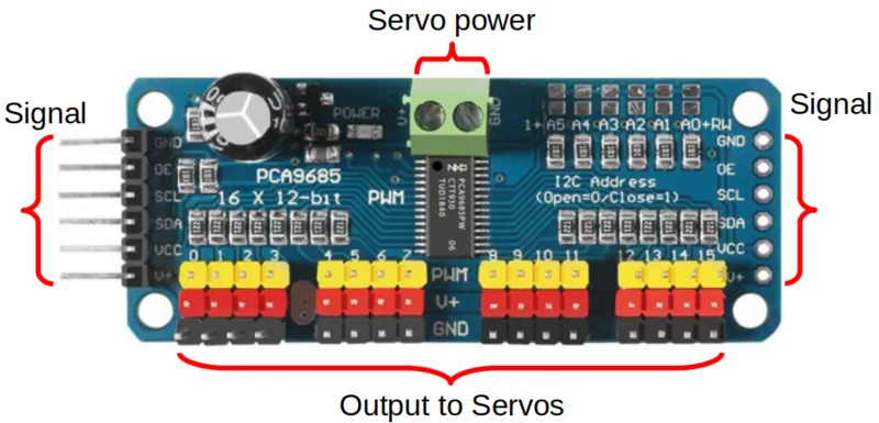
Figure 4: Laser cutter key components.
The PCA9685 is a 16-channel PWM generator with 12-bit resolution (4096 steps). It features a built-in oscillator and operates independently once configured, reducing the processing load on the microcontroller.
Communication and Microcontroller Interface
It communicates via the I²C protocol, using only two lines:
- SDA (Serial Data)
- SCL (Serial Clock)
Each device on the bus is addressed (default address: 0x40), and multiple PCA9685 modules can coexist on the same bus by configuring their address pins. This makes the system highly scalable and efficient in terms of pin usage.
Signal Generation Logic
The PCA9685 generates PWM signals by using an internal 12-bit counter that continuously counts from 0 to 4095. Each PWM cycle is divided into 4096 discrete time steps, allowing for precise duty cycle control on each of its 16 output channels.
For every channel, the PWM waveform is defined using two key 12-bit registers:
- ON register: Defines the counter value at which the output goes HIGH.
- OFF register: Defines when it transitions back to LOW.
This allows full control over both the duty cycle and phase shift, although in most servo applications, the ON value is set to 0, and only the OFF value is adjusted to define the pulse width.
Programming the devices
My initial plan was to connect and simulate both devices and some servos in Wokwi. However, Wokwi (and as far as I know, any software) does not have a built-in model for the GC9A01 TFT display or the PCA9685 PWM driver. This means I cannot directly simulate those specific components with full fidelity. There are community-contributed “custom chips” for some parts (for example, a PCA9685 simulation has been attempted by the community), but they may require additional setup and might not exactly match real-world behavior.
Given these limitations, I will start by testing code for each output device individually and already physically. For the TFT Display my goal is to make a simple code that alternates between 2 images using millis() so that the code is not blocking. Then for the PCA9685 I will only make a sequence with 6 servos attached to the module. I plan to use two libraries, Adafruit_PWMServoDriver for PCA9685 and TFT_eSPI for the GC9A01; I will use these to facilitate the use of both devices.
TFT Display Code
To operate the TFT displays, we first need to include a specific library. While it would be theoretically possible to manually handle the image rendering via code, this approach would require defining each pixel one by one, which becomes extremely complex when dealing with large and colorful images. For very simple or low-resolution graphics, this might be manageable, but for more complex visuals, using a dedicated library is essential.
Figure 5: TFT library.
The TFT_eSPI library, however, requires some adjustments. This is because it is designed to support various microcontrollers, including the ESP32. In my case, I used the custom PCB I developed during Week 8. The library isn't fully optimized for controlling a TFT display directly from an ESP32, so a few internal settings must be modified. The necessary adjustments are minimal, here is a video that explains exactly what needs to be changed.
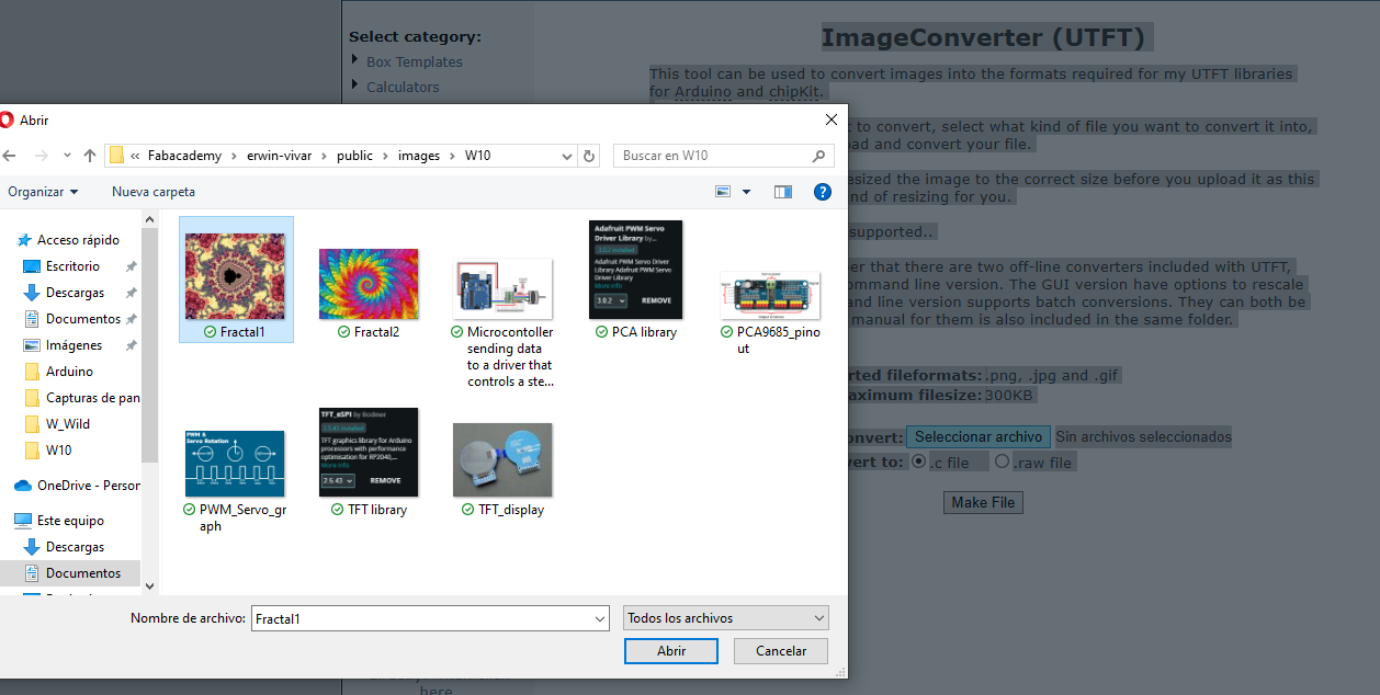
Before using the images in code, they need to be encoded. This is necessary because the microcontroller doesn’t understand image files—it works with bitmaps. To convert regular images into a format compatible with the TFT display, I used an online tool that transforms images into RGB bitmaps, which the TFT can interpret and display correctly


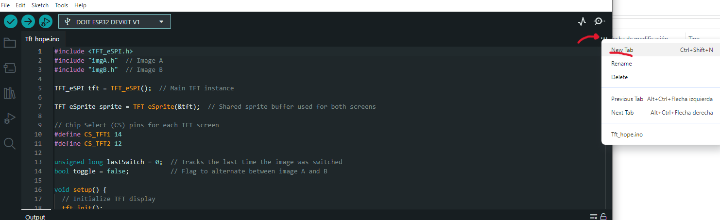
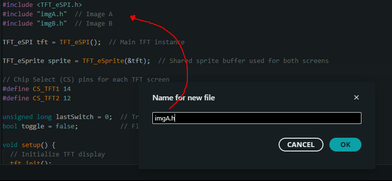
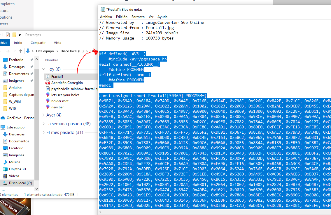
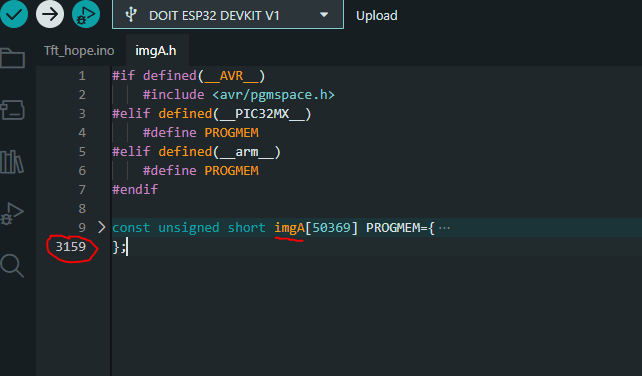
Once the conversion is done, here's the code I used:
  #include TFT_eSPI.h
  #include "imgA.h"  // Image A
  #include "imgB.h"  // Image B

  TFT_eSPI tft = TFT_eSPI();  // Main TFT instance

  TFT_eSprite sprite = TFT_eSprite(&tft);  // Shared sprite buffer used for both screens

  // Chip Select (CS) pins for each TFT screen
  #define CS_TFT1 14
  #define CS_TFT2 12

  unsigned long lastSwitch = 0;  // Tracks the last time the image was switched
  bool toggle = false;           // Flag to alternate between image A and B

  void setup() {
    // Initialize TFT display
    tft.init();
    tft.setRotation(1);       // Set screen rotation
    tft.setSwapBytes(true);   // Enable byte swapping for correct color rendering

    // Create a sprite with size 240x240 pixels
    sprite.createSprite(240, 240);
    sprite.setSwapBytes(true); // Enable byte swapping for the sprite as well

    // Configure CS pins as output and set them HIGH (inactive)
    pinMode(CS_TFT1, OUTPUT);
    pinMode(CS_TFT2, OUTPUT);
    digitalWrite(CS_TFT1, HIGH);
    digitalWrite(CS_TFT2, HIGH);
  }

  void loop() {
    unsigned long now = millis();

    // Switch image every 500 milliseconds
    if (now - lastSwitch >= 500) {
      lastSwitch = now;
      toggle = !toggle;  // Flip between true and false each time

      if (toggle) {
        // Load Image A into the sprite buffer
        sprite.pushImage(0, 0, 240, 240, imgA);

        // Draw Image A to TFT 1
        digitalWrite(CS_TFT1, LOW);   // Activate TFT 1
        tft.startWrite();
        sprite.pushSprite(0, 0);      // Push to screen
        tft.endWrite();
        digitalWrite(CS_TFT1, HIGH);  // Deactivate TFT 1

        // Load and draw Image B to TFT 2
        digitalWrite(CS_TFT2, LOW);   // Activate TFT 2
        tft.startWrite();
        sprite.pushImage(0, 0, 240, 240, imgB);  // Load Image B into sprite
        sprite.pushSprite(0, 0);      // Push to screen
        tft.endWrite();
        digitalWrite(CS_TFT2, HIGH);  // Deactivate TFT 2

      } else {
        // Load Image B into the sprite buffer
        sprite.pushImage(0, 0, 240, 240, imgB);

        // Draw Image B to TFT 1
        digitalWrite(CS_TFT1, LOW);   // Activate TFT 1
        tft.startWrite();
        sprite.pushSprite(0, 0);      // Push to screen
        tft.endWrite();
        digitalWrite(CS_TFT1, HIGH);  // Deactivate TFT 1

        // Load and draw Image A to TFT 2
        digitalWrite(CS_TFT2, LOW);   // Activate TFT 2
        tft.startWrite();
        sprite.pushImage(0, 0, 240, 240, imgA);  // Load Image A into sprite
        sprite.pushSprite(0, 0);      // Push to screen
        tft.endWrite();
        digitalWrite(CS_TFT2, HIGH);  // Deactivate TFT 2
      }
    }
  }
The code controls two TFT GC9A01 displays connected to an ESP32 using the TFT_eSPI library with only one instance for both displays. It alternates between displaying two images (imgA and imgB) on each screen every 500 milliseconds. A shared TFT_eSprite buffer is used to prepare the image before sending it to the screen, avoiding flicker. The chip select (CS) lines for each TFT are controlled manually through digital outputs (CS_TFT1 and CS_TFT2), allowing both screens to share the same SPI bus.
In the setup() function, the display and sprite are initialized, and the byte order is adjusted using setSwapBytes(true) to ensure correct color rendering for 16-bit images. Both CS pins are configured as outputs and set HIGH to keep both displays inactive until needed. The sprite is defined as a 240x240 pixel buffer, matching the resolution of the displays (this can be modified to resize the image shown on the display).
Inside the loop(), the code checks if 500 milliseconds have passed since the last switch. If so, it toggles the displayed content: one screen shows image A while the other shows image B, and vice versa on the next cycle. The images are first loaded into the sprite, then pushed to the corresponding display while its CS pin is pulled LOW (active), wrapped within startWrite() and endWrite() to ensure safe communication.
Power Consumption of TFT Displays
While testing the functionality, I also measured the current consumption of the TFT displays. The result was approximately 36 mA, measured using a multimeter connected in series between the power supply and the VCC/GND pins of the TFT. In this setup, the power source was my computer. This relatively low consumption suggests that these displays could be used in circuits powered by batteries rather than fixed supplies, which is ideal for my intended application.
PCA9685 Servo Control
Although it’s possible to manually control each servo by writing directly to their control registers and specifying precise PWM values, this approach becomes cumbersome when managing multiple servos. The point of this model is to simplify that task while also reducing the processing load on the microcontroller.
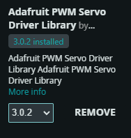
For this, I used the Adafruit_PWMServoDriver library. This library gives access to the control registers and allows PWM generation. However, it doesn’t automatically scale the PWM values based on angles or other units. To solve this, I created a function that allows setting the desired angle directly, translating it into the corresponding PWM signal.

  #include Wire.h
  #include Adafruit_PWMServoDriver.h

  // === PCA9685 Driver Initialization ===
  // Create an instance of the Adafruit PWM driver (PCA9685 chip)
  Adafruit_PWMServoDriver servos = Adafruit_PWMServoDriver();

  // === Servo PWM Boundaries ===
  // These values define the PWM range corresponding to 0° and 180° for a typical servo.
  // Adjust these if your servos require different pulse widths.
  const int pos0 = 102;    // PWM value for 0 degrees
  const int pos180 = 520;  // PWM value for 180 degrees

  // === Servo Channels ===
  // Array containing the PCA9685 channels where servos are connected
  const uint8_t servoPins[] = {0, 1, 2, 3, 4, 5};
  const uint8_t numServos = sizeof(servoPins) / sizeof(servoPins[0]); // Total number of servos

  // === Timing Control ===
  unsigned long lastUpdate = 0;          // Stores the last time the servos were updated
  const unsigned long interval = 500;    // Delay between updates (500 ms)

  // === Angle Tracking ===
  int baseAngle = 0;         // Starting angle for the first servo in the sequence
  bool increasing = true;    // Direction flag (true = forward, false = backward)

  // === Function to Move a Servo to a Given Angle ===
  // This function maps an angle (0–180°) to the PWM signal required by the PCA9685
  // and sets the corresponding servo to that position.
  void setServo(uint8_t n_servo, int angulo) {
    int duty = map(angulo, 0, 180, pos0, pos180); // Map angle to PWM
    servos.setPWM(n_servo, 0, duty);              // Send PWM signal to the servo
  }

  void setup() {
    Wire.begin();           // Initialize I2C communication
    servos.begin();         // Initialize PCA9685 driver
    servos.setPWMFreq(50);  // Set PWM frequency to 50 Hz (standard for servos)
    Serial.begin(115200);   // Initialize serial communication (optional for debug)
  }

  void loop() {
    unsigned long now = millis();  // Get current time

    // Update servo positions only every 500 ms
    if (now - lastUpdate >= interval) {
      lastUpdate = now;

      // Move each servo with a 30° offset from the previous one
      for (uint8_t i = 0; i < numServos; i++) {
        int angle = baseAngle + (i * 30);       // Add 30° offset per servo
        angle = constrain(angle, 0, 180);       // Limit angle to valid servo range
        setServo(servoPins[i], angle);          // Move servo to calculated angle
      }

      // Adjust the baseAngle for next cycle (oscillating movement)
      if (increasing) {
        baseAngle += 10;
        // If maximum reach is exceeded, reverse direction
        if (baseAngle + (numServos - 1) * 30 >= 180) {
          increasing = false;
        }
      } else {
        baseAngle -= 10;
        // If minimum reach is exceeded, reverse direction
        if (baseAngle <= 0) {
          increasing = true;
        }
      }
    }
  }
The program starts by including the required libraries: `Wire.h` for I2C communication and `Adafruit_PWMServoDriver.h` to control the PCA9685 chip, which allows driving multiple servos via PWM. A driver instance (`servos`) is declared, followed by constants that define the PWM values corresponding to 0° and 180° servo angles. An array `servoPins` lists the PCA9685 channels used (from 0 to 5), and `numServos` dynamically calculates the number of servos. Timing and direction variables (`lastUpdate`, `interval`, `baseAngle`, and `increasing`) are declared to manage the oscillating movement logic.
The `setServo()` function maps an angle (0–180°) to its corresponding 12-bit PWM value using `map()` and sends this signal to the specified channel via `servos.setPWM()`. The `setup()` function initializes I2C communication with `Wire.begin()`, starts the PCA9685 driver with `servos.begin()`, sets the PWM frequency to 50 Hz (standard for servos), and begins serial communication for debugging. These steps prepare the system to deliver clean, reliable PWM signals to all connected servos.
Inside the `loop()`, the program checks if 500 ms have passed since the last update. If true, it loops through each servo, calculating a target angle with a 30° offset between them and applying this angle using the `setServo()` function. The result is a staggered sweeping motion. The direction of the base angle alternates using the `increasing` flag: it increments until it would exceed the max valid range, then reverses and decrements until it reaches zero. This creates a back-and-forth oscillation that moves all servos in a coordinated wave pattern.
Power Consumption of Servos
In this case, I measured the current using the power source readout. However, the consumption can’t be generalized, since it depends on the motor’s characteristics and the torque required at any given moment. For example, even a small SG90 servo may consume between 100 mA and 200 mA, especially under load.
When dealing with high-torque servos—e.g., 20 kg·cm models—the situation changes drastically. These can draw up to 3 A when facing resistance. This is a critical factor to consider in my final project. Mechanical components must allow smooth movement with minimal friction to reduce torque demands.
A major advantage is that the PCA9685 isolates the control logic from the motor power circuit. So, if a servo draws excessive current, it won’t damage the microcontroller or the rest of the logic circuit. At most, the module itself could be affected, but it is designed to handle high loads safely.
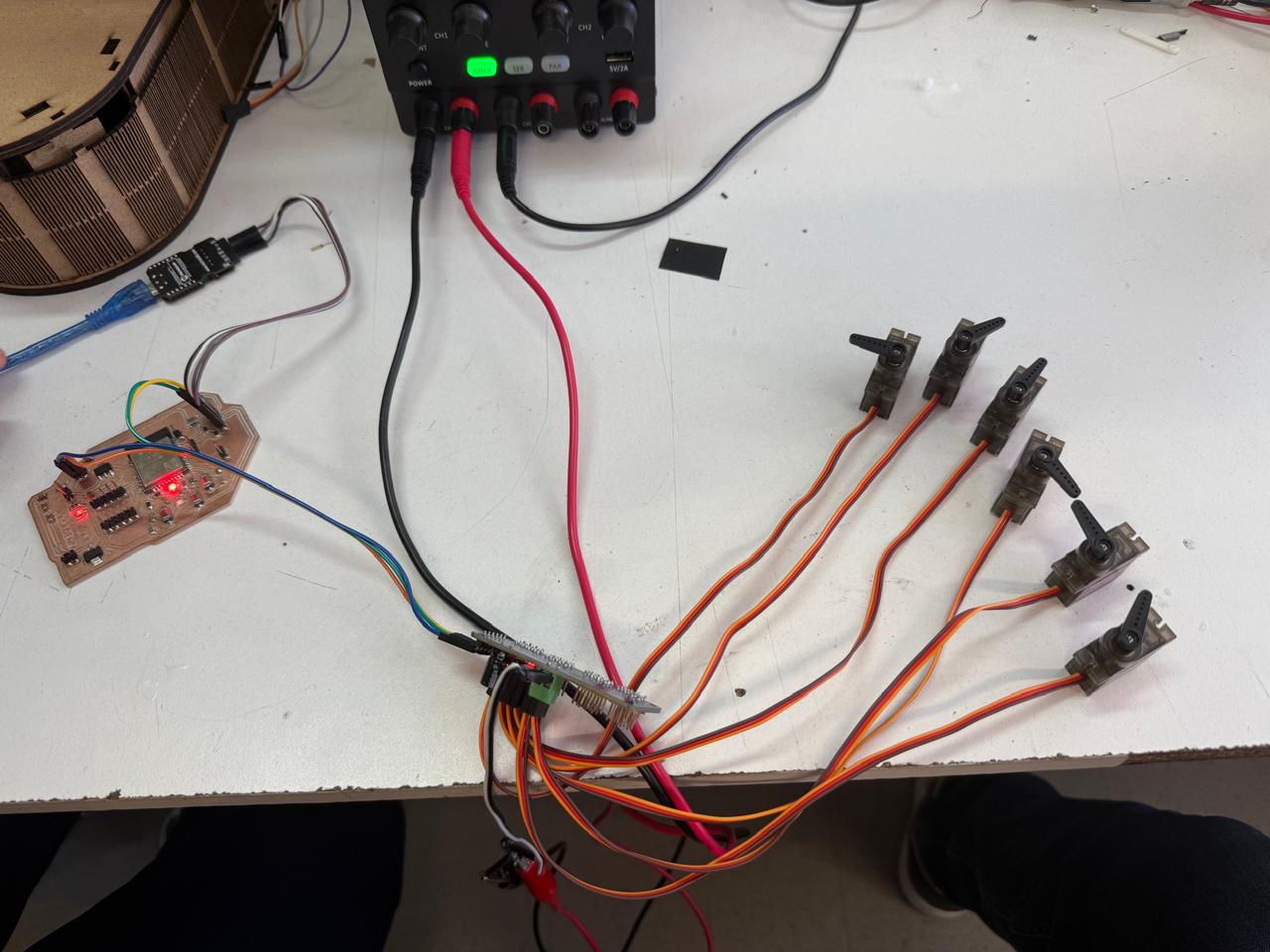
HEROSHOT! MASTER SERVO.
LEARNINGS
This week offered a wide range of learnings. Most digital output concepts—such as generating a logical HIGH or LOW, or configuring PWM for servos—were relatively straightforward for me thanks to prior experience and coursework.
What did present a challenge was learning to control TFT displays. I had never worked with this type of screen before. My past experience involved LCDs or OLED displays, both of which rely on entirely different communication protocols, such as I2C.
Understanding SPI communication, required by TFTs, was entirely new to me. This also helped me understand why these displays are rarely used in university labs: they demand significant memory and processing resources. Unlike black-and-white displays, a full-color bitmap is much heavier and resource-intensive.
Because of this, many TFT setups rely on SD cards to store images and offload that burden from the microcontroller. While that’s something I’ll keep in mind for future applications, it won’t be critical for my current project, since the animated eyes in my animatronic design will not require a large number of stored images.