2. Computer Aided Design
This week's assignment tasks are listed below:
- Model (raster, vector, 2D, 3D, render, animate, simulate, ...) a possible final project.
- Compress your images and videos
- Post a description with your design files on your class page.
2.1. Model (raster, vector, 2D, 3D, render, animate, simulate, ...) a possible final project.
2D Images: Raster & Vector Images
Raster Images
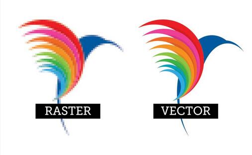
Raster images are made by many pixels which are the smallest addressable elements of a raster images. Each pixel emits a specific color by mixing different ratios of red, green, & blue (RGB).
Source: Additive and Subtractive Colour Theory, Universal Paints
Vector Images
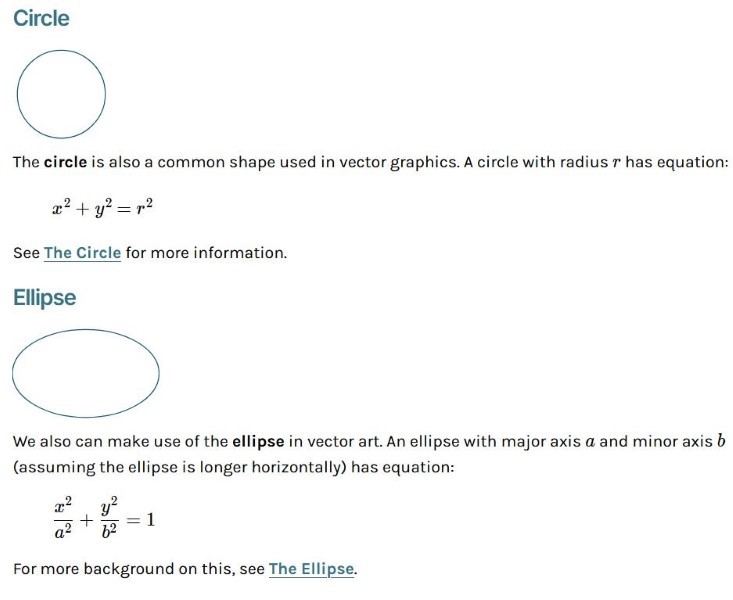
Source: Mathematics of Vector Art, Interactive Mathematics
Vector images are made by saving data as mathematical equations that create a particular shape, which means there are no specific pixels and the equations can be multiplied to scale without any loss in quality.
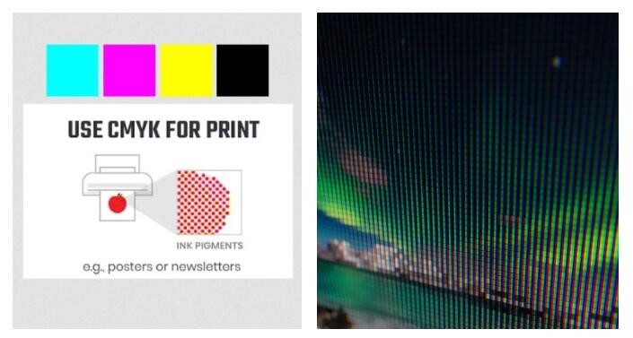
Applications of Vector and Raster Images
Raster images are used in printers and display devices. Hence, vector images need to be converted to raster images before being printed or displayed.
Source: Additive and Subtractive Colour Theory, Universal Paints
LCD Screen Shader, Blend Swap
Vector images are used for digital illustrations like logos that are to be used in different sizes and formats.

Source: India Today, Fortune India, Tech in Asia
Creating a 2D Raster Image using PhotoPea
Step 1: Generating concept ideas using AI
I used Whatsapp Meta AI to generate images
Finally I settled on this image
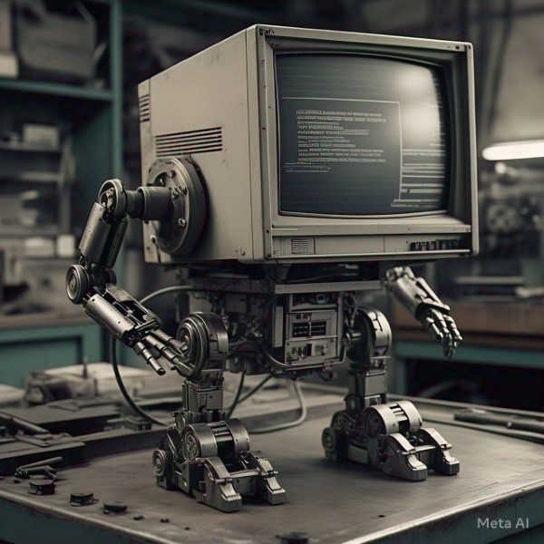
Prompt: Generate an image of old computer without keyboard with robot legs
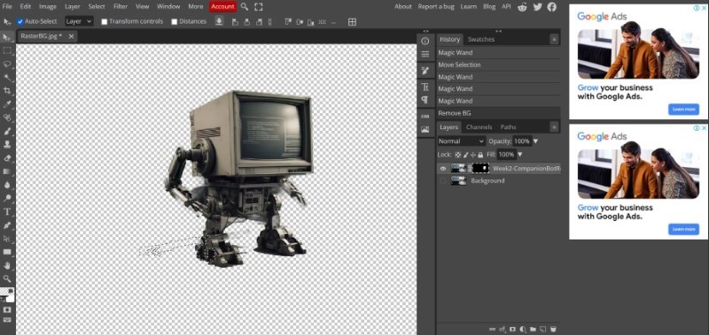
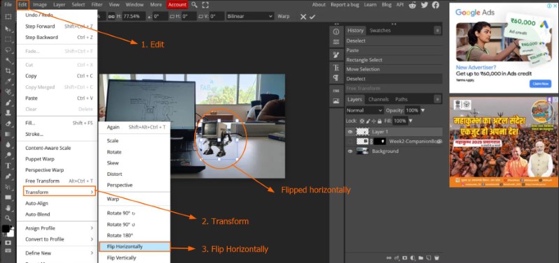
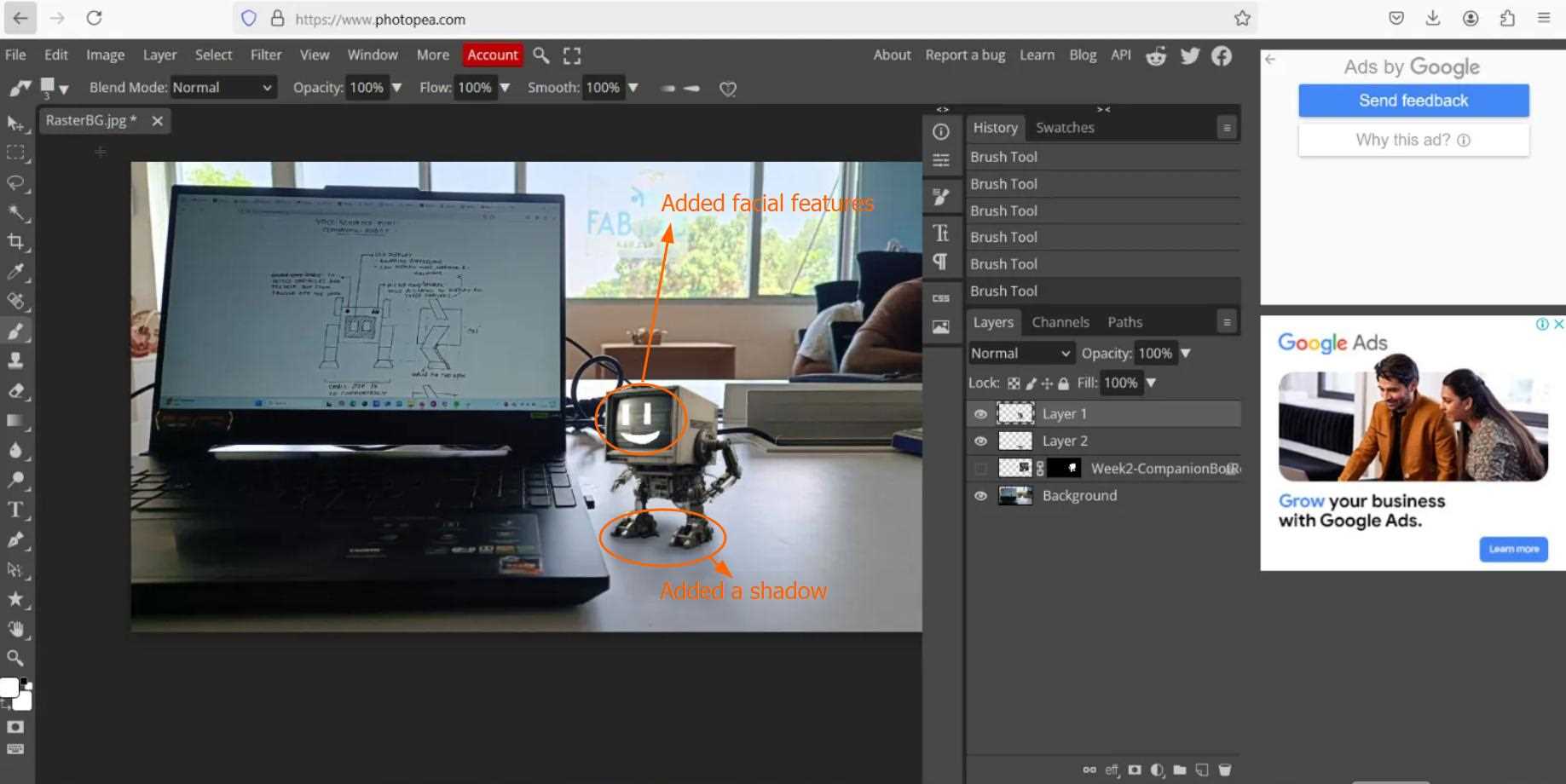
Step 2: Editing the image in Photopea
I was able to remove the background of this image in just two clicks, which was a pleasent surprise
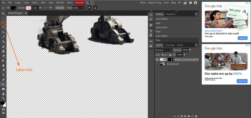
I only had to make minimal corrections in areas where it was too dark for the software to figure out the edge of the subject and the background, which I zoomed in by pressing Middle Button (Scroll Wheel) and removed manually using a lasso tool.
I used a Youtube tutorial to figure out a shortcut Ctrl+Alt+T to move, scale or position a layer.
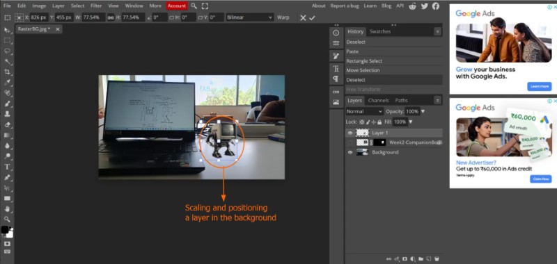
I flipped the image horizontally because it felt more aesthetic that way.
Used Brush, Erase & Blur tool in a new layer to add a shadow and facial details.
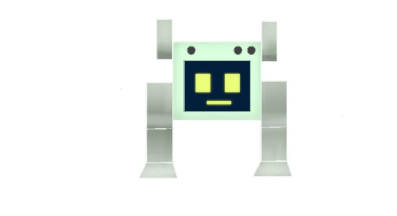
This is the end result
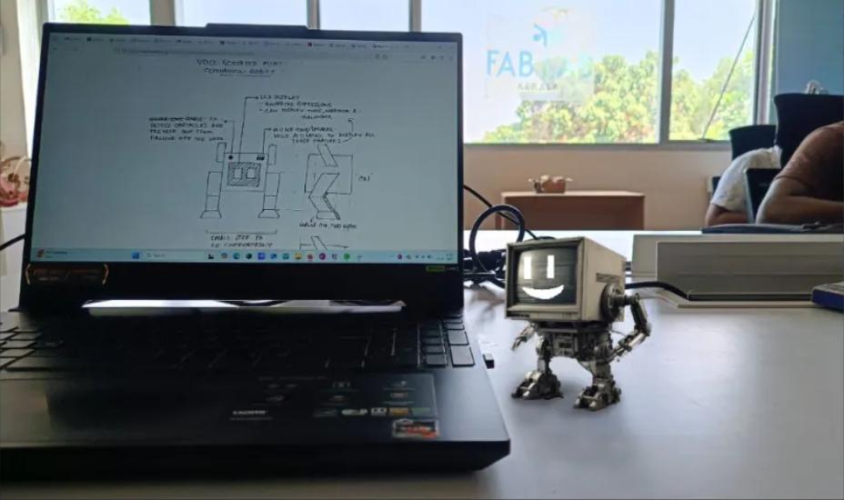
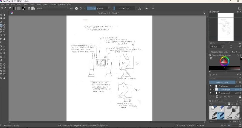
Creating a 2D Raster Image using Krita
I will be making a colouring of my concept using my original sketch as reference.
First, I imported my reference sketch into Krita.
In order to learn to use Krita, I used the help of this tutorial. Each part was drawn in a seperate layer, which allowed me to duplicate layers (for eg: the leg or the ear) and get an identical copy which can be positioned at the other side of the robot. Once all the line art was made I merged all the layers to a layer renamed as 'Line Art'.
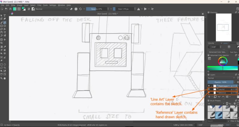
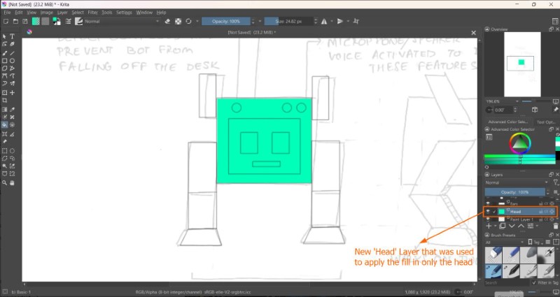
To add a fill to a layer I first added a paint layer below the sketch layer (Head layer etc.) Then I selected the sketch layer and then click inside the area you want filled.
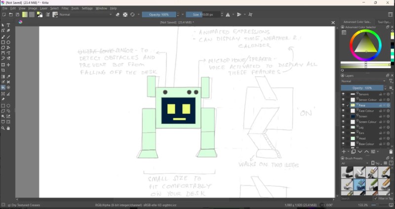
Here I have added a base colour to all the components.
Once the basic colours were added, its now time for fine adjustments. I added Gaussian blur to the facial features of the robot using Gaussian blur feature. I used a mix of two different brushes; Basic-1 and Blender Blur at different opacities and sizes to achieve a digital water colour painting of my concept.
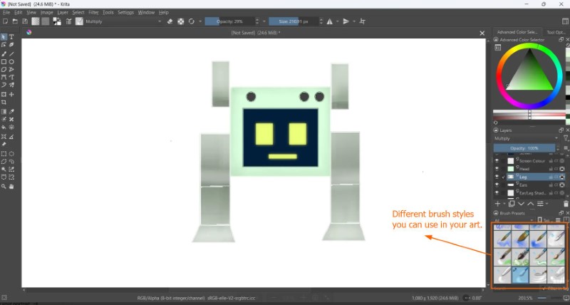
Here is the final result:
Creating a 2D Vector Image using Inkscape
Inkscape is a free vector graphics editor. To download Inkscape click here
Idea generation
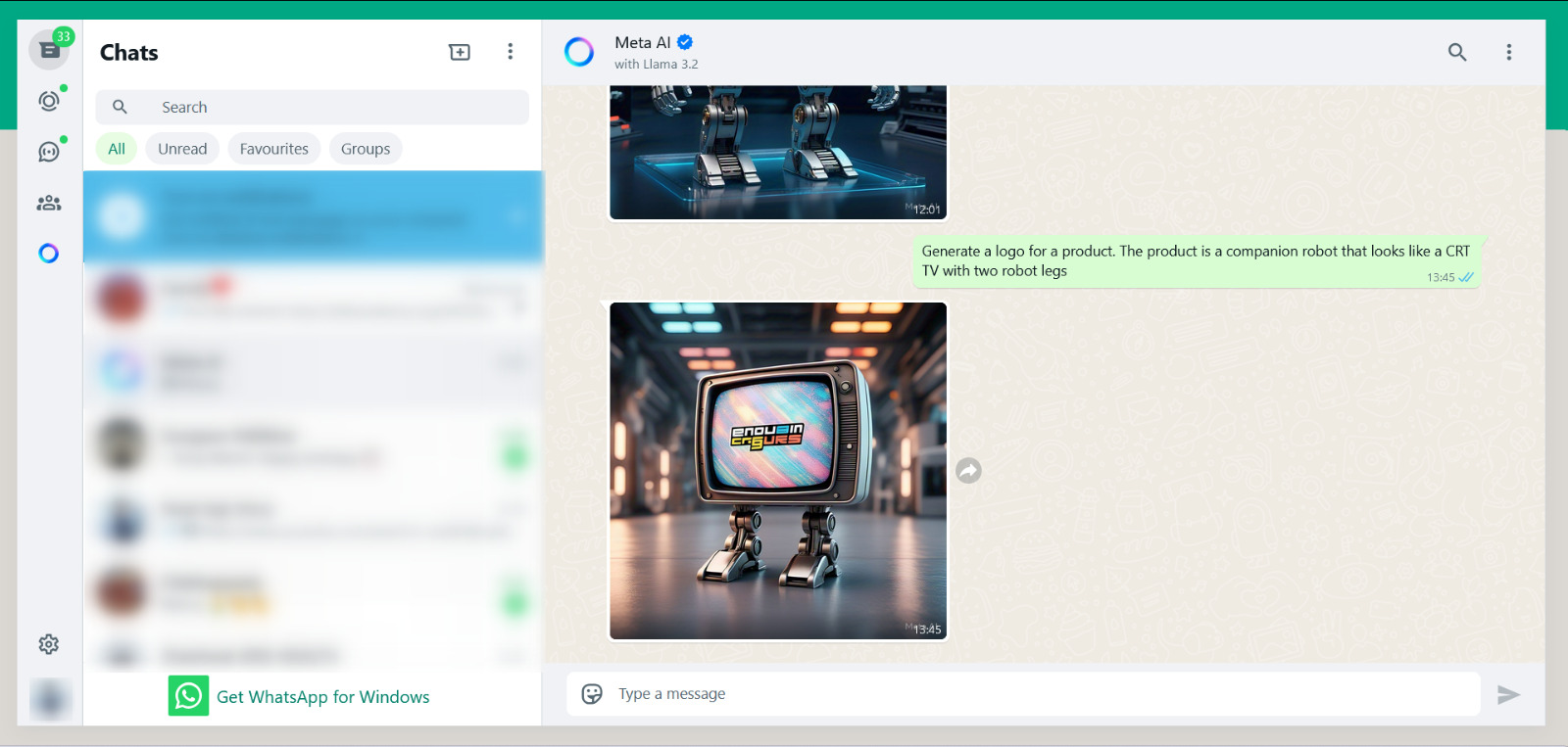
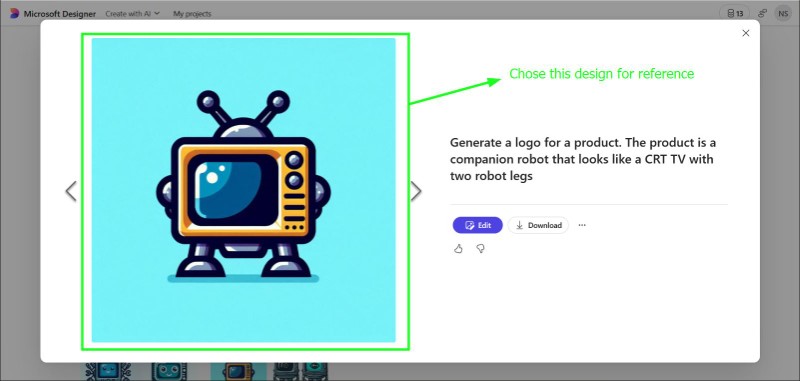
I experimented with generating logos using different browser-based based AI software. Meta AI (in Whatsapp), Microsoft Designer and Canva's AI image generator
Prompt: Create a logo for the following product: A companion robot in the shape of a CRT TV with robot legs
Prompt: Generate a logo for a product. The product is a companion robot that looks like a CRT TV with two robot legs
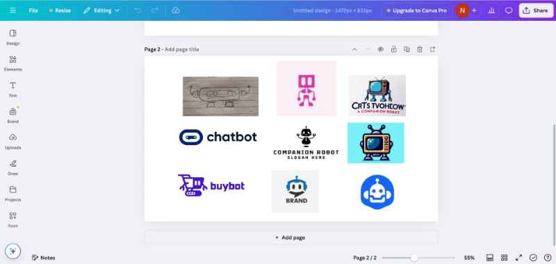
Apart from this I went on Google and found inspiration, and even made a sketch of a possible logo. All these images were combined into one file in Canva
Sources:
30 Best Robot Logo Design Ideas You Should Check, Kreafolk
A simple robot logo made by agustriana289
Andromeda Robotics
Design.com
Microsoft Designer (AI)
Canva AI image generator (AI)
Creating a logo for my final project in Inkscape

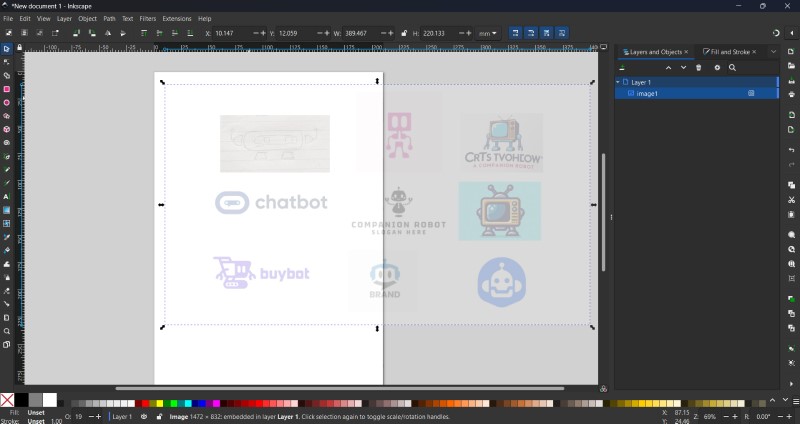
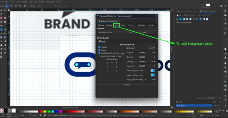
I imported the reference design file into Inkscape. I then resized the canvas size using Ctrl+Shift+D shortcut that I found from this article. I then added a grid using this tutorial.
I then made an outer sketch of the reference design. For this I first tried using the Bezier/Pen and Node tool
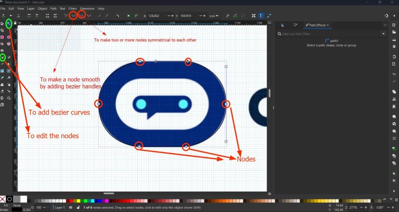
But I found it very hard to manipulate it in a symmetric manner, so instead I used the ellipse tool to create 2 ellipses and centered them manually. Then I added a third triangle
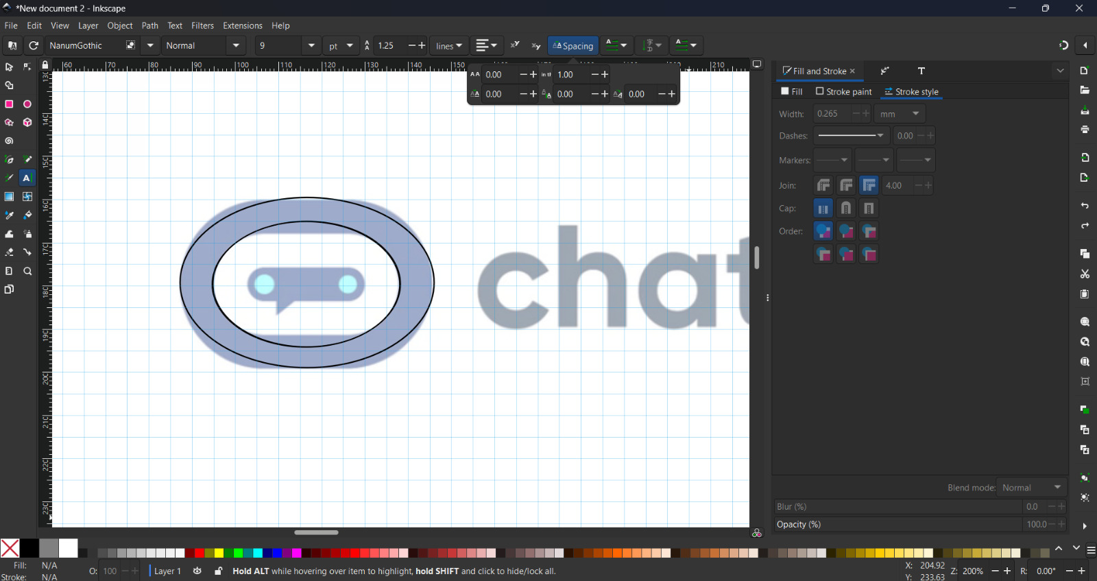
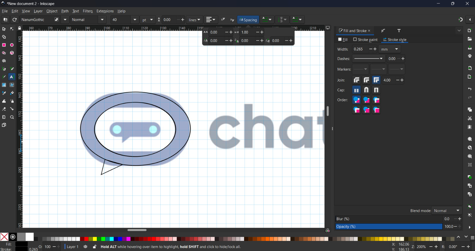
I then combined any intersecting shapes using the Union operation.
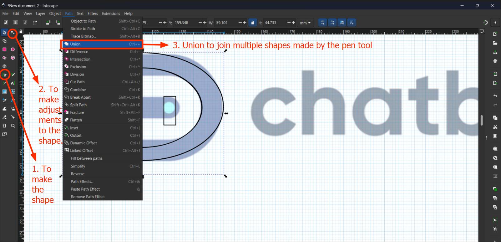
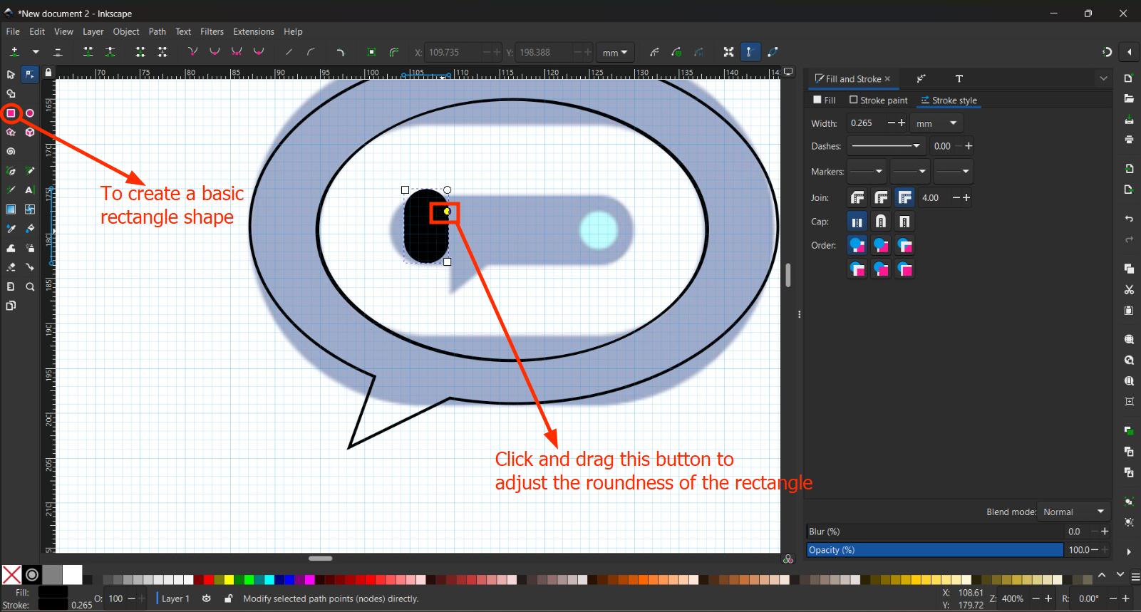
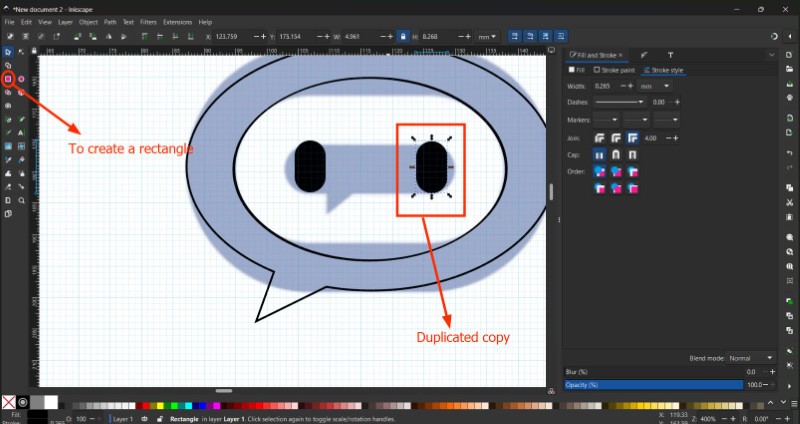
For the eyes, I added a solid rectangle, rounded it and duplicated for the second eye.
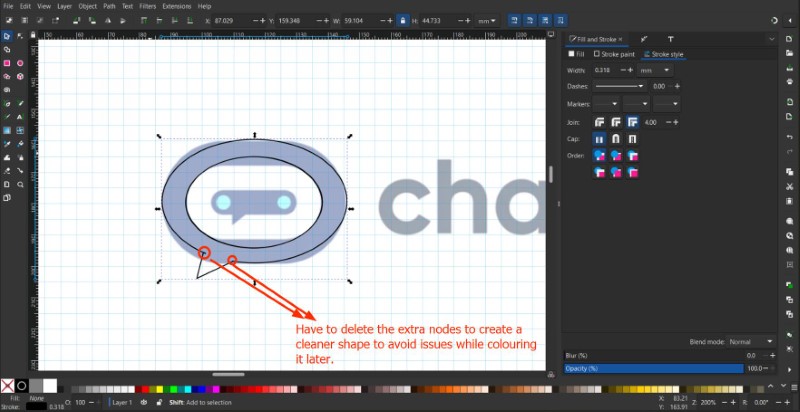
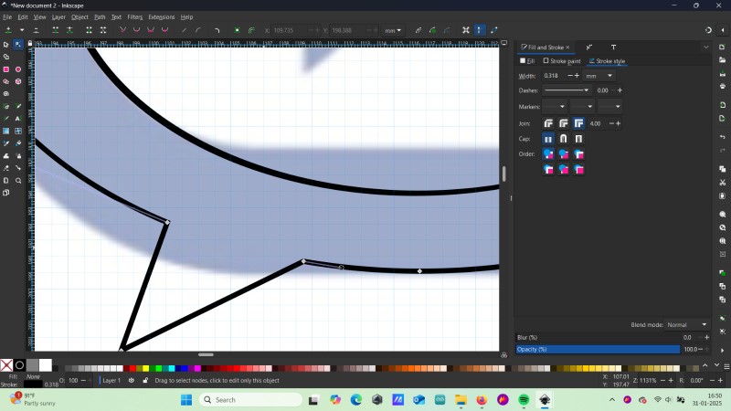
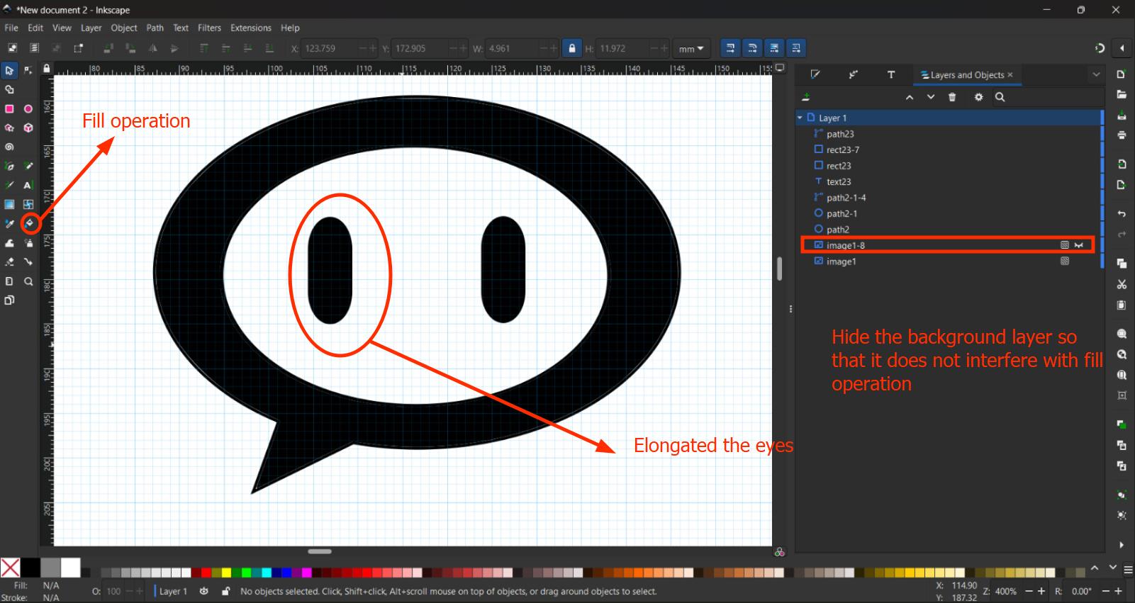
I then added a black colour fill inside the shape after hiding the reference layer to remove any potential interference. I also elongated the eyes a bit further to make it look more like actual eyes.
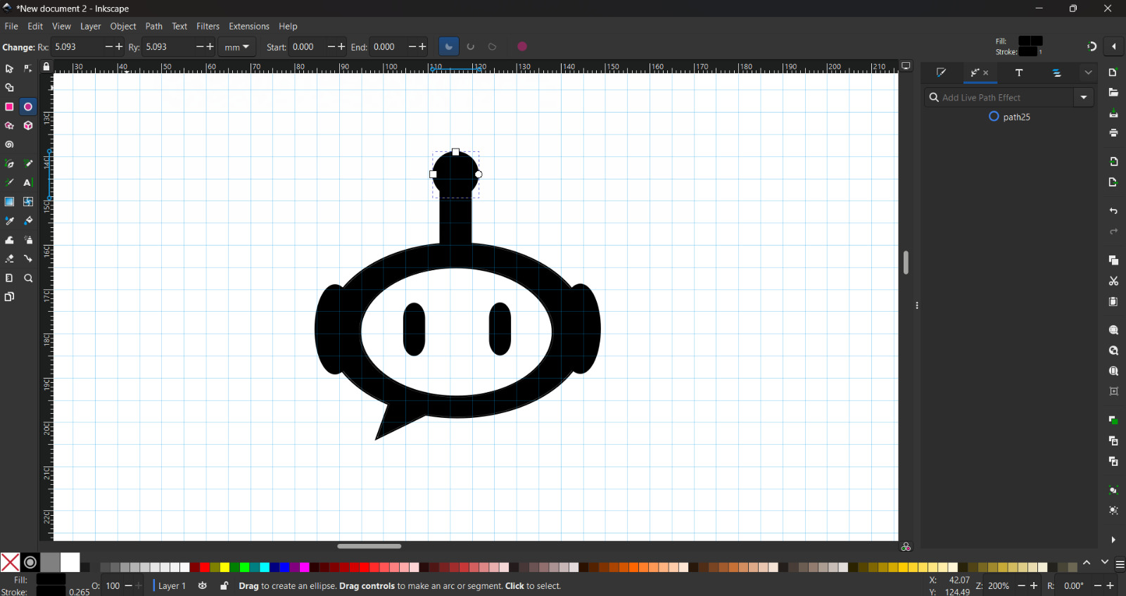
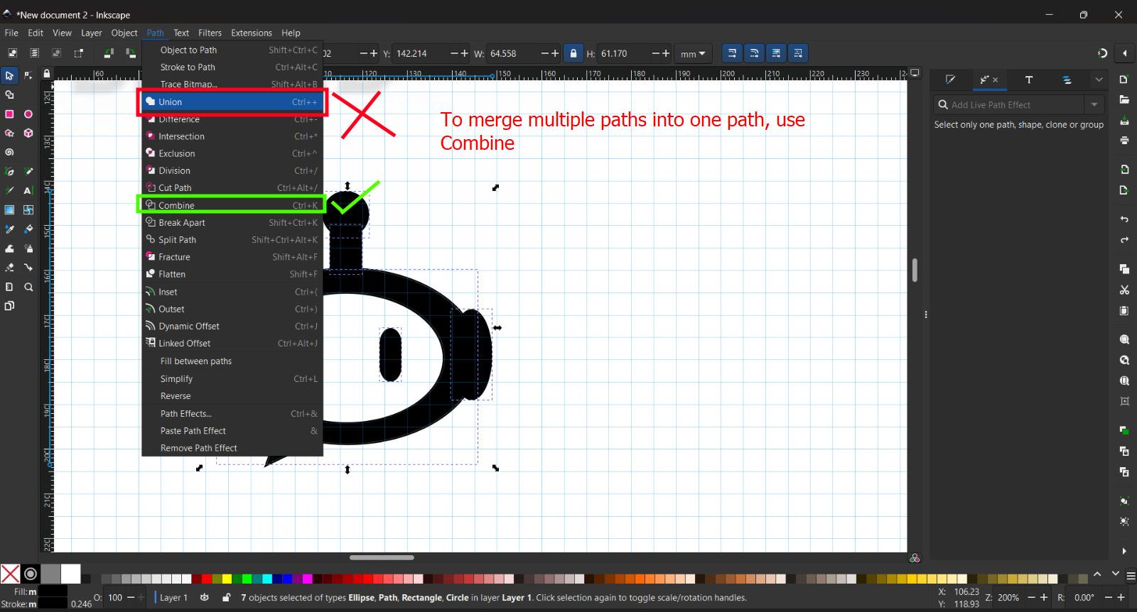
I then added ears and an antenna using the ellipse and circle tool. Press Ctrl while dragging to create a perfect circle. Later I shortened the rectangle path of the antenna. To merge the paths, I first tried using Union but it will not work since it is used to merge two intersecting shapes which is not the case here. Instead we use the Combine operation.
Now we add some text to our graphic. To do that press 'T' anywhere in the workspace. To generate potential product names I used the following AI Prompt (Chat GPT):
Prompt: Generate product names for a companion robot that will answer your questionsTo curve our text around the picture I first made a circle. which I then aligned in such a way that the center of the circle falls somehwhere in the center of the graphic.
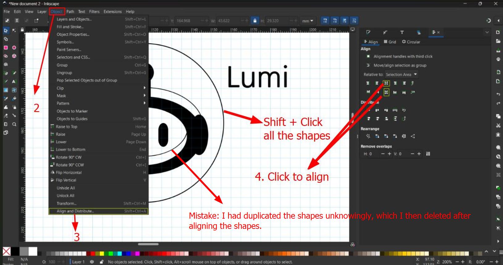
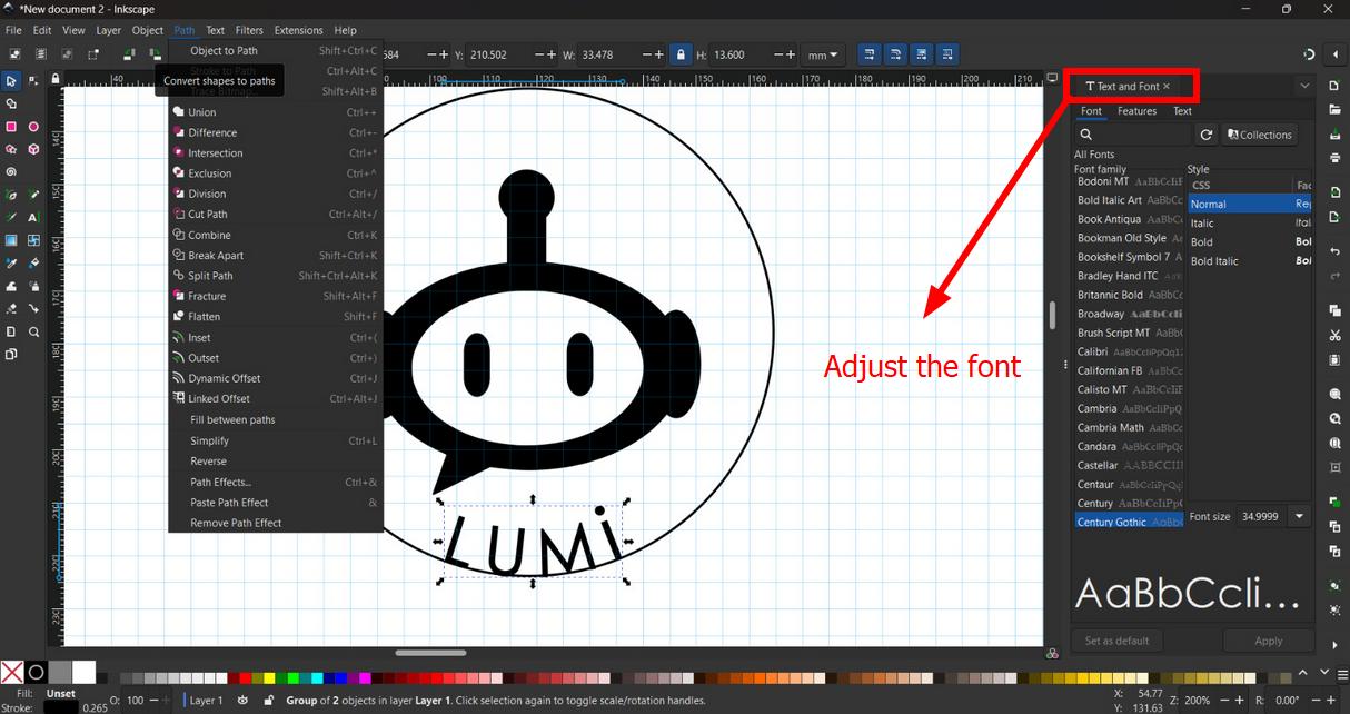
Then I placed the text on the circle path using 'Put on Path' operation. I adjusted the text so that it is is positioned at the bottom of the circle. I also changed the text font and size accordingly. Once the position has been finalised, I select the text and select Object to Path command. Now I can delete the circle and the text will remain in place.
Once done, I scaled the logo to match the size of the canvas and aligned it to the center of the page.
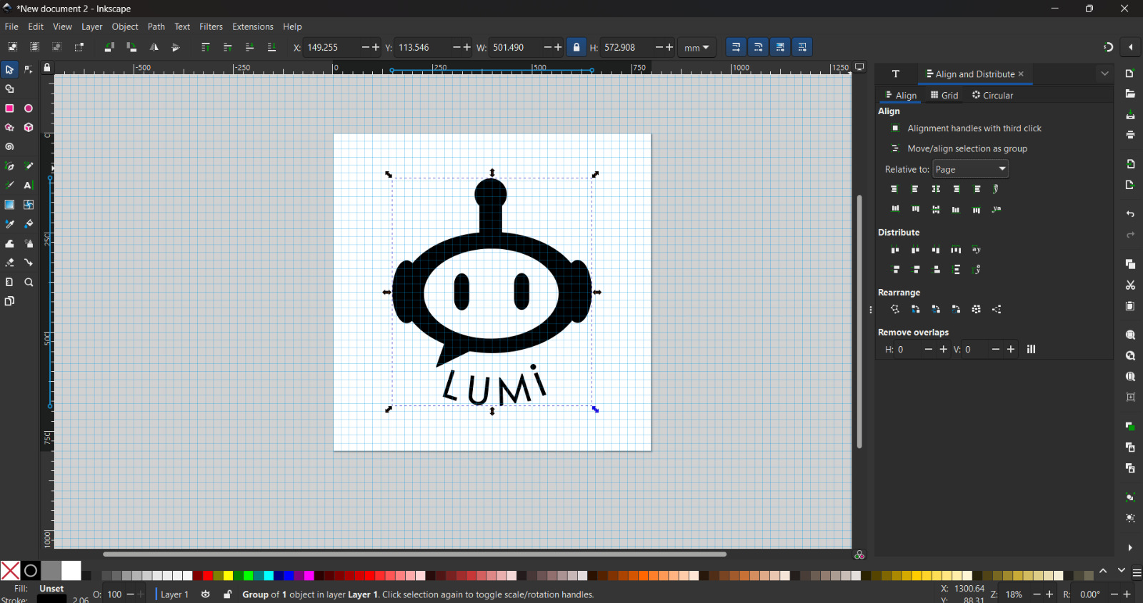
This is what the final result looks like:
Creating a 3D Model using Fusion
Fusion is a paid CAD software made by Autodesk for makers and hobbyists. It also offers a 30 day free trial with full access to its features and a free limited version for hobbyist users.
You can download Fusion by clicking here.
Creating the CRT monitor body
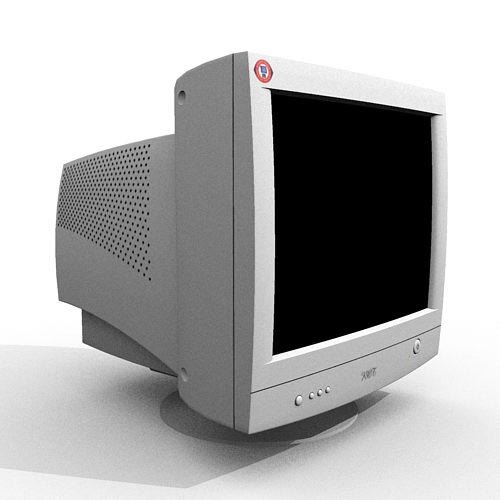
For references I searched for 3D models of CRT TV monitors. I chose this specific model as reference. I took screenshots of right, front, left and right views which I then impported into Fusion. In hindsight, only the front one side view was required.
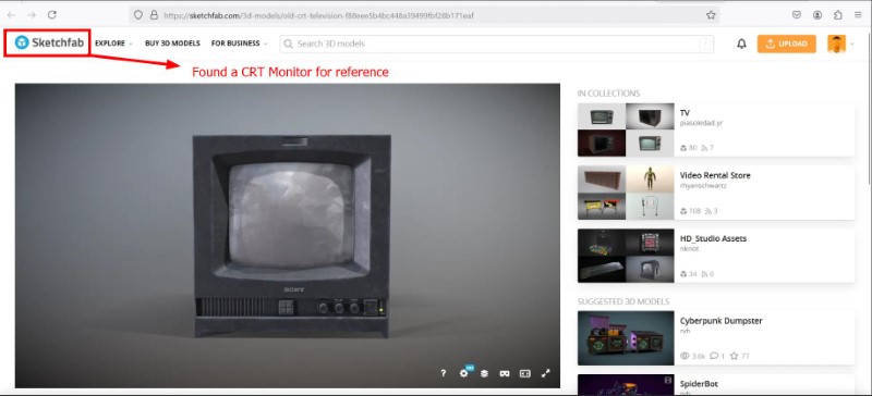
Source: Old CRT television, Sousinho
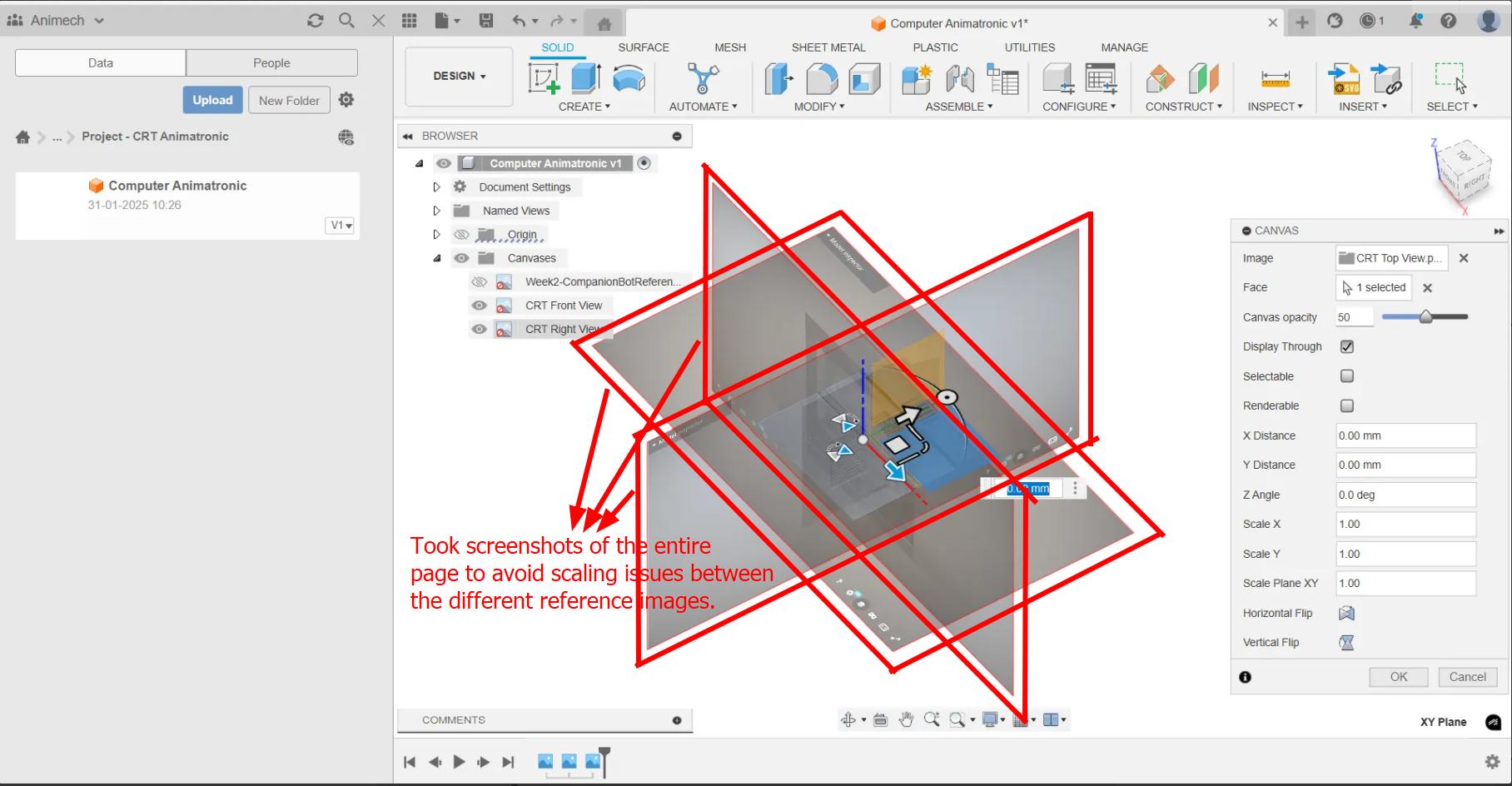
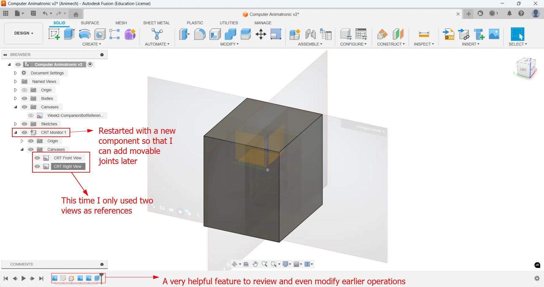
I took screenshots and added them as canvases in different orientations. I took screenshots of the entire screen each time to avoid scaling issues. I then used the front view as reference and made a sketch which I extruded to make the cuboid.
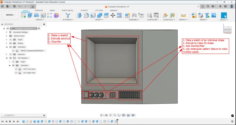
To make the LCD screen, I used the Extrude (Cut) feature and Chamfer operations. To make the knobs and ridges below the screen, I sketched the 2D shape and extrude (join) operation to make one of each of the features. Then I made copies of them using the Rectangular Pattern operation and smoothed out the hard edges using Fillet or Chamfer operation. In this way I made the body of my companion robot.
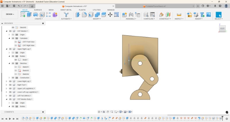
Making the legs of the robot
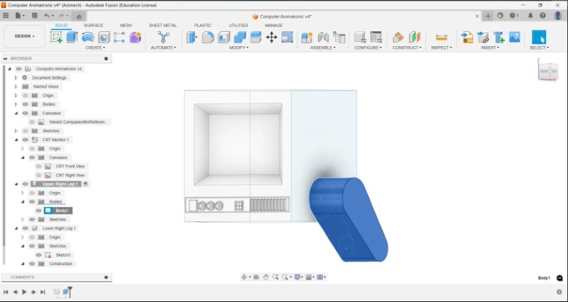
First, I make a new component, and then I made a sketch using the side face of the robot as reference. I then extruded it to make the outer body of the upper leg.
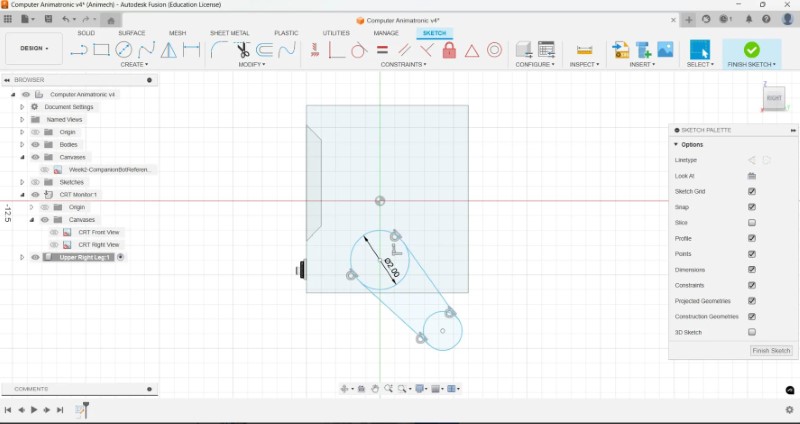
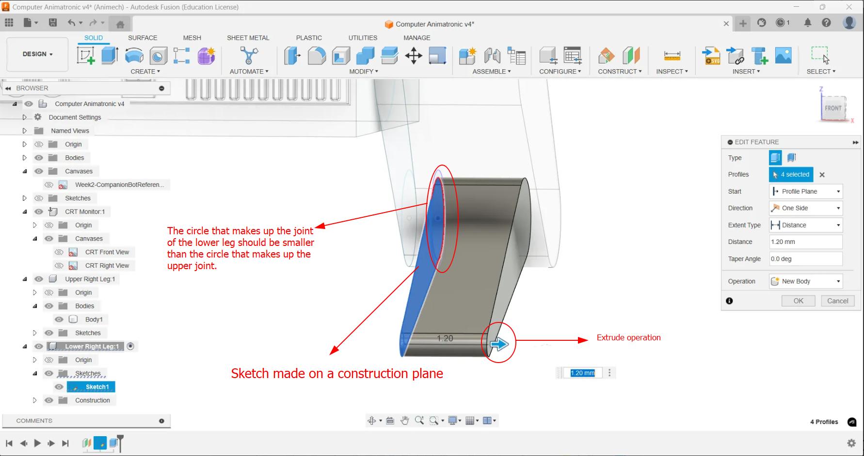
Now I have to make the lower leg fit inside the upper leg. To start with I made a new component, and then added a construction plane slightly offset to the inside of the upper leg. To be able to better manipulate the sketch, I hid the body of the upper leg. The cylinder of the hinge joint of the lower leg will be slightly smaller to fit inside the upper leg. It is important that the lines that make up the frame of the leg are tangent to the circle.
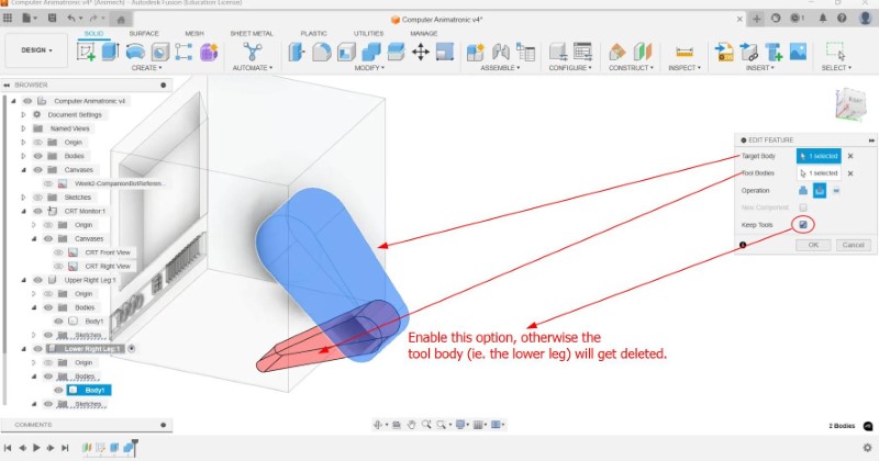
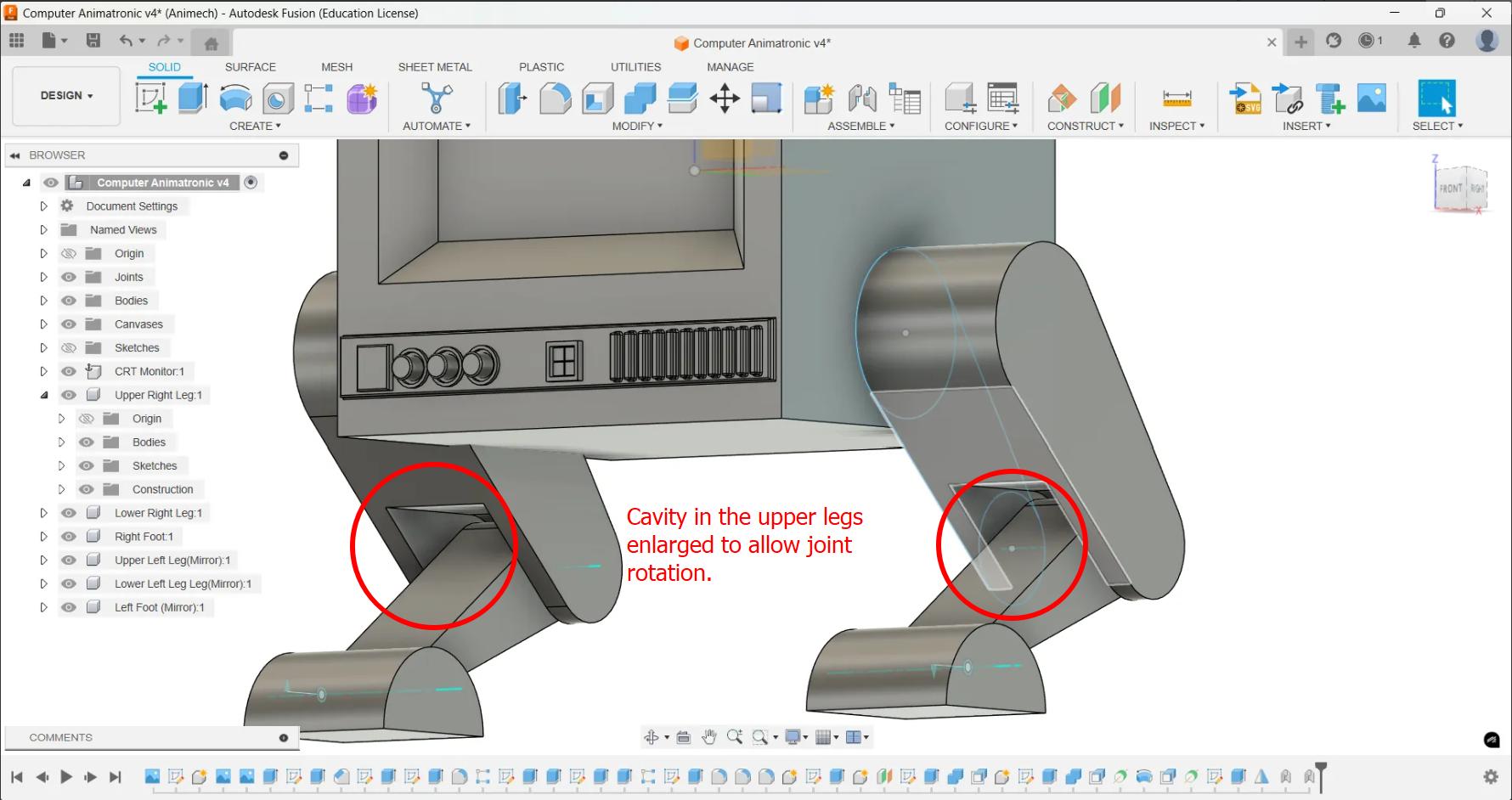
To make the cavity in the upper leg that houses the inner leg joint, I selected the upper leg component and used the combine operation with the upper leg selected as the target body and inner leg being selected as the tool body. Offset faces tool was used to make the cavity slightly bigger.
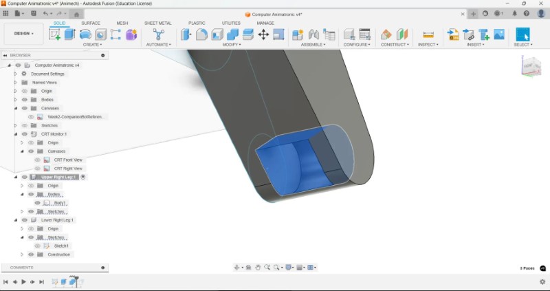
Note: Ensure that you check the keep tools option in the combine feature so that the the lower leg does not get deleted like I had done by mistake.
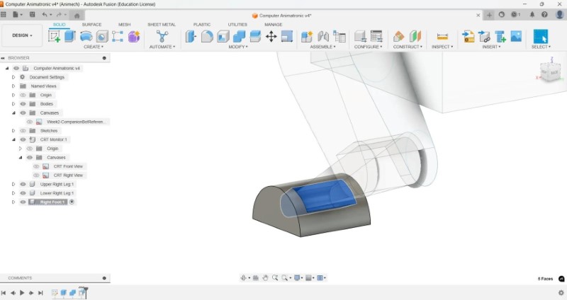
It is only when modeling did I realize that the feet will require a hinge joint also, so I made new component and added a sketch of right foot. I extruded the shape to the same width as the upper leg, then repeated the combine and offset faces operations to create a cavity for the lower leg to sit in.
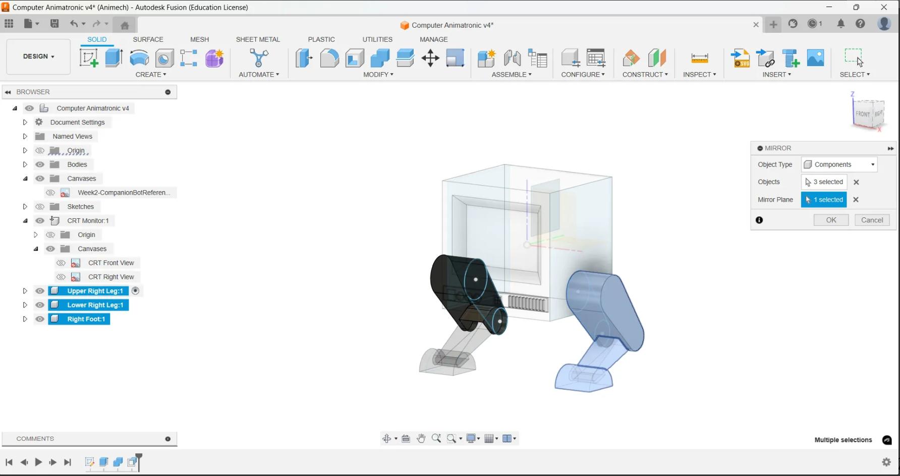
I then created a Mirror copy on the other side and renamed the compoennts on the left side
Adding joint movements to our model
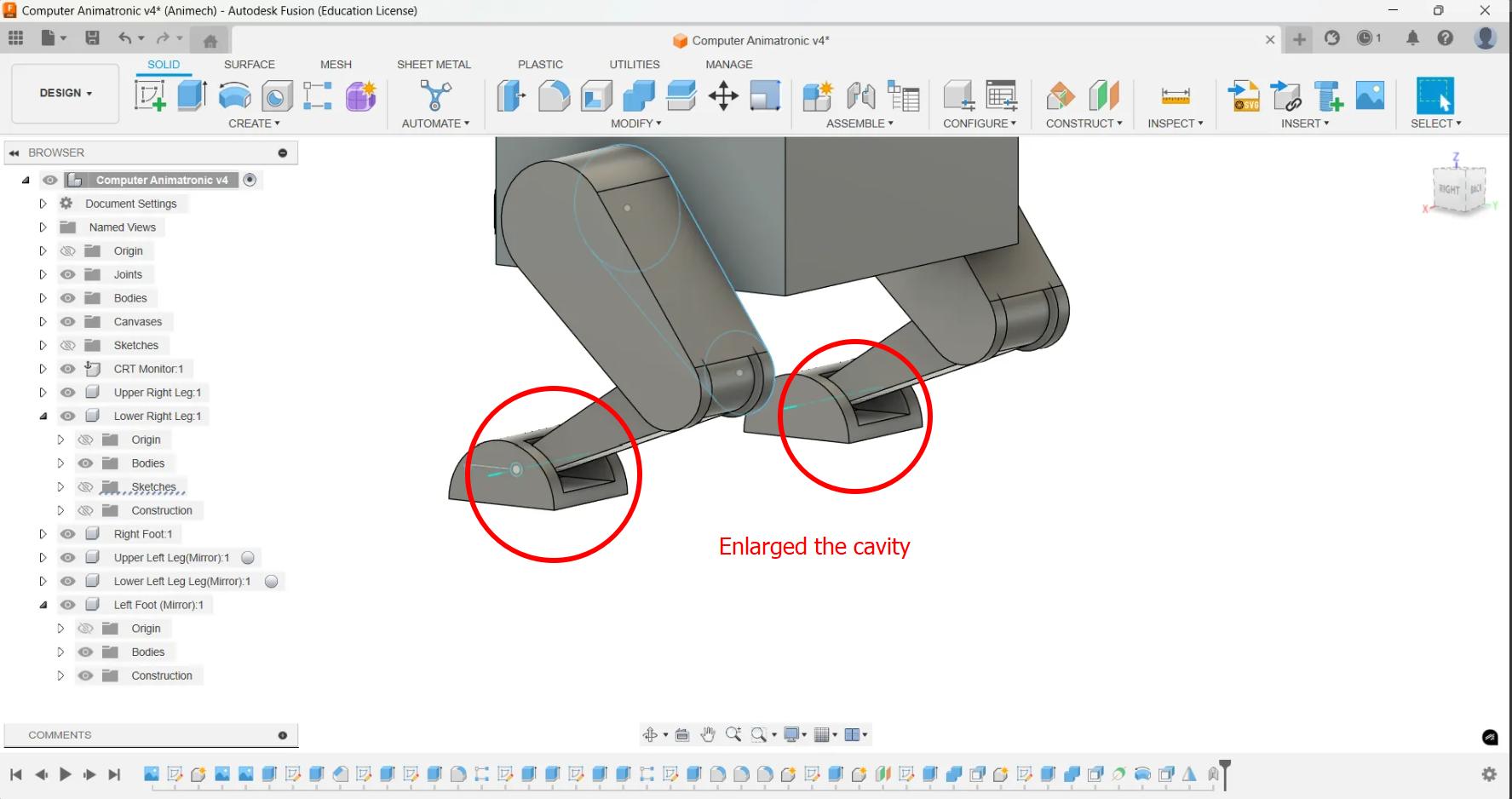
While constructing the joints, I realized that the cavity in the foot and the upper leg should be larger to accommodate for the joint rotation. I used different methods to enlarge the cavity. The change was reflected in the mirror copy because the operation is registered as done before.
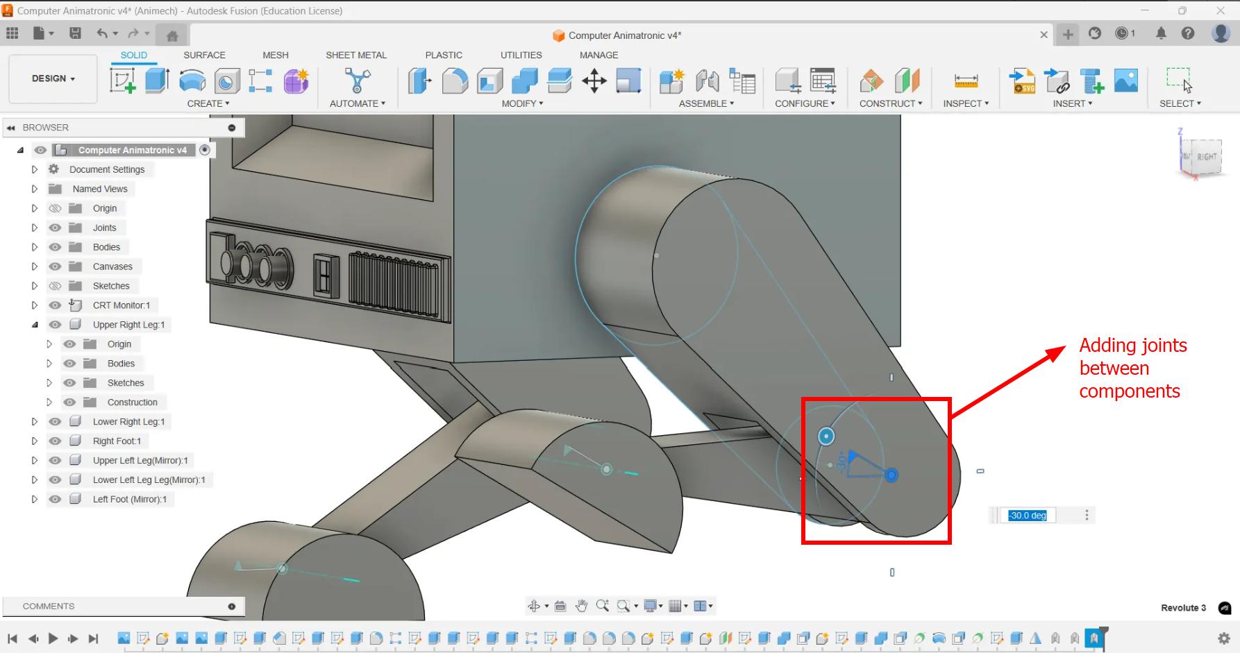
I then added joints to be able to move each components.
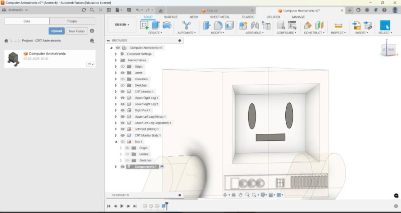
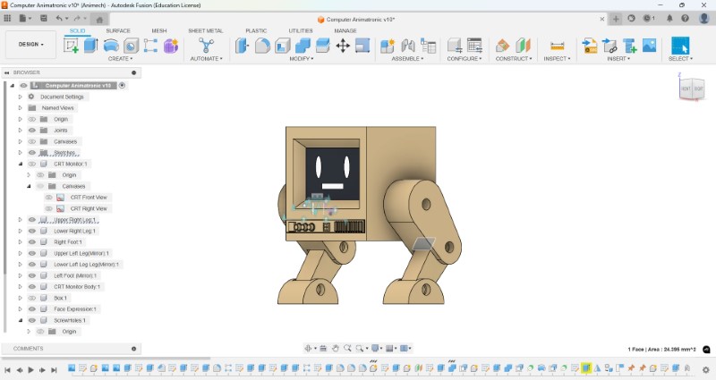
I then added facial features and textures to the components.
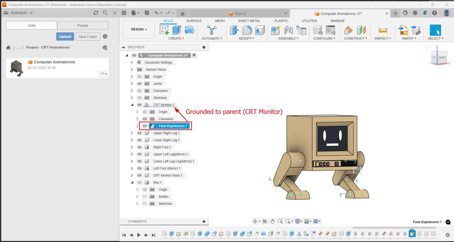
Final Output
I then simulated the joint relationships and took a screenrecording of it
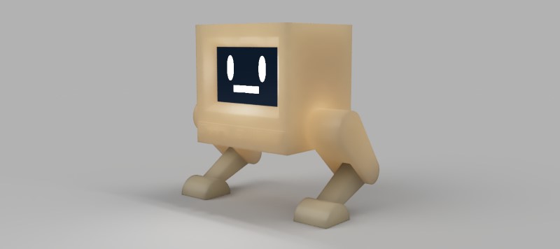
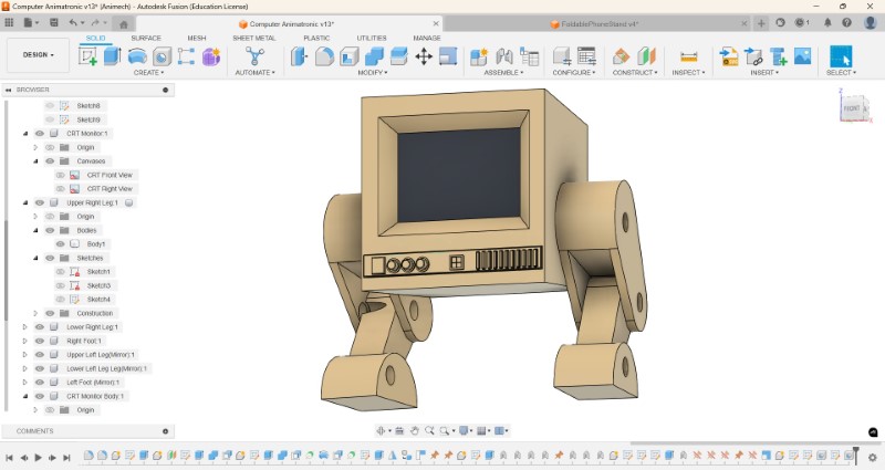
This is model when rendered as a still image.
This is the model when rendered as a turntable.
Make an action figure of Lumi, my CRT animatronic robot
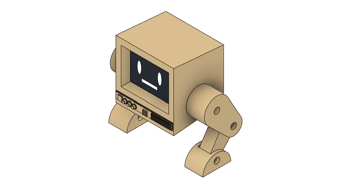
23-02-2025: I wanted to make a poseable action figure model of my final project, so I started with the 3D model I had made during Week 2 (CAD Design). All I have to do this model to make it print ready is:
- Scale it down to required size
- Make holes for screws in three joints
- Improve the look of the CRT animatronic
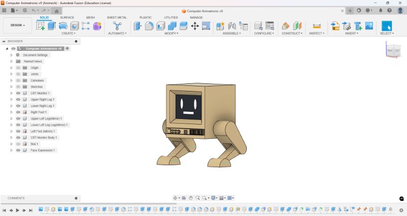
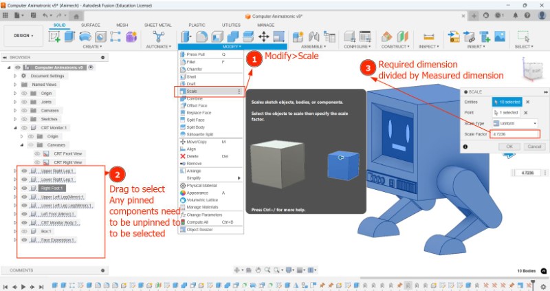
I saw that model was actually very small because the face CRT body was only ~6x6 mm, which is too small. I used this tutorial to learn to scale multiple components. Also, you have to unpin an pinned objects like I did (to be able to create the joint relationships seen in Week 2
Now to create the holes for the threads I used this video from Slant 3D and Fischer 3Dto make holes on which I will use my screws to remove material to create the threads
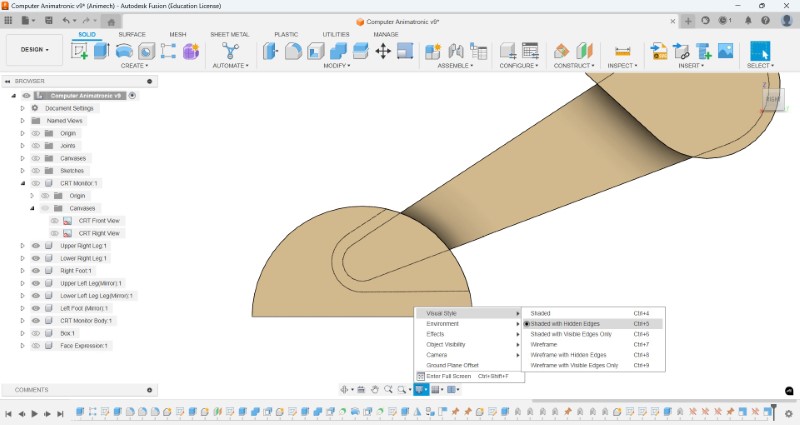
First I enabled Hidden edges in Viewstyle to be able to see the internal shapes of the joints
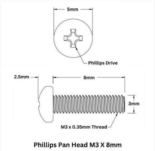
I used a M3 X 8mm Phillips Pan head as reference for dimensions
As you can see the hole was a bit larger than the end of the leg, so this needs to be readjusted using either
- reducing screw size (eg: M2)
- Or increasing width of the leg at the end
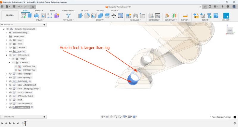
I tried reducing the screw size without any sucess. Now my only option is to increase the leg width
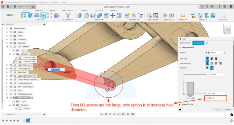
Since the sketch was made much before the scaling operation, I cannot simply add 10 mm based on current requirements
To make it all adjustable with different screwhole sizes, I parametrized the dimensions of the sketches, which is very hard to do once your model is already made because all your geometry keeps breaking.
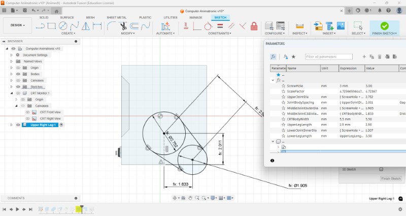
I was able to increase the size of the joints and the foot, with the consequence being I now have to reconfigure the jonts and some other operations.
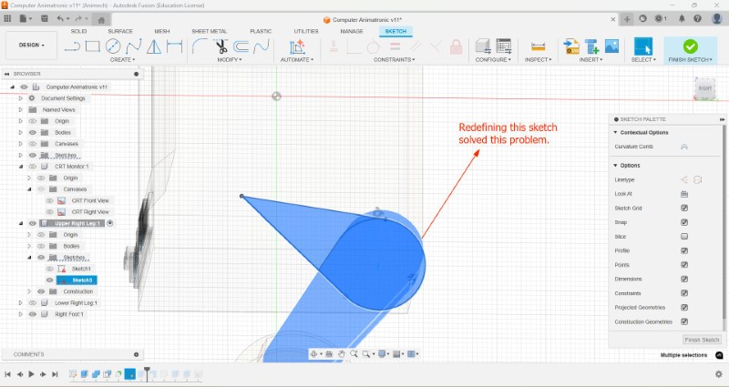
Just like before I tried used the revolve and offset tools to remove more portion of each limb to allow free rotation at the joint, but it didnt work so well, so instead I just drew a sketch and extruded it
But theres this line that I'm unable to remove.
Its very late now. I will go to the lab and get some help from the instructor.
24-02-2025: Next morning on revisiting this problem by hiding the bodies and making only the sketch of the extruded profile visible, I realised the problem was because the sketch was not defined properly because one of the edges was missing, so I redefined it, and the problem was solved.
Now I have to review all the warnings I made because of the changes I had made previously in the timeline. I ended up deletin g them since they what I used previously cutting the cavity, so it was no longer requred
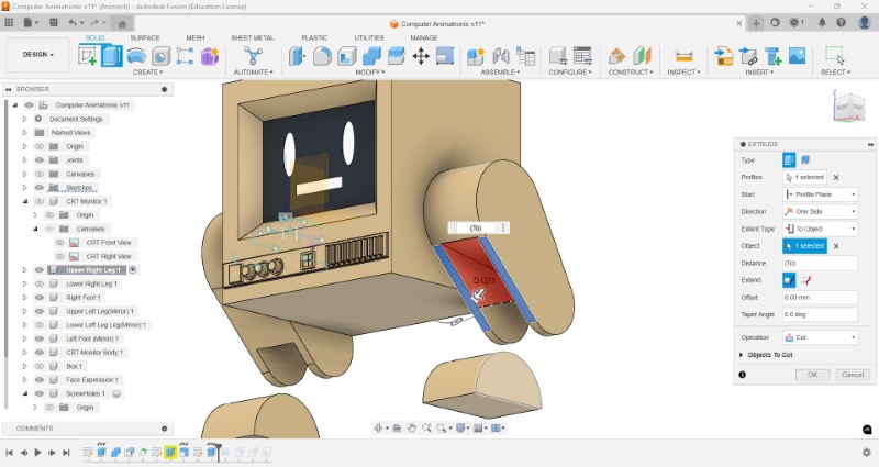
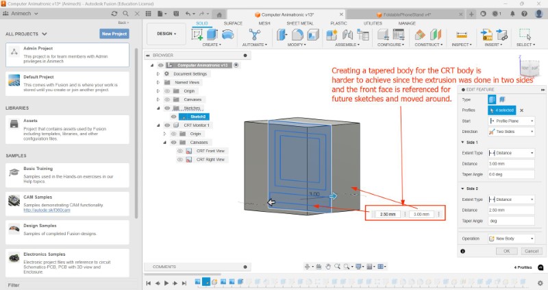
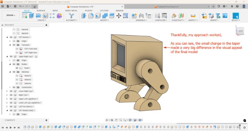
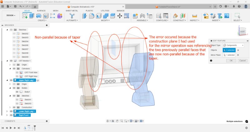
To taper the body, I am planning to modify the extrusion operation to only be extruded from one side from an offset so that any future actions are hopefully not affected. Thankfully it worked out great and I was able to increase the visual appeal of how it looked
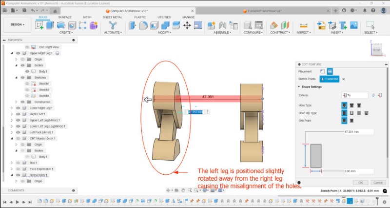
...Or not. The holes are no longer aligned with each other.
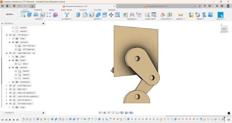
I figured out the error was because somehow the position of one of the legs were not perfectly parallel to each other. this was because the taper caused the previously parallel side faces to converge which led to the mirror operation malfunctioning
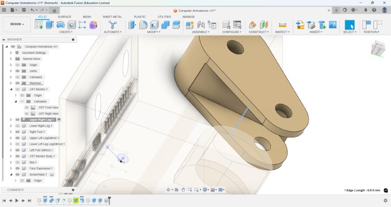
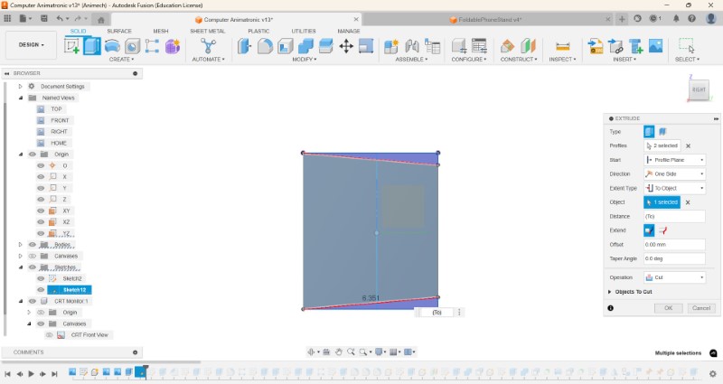
So I removed the taper, instead added a sketch one of the side planes, made a sketch of the section to be cut and extruded using the cut operation. This way it is only tapered on the top and bottom face and not the side faces.
Now the holes are perfectly aligned.
Creating a 3D model using FreeCAD
25-02-2025: I wanted to try making an model of the Main body of my final project from scratch. I was trying to (and failing at) incorporating a print-in-place ball joint acting as the neck to satisfy the requirements for Week 5 and empty space to fit in an OLED screen and some electronics.
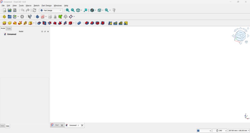
FreeCAD is a free and open-source CAD software that can be used to make 3D designs. To download click click here.
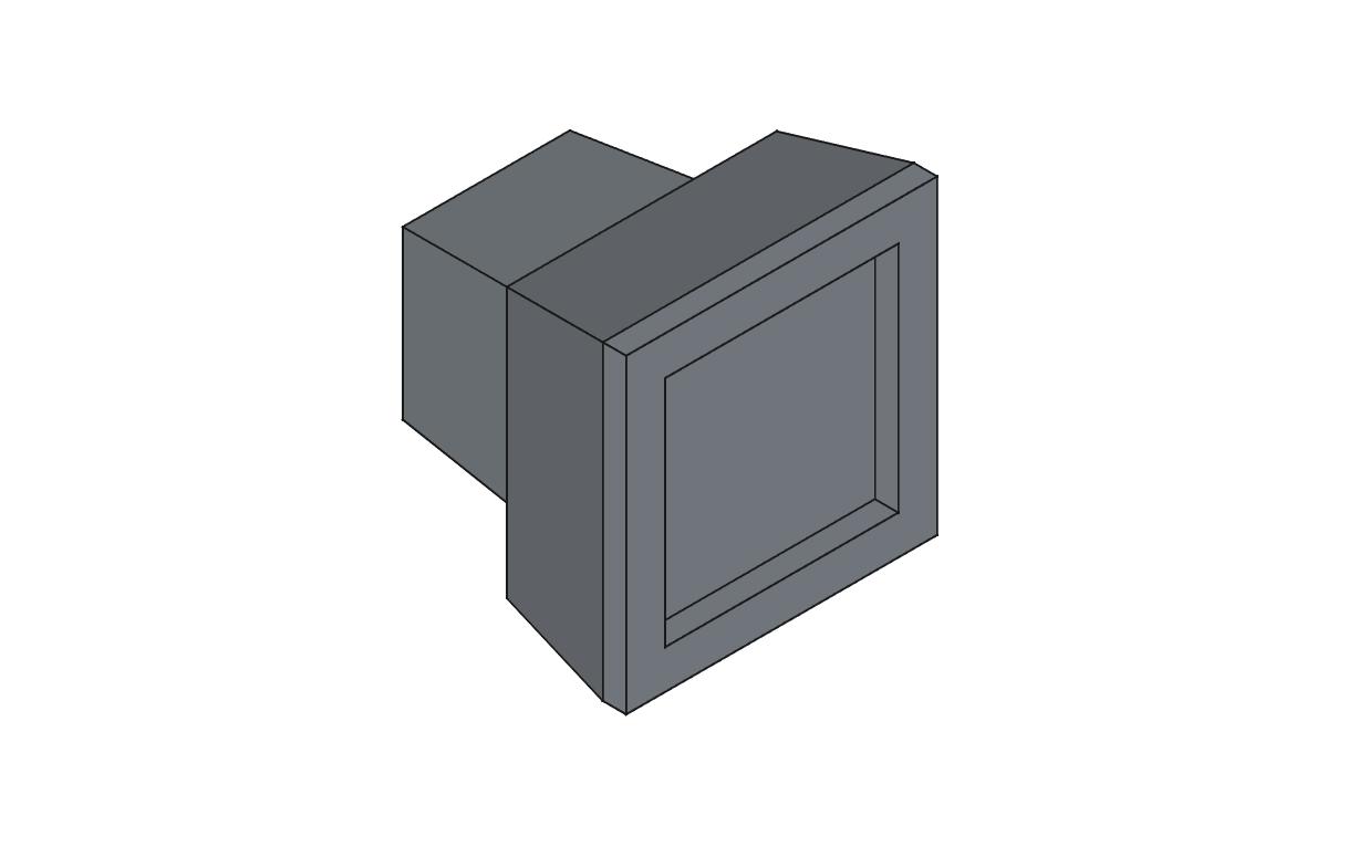
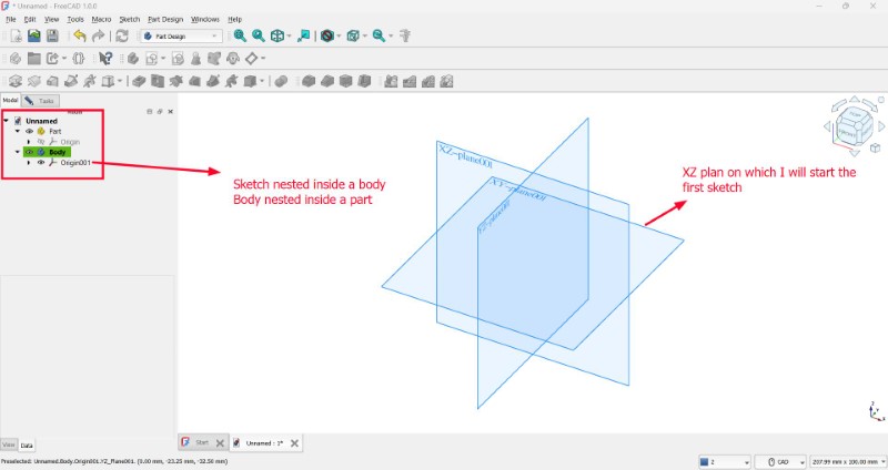
This is what the opening screen looks like. Just like before we first make the box that will form the body.
We will be using this model as reference to make a new design
We make a new sketch nested in a new body which is in turn nested in a new part. I choose the XY plane to start the sketch
First we make a sketch using a rectangle tool and dimension it by clicking on each of the edges.
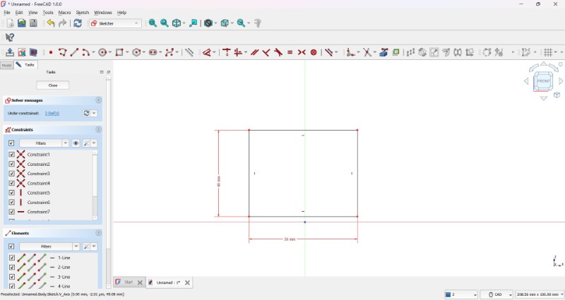
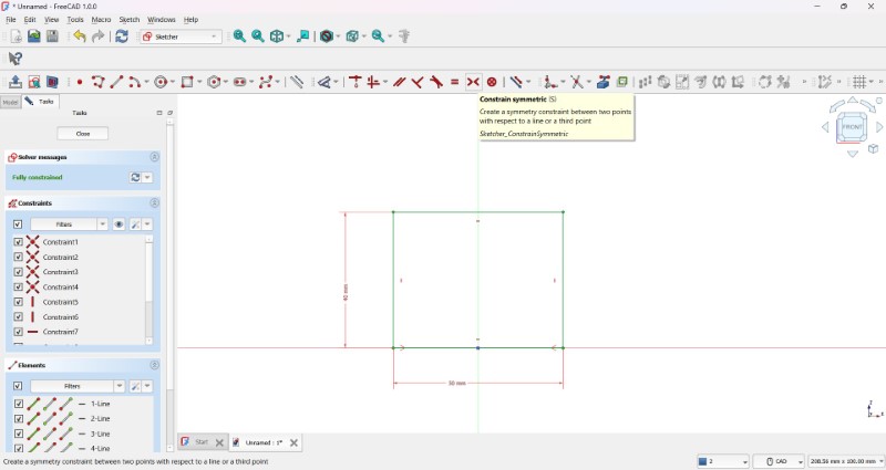
Then I constrain it to the center using Constrain Coincident Tool (letter C on keyboard). To make it symmetric the two edges symmetric to the axis, I used the help of this tutorial. Now the model is fully constrained as shown in the box named 'Solver Messages'.
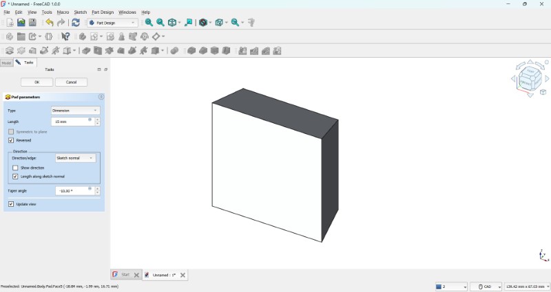
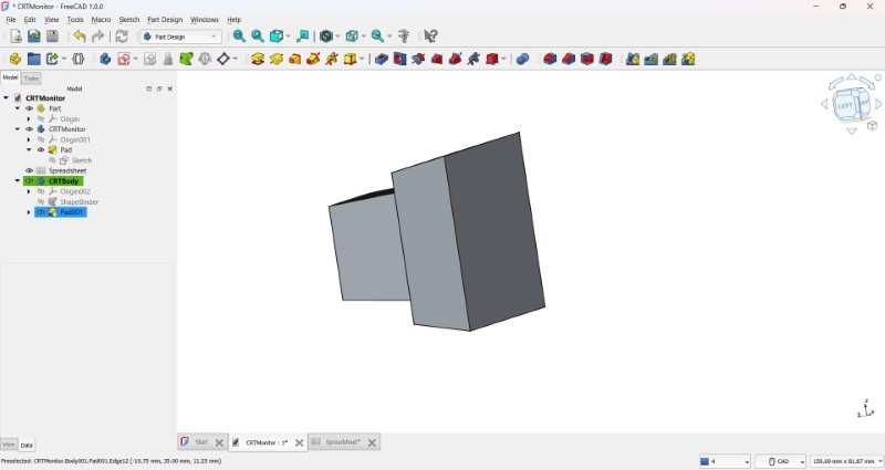
Once the sketch was made, I made used the Pad feature to add volume to turn my previously 2D shape to into 3D. I have used a taper angle to make the box taper towards the back
I used help of this forum post to be able to rotate views
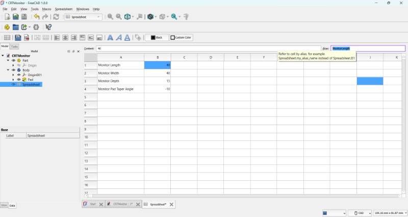
Before we move any further, I wanted to make my part fully parametric. For this I used the help of this tutorial.
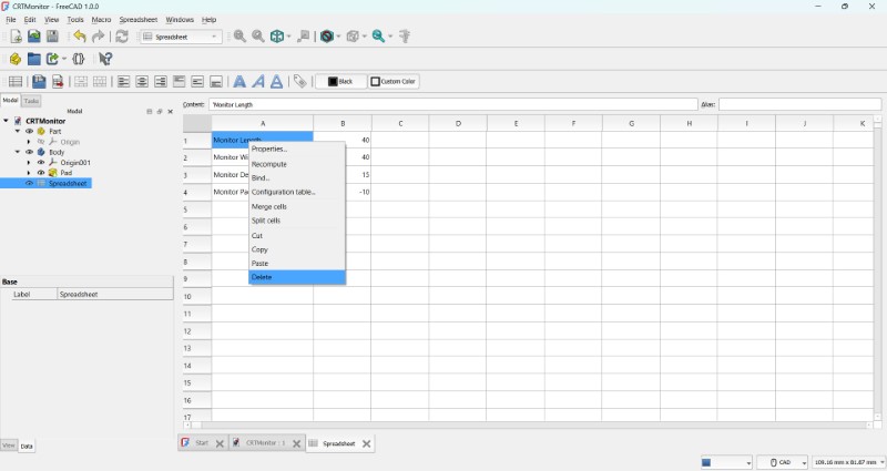
I was running into some error while naming the aliases. What worked was right clicking on the cell, deleting it and relabelling the missing data


Now we add a sketch attached to the back face of the monitor
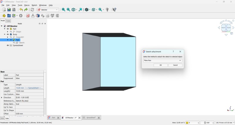
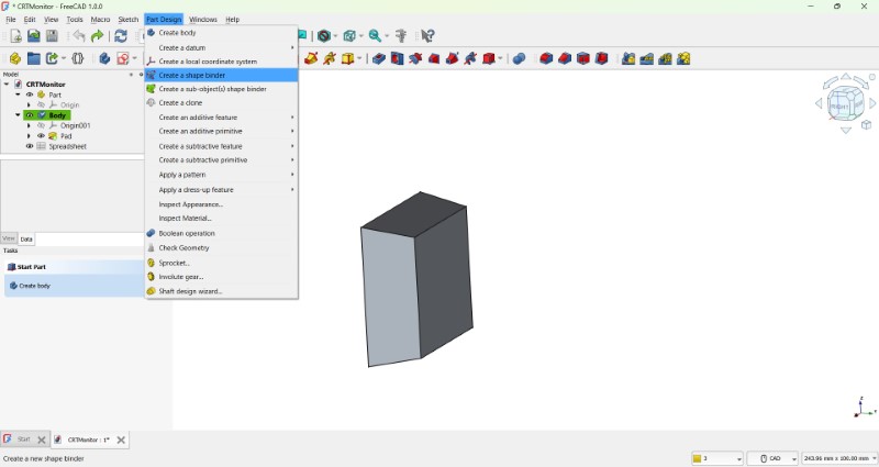
To center the new sketch, I realized we needed 'projections' just like in Fusion. So I went and found this tutorialfor refernce to create external geometry but I was not able to find the Shapebinder tool
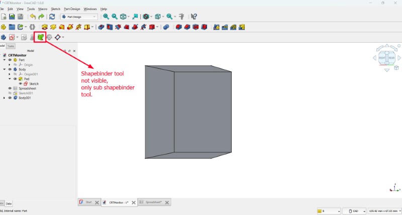
26-02-2025: It is the next day, and I was able to access ShapBinder tool.
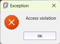
But now I am getting the following Access Violation error while saving, so I closed it and opened and used the recovery option to recover any lost data

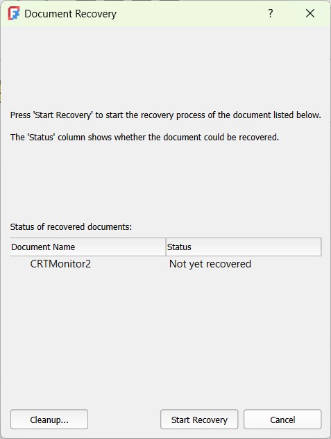
But it did not work. Based on this article, I decided to try restarting my device, which did work successfully.
To make sure this error does not affect my work in the future, I saved the file right away.
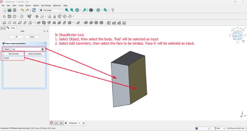
Even though the tutorial did not explain the proper steps to using the ShapeBinder tool, with some tinkering, I was able to use the tool.
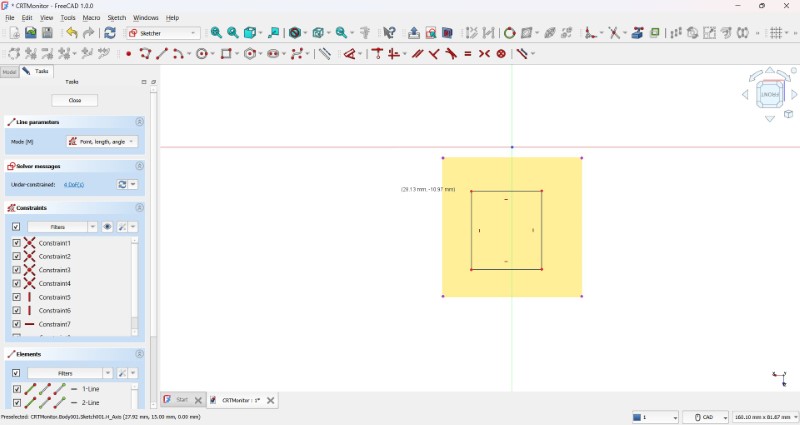
I used the help of this tutorial to center the square inside the outer square. To do so I removed the previous sketch and replaced it with a square I made using the Centered Rectangle tool
After adjusting the parameters, this is what my body looks like.
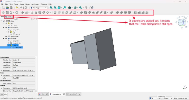
If the options are grayed out, it means the Task dialog box is still not completed.
I repeated the same steps as before to create the rough shape of the body
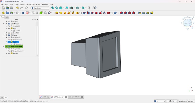
Now to make the inside hollow to house the electronics, I have to first combine the shapes using the Boolean operation and make turn it into a shell
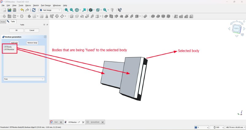
But a problem I ran into is that I can no longer edit individual features using my parameters in the spreadsheet.
So I decided to undo the operation, and see if I can make a shell without combining the bodies. If not I'll try using Part Compound command because it does not merge volumes together.
I wanted to create a ball joint using the help of this tutorial, but I ran out of time, so this will be it for now.
Final thoughts: Compared to Fusion, the workflow in FreeCAD is much more harder to understand. This is partly because I have used Fusion for much longer before I started Fab Academy, but also the interface in Fusion is easier to use. This is my 3rd time using FreeCAD, and only now is the workflow starting to make sense, but I am able to do much more in Fusion. Also since most people around me use Fusion it is easier to ask for help. So I will be using Fusion moving forward.
Creating a 3D render using Blender
Blender is a free opensource 3D animation software that you can use to create beautiful 3D Animations. Recently new features have been added to make it capable of making 2D animation as well.
To download Blender click here.
(Trying) to make an animation of the LCD display in Blender
I was following this tutorial for reference while making this animation. This is how the opening screen looks like in Blender
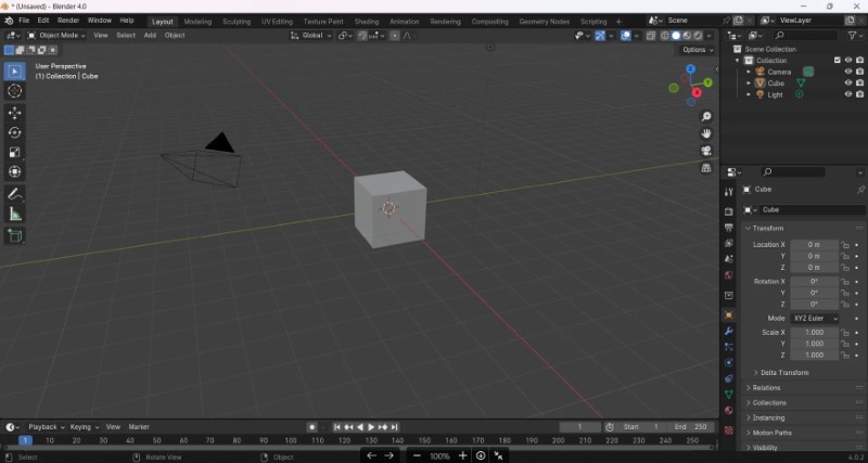
I was not able to directly import STEP files, only individual STL files that have to be assembled together. So first I exported it as a STEP file from Fusion, brought it into FreeCAD, and then exported it as a gITF file, which I then imported into Blender. I later got to know that I can directly import as OBJ files and if I enable a particular option I will be able to import as seperate models that are placed in the same position as the CAD model.
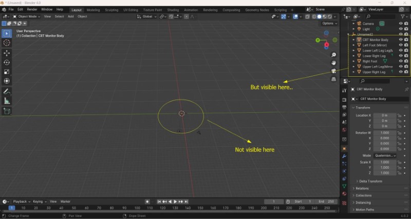
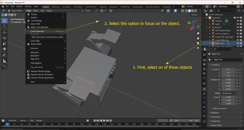
I deleted the cube & imported the gITF file but I could not see it. But in the sidebar you can see the individual files listed, When I went to View>Frame Selected, I was able to bring my objects into focus. After reframing it, you have now sucessfully imported your CAD files as seperate manipulateable objects in Blender.
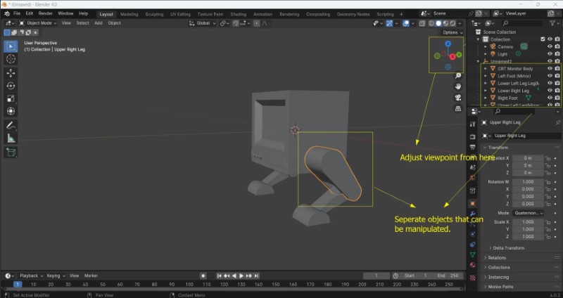
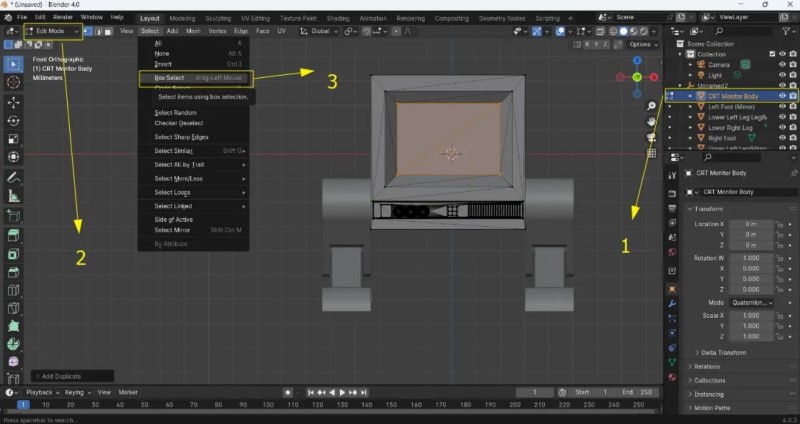
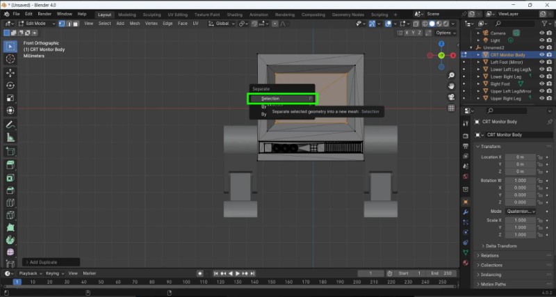
I followed this tutorial to make an animation of an expressive face I then selected the CRT monitor object, changed to edit mode, then used the Box Selection tool to select the face that is supposed to be the glass screen. Selected the rectanglular face, duplicated it to make a new object, renamed it as screen, went to Object Mode and used Grab tool (G) to move it slightly forward the model.
Using forward slash, I can focus on the object. Based on some experimentation, I realized that I had to use Limited Dissolve instead of Dissolve Edges tool to remove the extra edge with destroying the shape. I added a surface subdivision modifier, changed the Viewport number to 2, went back to Edit Mode and used the Extrude (E) command to add some thickness to the model.
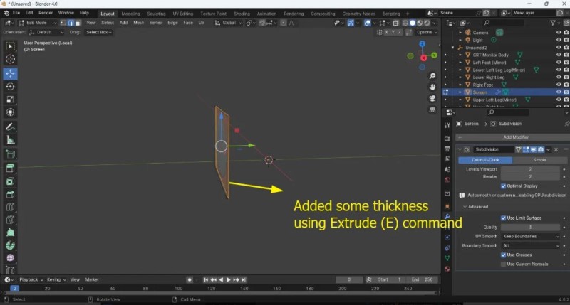
As you can the thickness of my shape is very small, which later became the source of my problems later on.
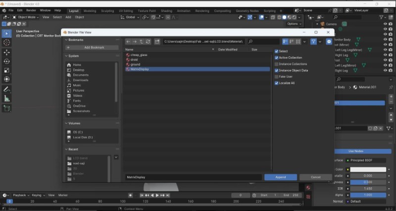
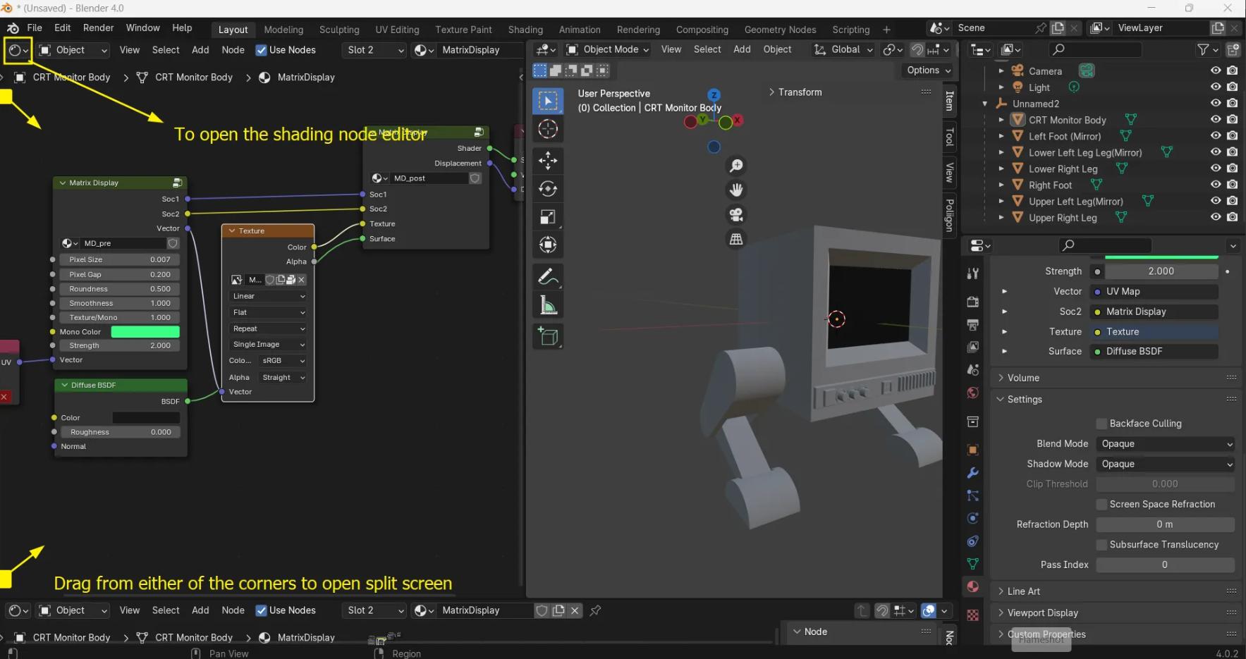
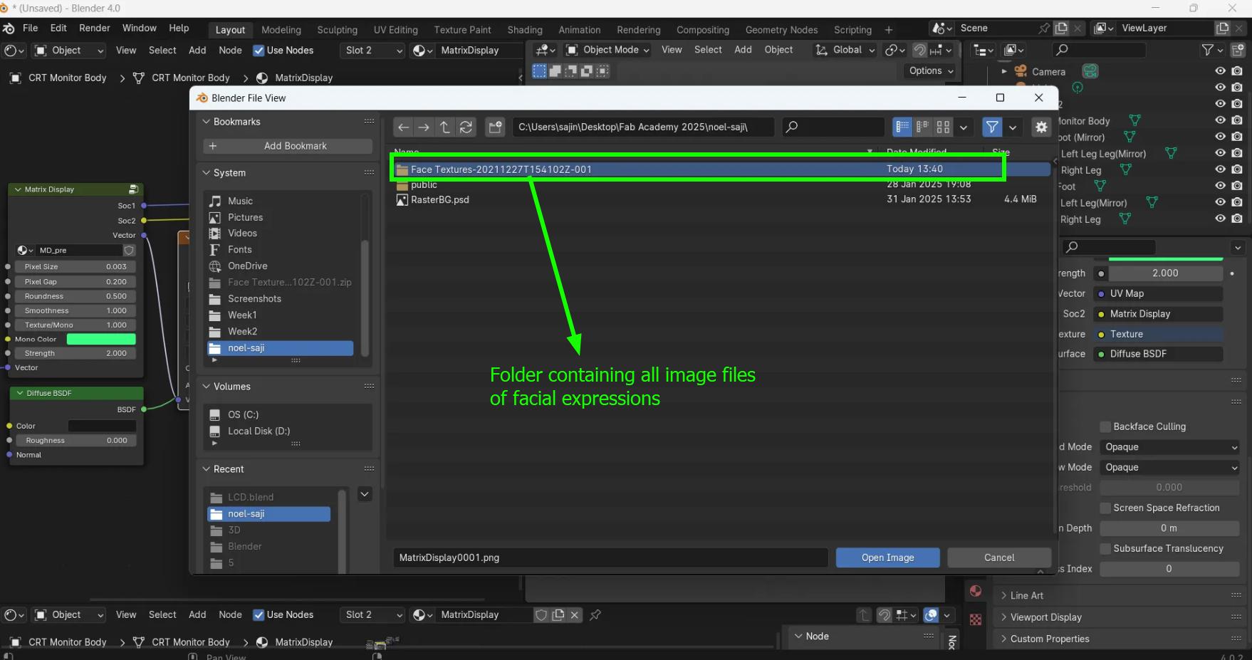
Added both the LCD screen and the CRT monitor to the same mesh (Ctrl+J) and then I appended an Animatable Pixel Matrix Display from BlenderArtists.org. For the faces that will be used here, I followed the tutorial and downloaded some free face files from here
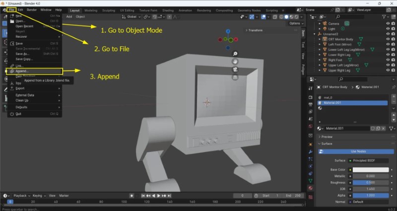
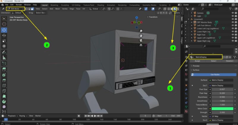
Then go to Material tab and select 'Matrix Display', go to Edit Mode and then View Port shading view to see the material.
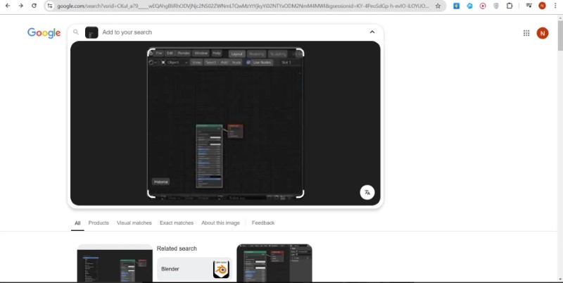
From this tutorial, I found out that I can split screens in Blender by dragging from either of the corners. Because it was not clear from the video tutorial, I ended up doing an image search which led me to this forum post to figure out that the editor being used was the Shading Editor.
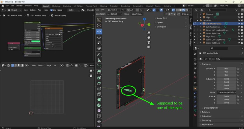
Unfortunately, I was not able to get the UV wrapping to work correctly, and due to time constarints I had to move on to other tasks Since I had not increased the thickness of the screen object by a lot, it was very hard to select all the edges and apply 'Edge Seam' for the UV wrap, and I may have not been able to select the boundary correctly. I will investigate the issue at a later date.
2.2. Compress your images and videos
Resizing/Compressing Images
Previously I had been using an online tool called Image Resizer for my converting and resizing needs. Since I was introduced to some other tools in Neil's class, I tried some of them out.
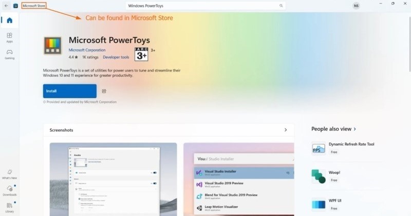
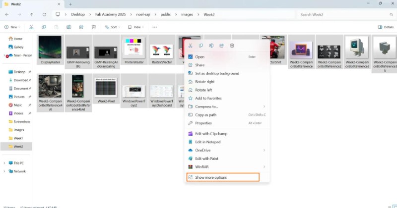
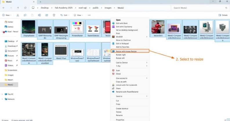
Windows PowerToys
I used Windows PowerToys to manipulate multiple images in batches.
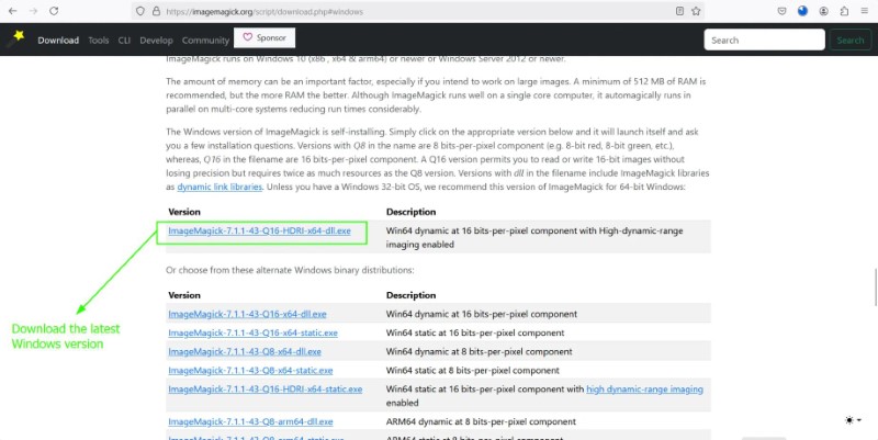
ImageMagick
ImageMagick is an open-source program that lets us resize images from the command line itself.
Click here to download ImageMagick.
Although I understand the potential usefulness of this tool, I was not able to get it to work for my purposes.
I need to be able to:
- Batch convert all files in a folder from other formats into jpg format files.
- Scale all image files to under 100kb.
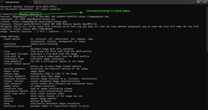
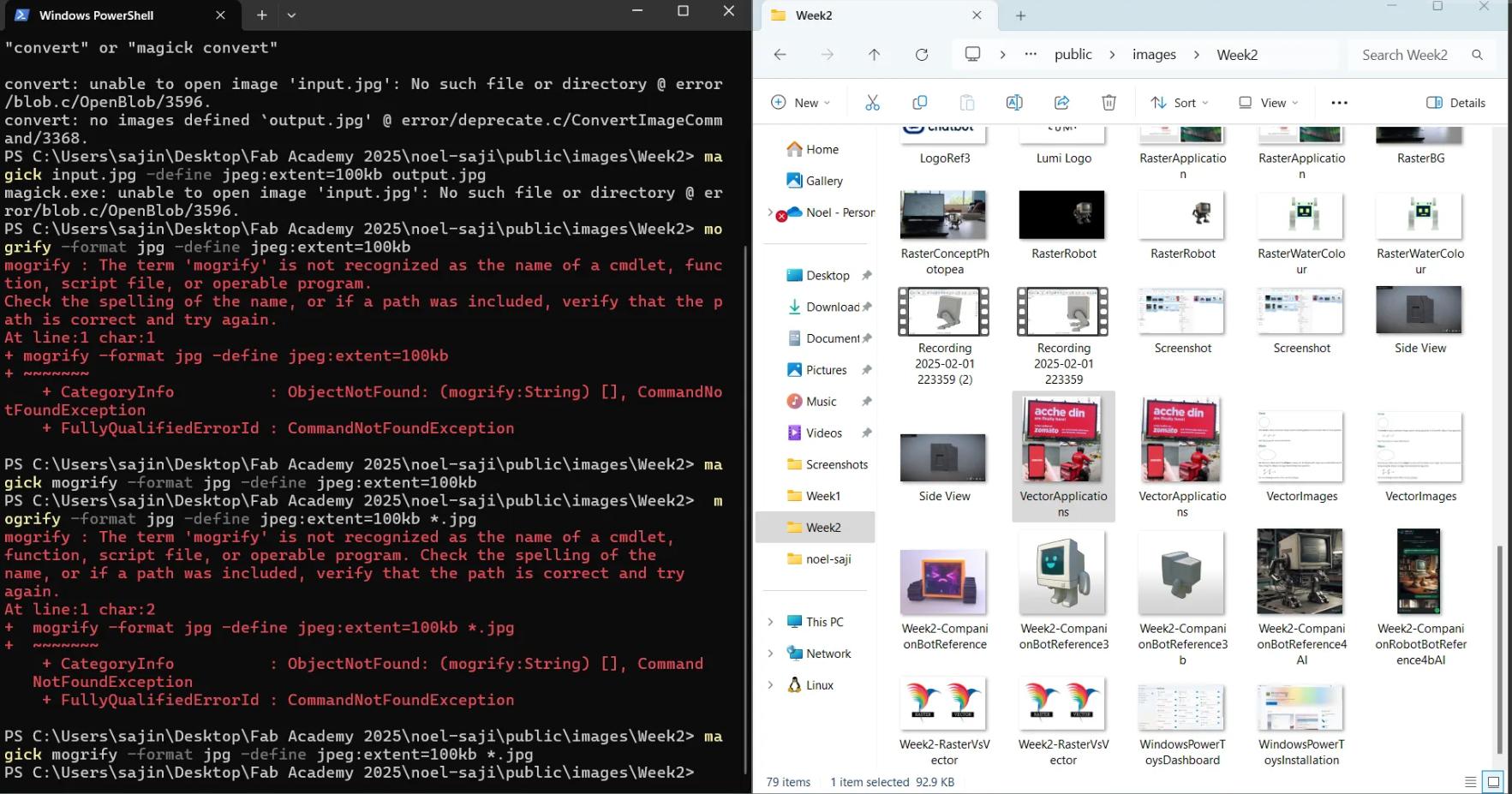
09/02/2025: Thanks to stackoverflow and stack exchange articles these I was able to find the required commands:
                  magick mogrify -format jpg *.png
                  magick mogrify -define jpeg:extent=100kb *jpg
Resizing/Compressing Videos
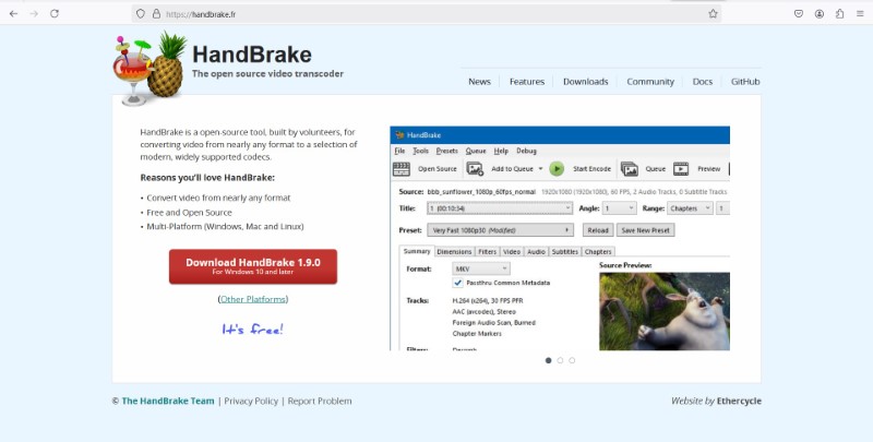
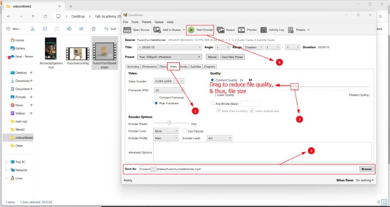
To compress videos I have been using this tool called Handbrake
Handbrake
Handbrake is a free opensource video conversion tool that I use to compress video file sizes. To download Handbrake click here.
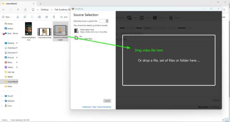
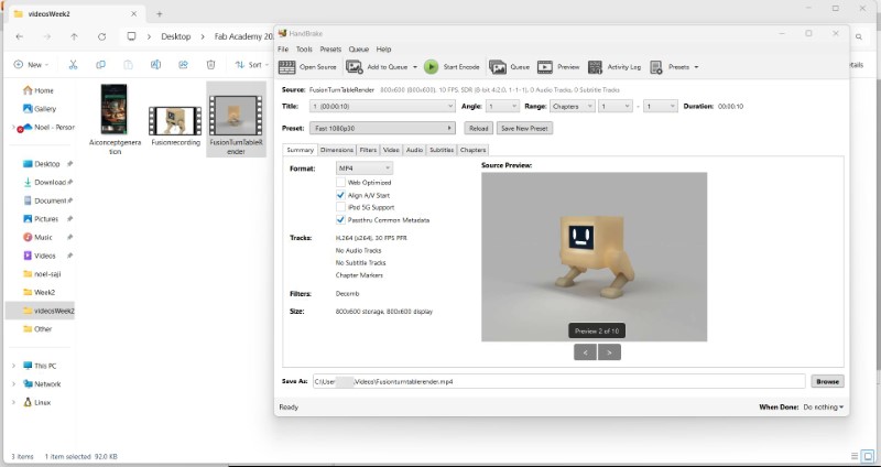
Using the software is simple, drag the file or folder into the software, go to the 'Quality' tab and move the slider to the left, change the directory where you want to save the file and click Start Encode
2.3. Post a description with your design files on your class page.
I have compressed all my design files into a .zip file and linked it to my website.
Conclusion
In this week, I learnt to use multiple 2D and 3D softwares, compress image, video, and other design files and add them to my website.
Mistakes and Possible Solutions for the Future.
- Keep a seperate folder for your assets (including screenshots, videos, and design files) as a back up incase you make unwanted changes while compressing.
- Never overwrite your source files.
- Document immediately after completing a subtask. For example, complete documentation (including git push) of Fusion after using Fusion. This will help you reduce your mental burden especialky during the last few days before your local review.
- Resizing images and videos should be done before writing HTML code or before adding (git) to repository
- 3D; if time allows, learn to make the animation in Blender
- Website updation; if time allows add sidebar with table of contents to aid in navigation
- Check for an add-on that can be used to highlight which section of the HTML code is responsible for which element in VS Code
References
- Additive and Subtractive Colour Theory, Universal Paints
- Mathematics of Vector Art, Interactive Mathematics
- LCD Screen Shader, Blend Swap
- India Today Article
- Fortune India Article
- Tech in Asia Article
- How to Import an Image into Photopea, Tech Deep Dive
- How to Use KRITA - Digital Art Tutorial for Beginners, Winged Canvas
- Blur, Krita Manual
- Meta AI
- Microsoft Designer
- Canva AI Image Generator
- Canva
- 30 Best Robot Logo Design Ideas You Should Check, Kreafolk
- A simple robot logo made by agustriana289
- Andromeda Robotics
- Design.com
- How to change canvas size, LogosByNick "
- Drawing grid in Inkscape in millimeter, Graphic Design Stack Exchange
- Download link for Fusion, Autodesk
- Old CRT television, Sousinho
- Blender
- Blender Character Animation Tutorial: Model and Rig a Cute Robot