5. 3D Scanning & Printing
This week's assignment tasks are listed below:
- group assignment:
- test the design rules for your 3D printer(s)
- individual assignment:
- design and 3D print an object (small, few cm3, limited by printer time) that could not be made subtractively
- 3D scan an object (and optionally print it)
2025/02/20:This week I wanted to change my documentation style to something that was more blog like, I'll be testing if I like it better this week.
The first thing I have to do is look at the evaluation criteria in Nueval Academany
Checklist
- Linked to the group assignment page
- Explained what you learned from testing the 3D printers
- Documented how you designed and 3D printed your object and explained why it could not be easily made subtractively
- Documented how you scanned an object
- Included your original design files for 3D printing
- Included your hero shots
Work Plan
I now spent some time (too much time to be honest) on making a workplan and detailing all the tasks for the week. Also I will be documenting in a rough format like a log as I perform the task instead of leaving it for after I am done with the task. Instead I will use that time only for formating it in a presentable manner.
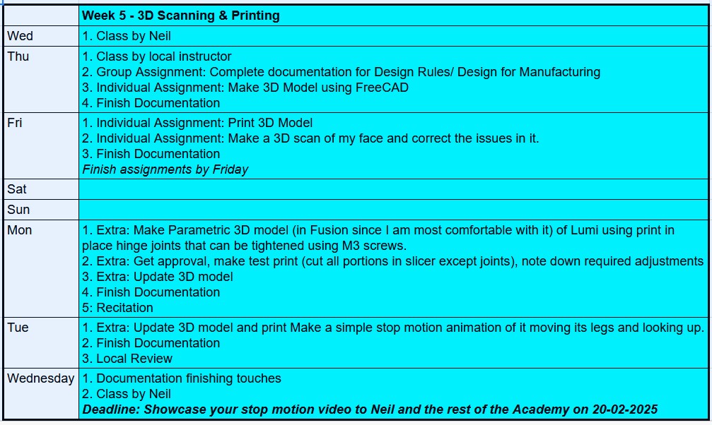
Also, moving forward, I want to treat each week as small mini-project, ie. I have to create a product prototype in each week using the tools I learn in that week. This week I will create a poseable model of my final project that I will use to create a simple stop motion animatin. To make sure I complete the project, I have set a deadline for myself; 20/02/2025.
Group Assignment
21/07/2025: While I originally planned to complete the documentation for our group assignment yesterday, I was not able to complete it on time, so this was the first thing I did when I came to the lab in the morning
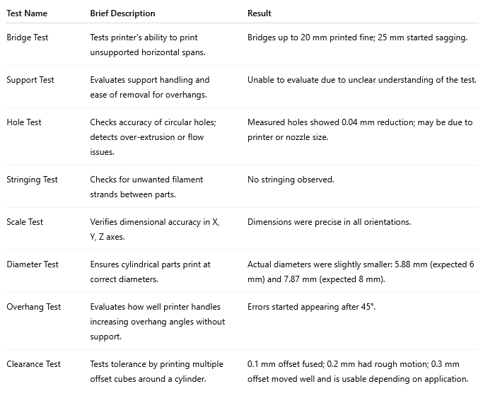
5.1. Test the design rules for your 3D printer(s)
Through this group assignment, we learnt about different types of 3D printing processes, general design rules for 3D printing and specifically for 3D printing in our printer, the Bambu Lab A1
Here is the link to our group assignment.
Individual Assignment
3D Printing
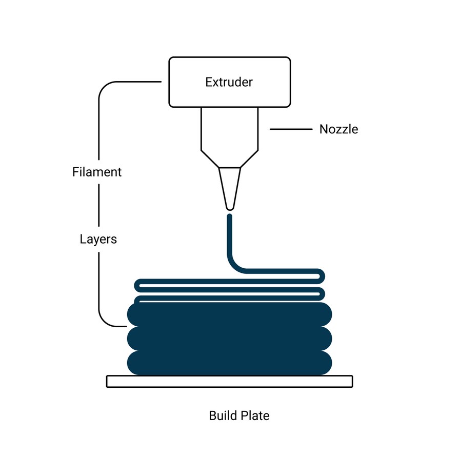
3D printing is an 'additive' manufacturing process where a 3D object is created by adding layers of material on top of each other to create a 3D shape.
3D printing has a number of advantages when compared to 'subtractive' manufacturing techniques like CNC milling
- Less waste produced: Since 3D printing only use the precise amount of material (including material required for supports) required to build the 3D part, it uses much lesser material than subtractive processes that create a lot more waste as a byproduct.
- Better suited for complex parts:Due to the nature of the manufacturing process, 3D printing is better suited for making parts with more complicated geometry
- Better for low-volume productions: When you are making products at small volumes, 3D printers are the better choice.
- Better for personal fabrication:Since the machine is easier to handle than a CNC machine, a non-technical user can use a 3D printer to create custom 3D shapes much more easily
To read more, click here
3D printing has many applications due to the capability to create rapid prototypes of 3D shapes relatively quickly. With each passing year, the types of material that can be used in 3D printing also keeps increasing, which makes the technology more valuable to multiple domains
While there are multiple types of 3D printing, the main types are the following:
- Fused Deposition Modeling (FDM):Also known as fused filament fabrication (FFF); extrudes molten thermoplastic filament (eg:PLA, ABS) that hardens to form the 3D object
- Stereolithography (SLA):Uses resin to cure resin that hardens to form a 3D object through a process called photopolymerisation
- Selective laser sintering (SLS):Uses a laser to fuse small particles of polymer powder (eg:nylon) into a solid srtructure
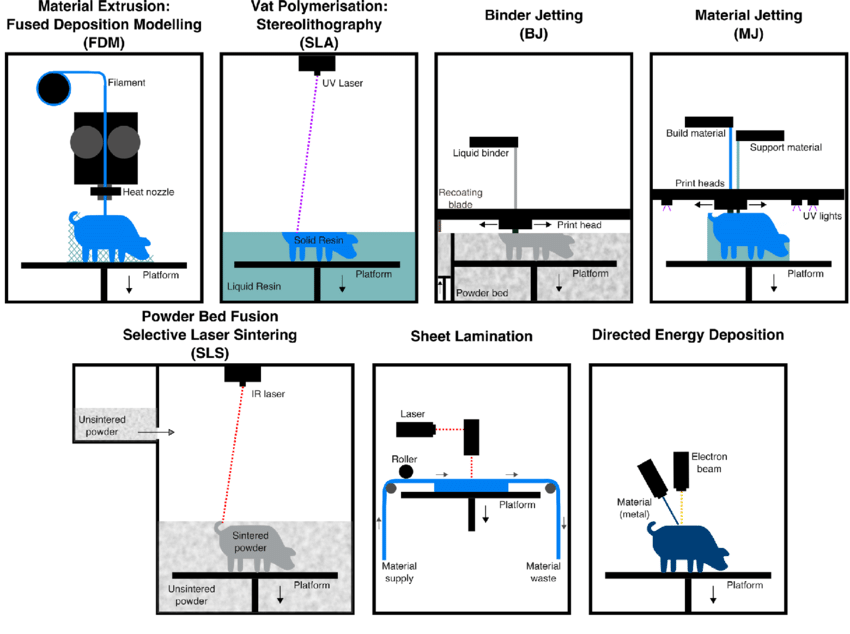
When it comes to motion systems in 3D printing, two popular configurations exist- CoreXY and the Cartesion (also known as Bed Slinger) configurations.
- CoreXY: the belts are crisscrossed in such a way that allows the print head to move independantly of the printing bed, which is stationary
- Cartesian: in this confifuration, the print head moves in the X direction while the print bed moves in the Y direction
To read more, click here.
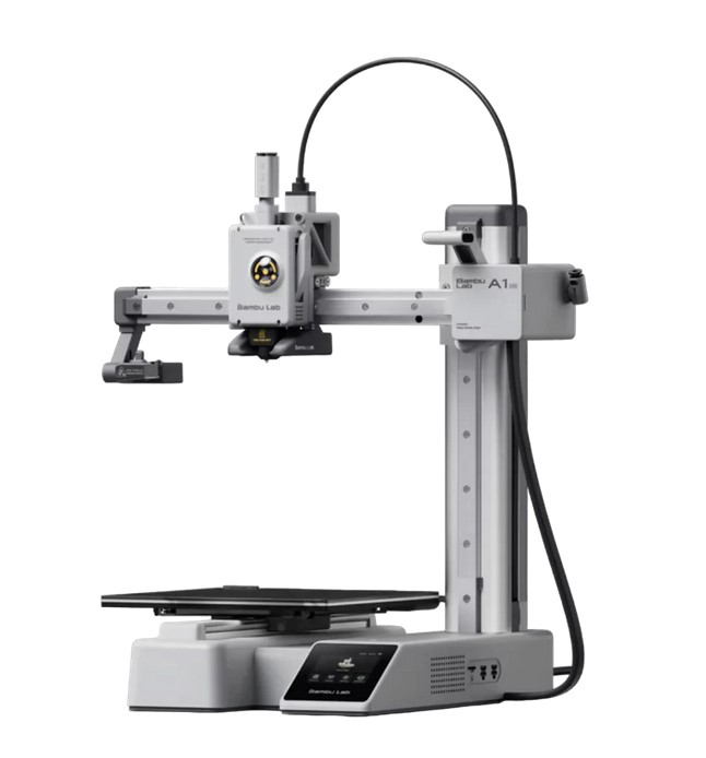
For this week I used the Bambu Lab A1, a compact, FDM cartesian printer from Bambu Lab.
I will be using PLA filament for printing. Polylactic acid (PLA) is a thermoplastic created from renewable, organic sources like sugarcane corn starch or sugarcane. According to this article from Wevolver, PLA is biodegradable if the below listed conditions are met:
- Temperatures above 58°C (136°F)
- Relative humidity above 70%
- Presence of specific microorganisms capable of metabolizing PLA
- pH levels between 5.5 and 8.0
- Adequate oxygen levels for aerobic biodegradation
These conditions are usually met in industrial composting facilities, but are unlikely to be met in home composting environemnts.or in natural environments.
5.2. Design and 3D print an object
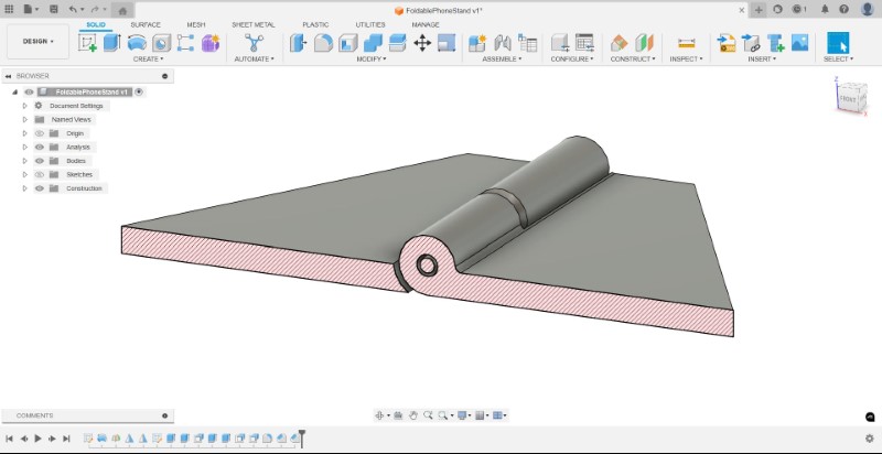
Designing a print-in-place foldable phone stand
Once done with group assignment documentation, I started to look for design inspiration for what I wanted to make. I wanted to make a parametrically designed print-in-place hinge joints because my final project involved two rectangles that had three hinge joints at the foot, knee and body. Additionally, print-in-place joints are hard to make through subtractive manufacturing since you would not be able bend your cutting far enough to be able to cut internal features without first cutting them into two seperate pieces, so it met the assignment requirements. Also, since I wasn't able to properly explore other CAD software in the CAD design week I wanted to give FreeCAD one more try.
I followed this tutorial to make my design. If it works well I might print a foldable phone stand as shown in this tutorial.
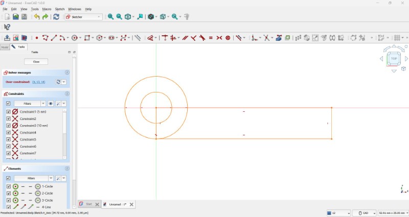
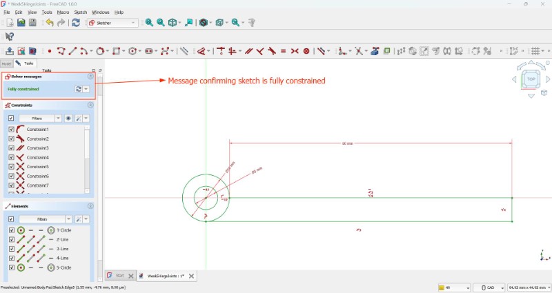
After some tinkering with constraints, I was able to constrain the sketch fully after adding in the dimensions
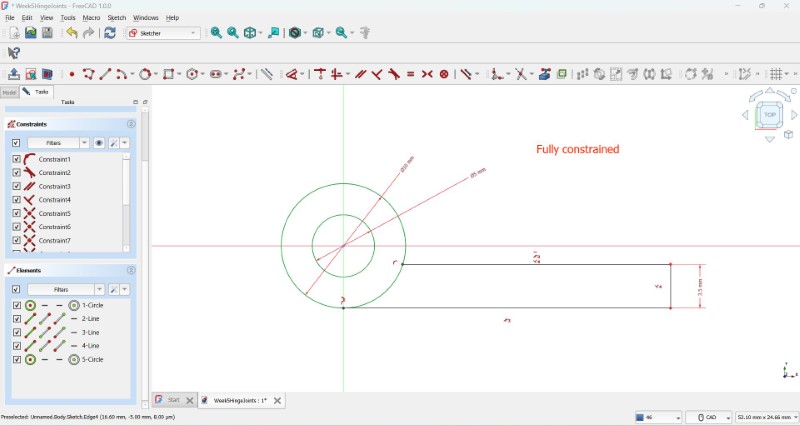
Note: I noticed that it is easier to first select the constraint you want to use before selecting both edges/vertices, which was opposite to the way I operated in Fusion.
I then looked back at the tutorial, realized I had made some unintentional design changes which I then changed.
There was an error in the sketch, wherin the arc passing through the shape cut the shape into two sections that cannot be padded.
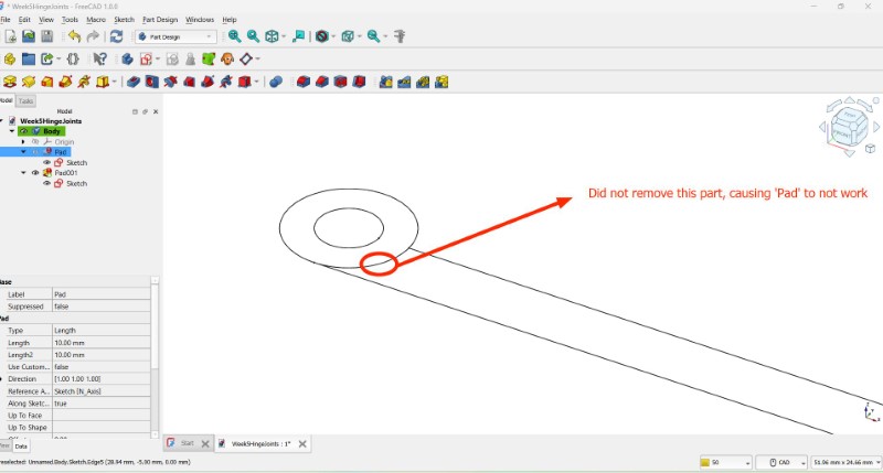
I'm assuming that you cannot select each individual plane and apply the 'Pad' function, similar to how you can do so with 'Extrude' function in Fusion
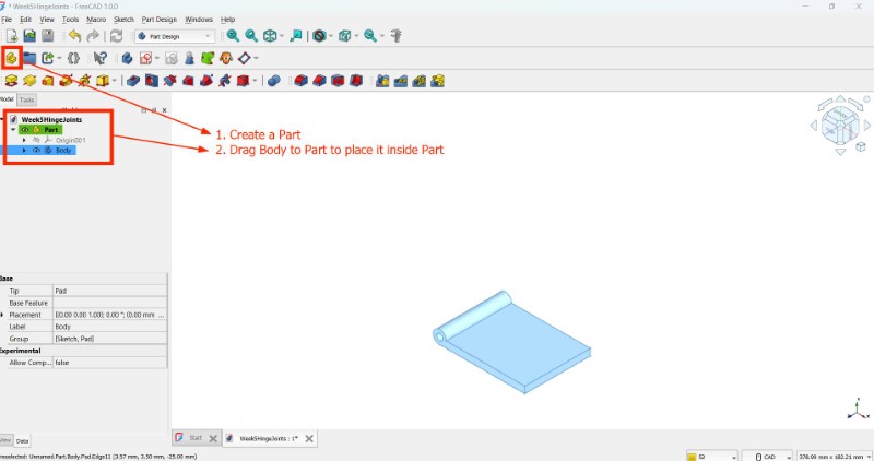
At this point in the tutorial I realised I missed addding a Part and nesting the Body inside it, so I did so now
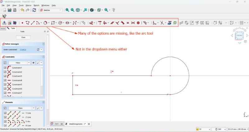
I noticed that many of the tools like the arc tools were missing. I'm sure they are just hidden somwhere
At this point, my instructor saw what I was doing and instead suggested to focus on the aim of this weeek, which was to explore different 3D printing processes and explore FreeCAD only when you have some free time. I found his advice sensible, so I switched approaches and went with Fusion which I am most comfortable with.
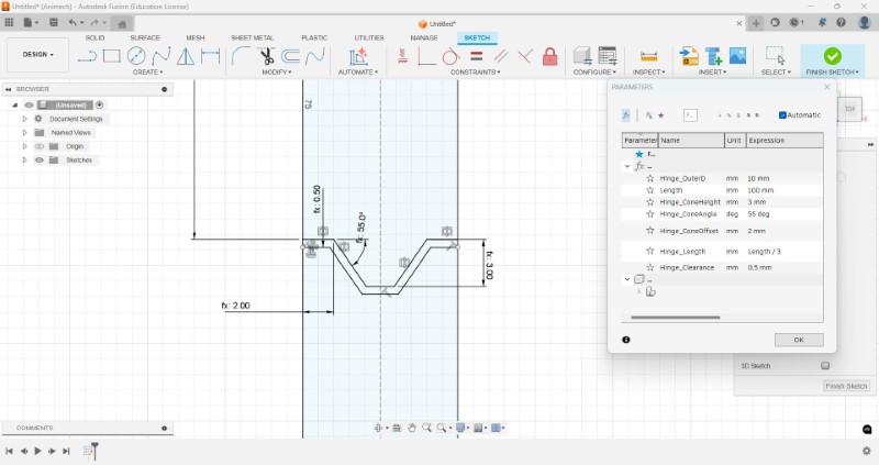
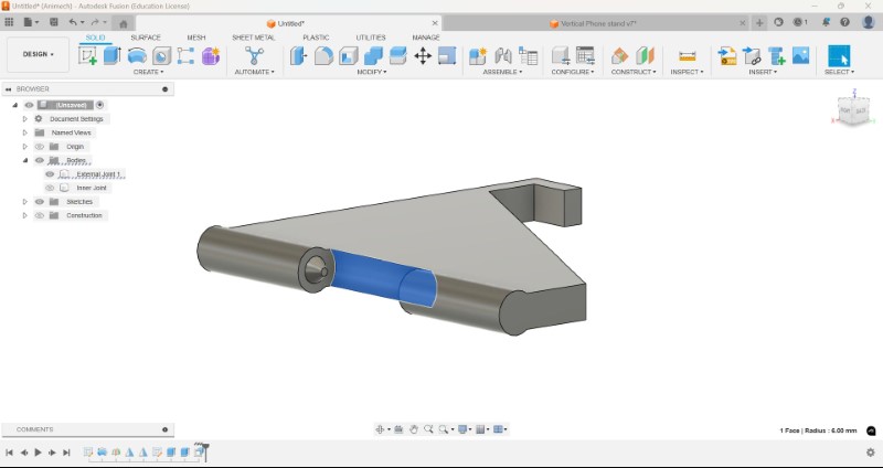
First I started with the sketch for the cylinder that will form the hinge. I will be using parameters here also to make iteration easier.
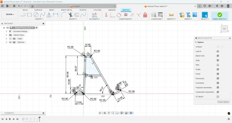
I then created a sketch of the joint, which is fully parameterized
The revolve tool wont work since the projected surfaces would overlap, ie. you only need to make one half of the cross section about the axis of rotation, so I made the necessary changes by removing the mirror half.
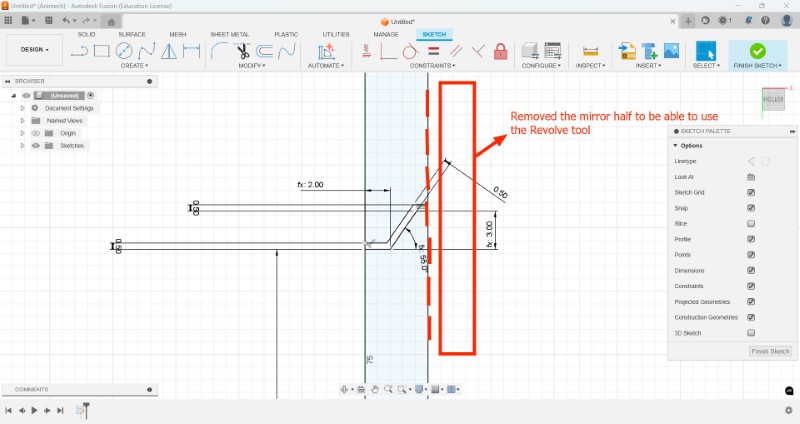
I was then able to remove the Revolve tool
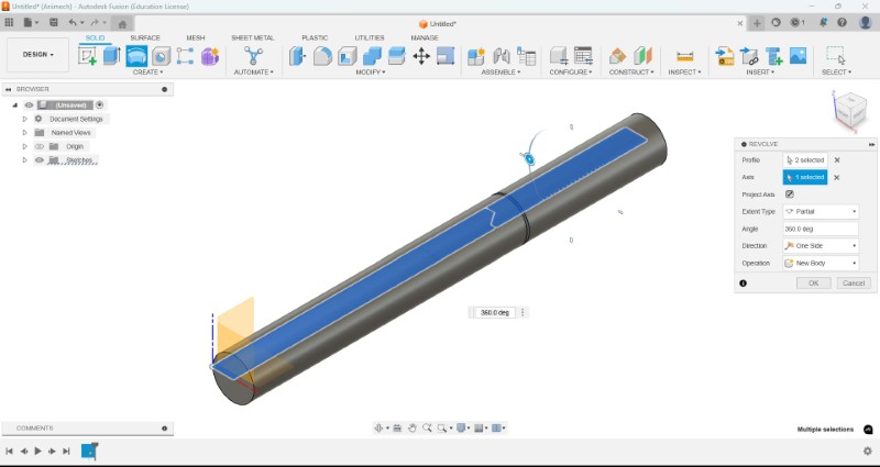
Note: Only sketch one half of the sketch about the axis of rotation to use the Revolve tool
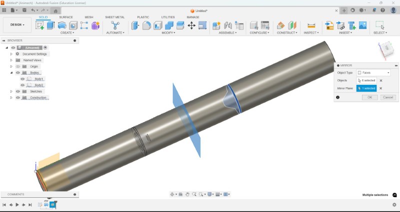
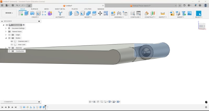
I then constructed a midplane and used the Solid 'Mirror' option to Mirror the faces on the other side.
In hindsight, I shoul have just made the cone that would the hinge joint and mirror opposite to the midplane, and then offset the faces to make the clearance
However, once I apply the operatin, it removes one of the outer cylinders as well
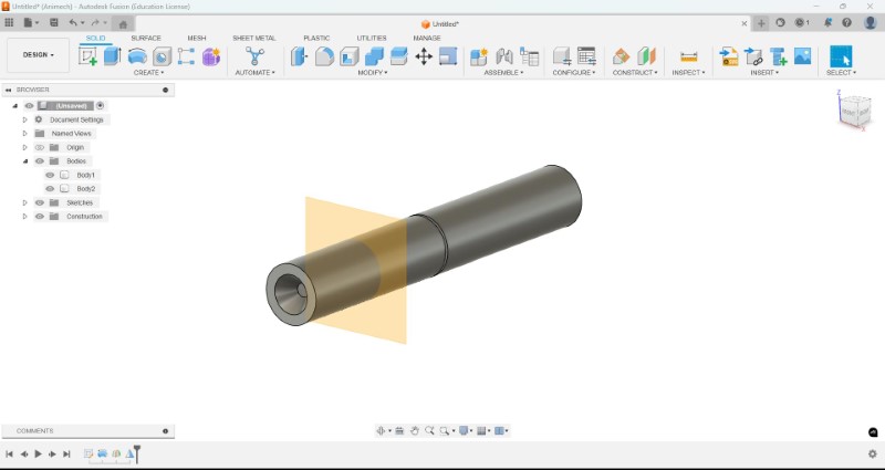
So I used the Mirror tool once more, this time mirroring the body about the same midplane
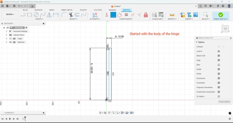
Now I have to make the main frame of my phone stand. To do that I took reference of my previous phone stand design.
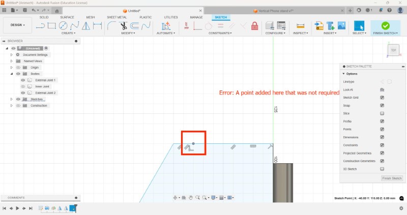
I realized I made an error with my sketch, I had added an extra point, which I then removed and the sketch was readjusted
I then extruded the face connecting the cylinder to the cylinder surface, creating a curved surface
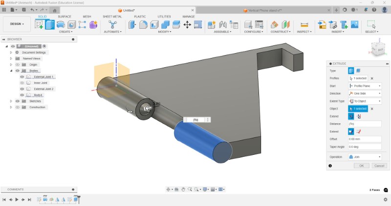
I then offset the of the middle section to give it a 1mm clearance.
I also used the Design History feature to go back and make minot changes in the design so that it would stay completely flat on one surface.
Just like before I created a mirror image of the sketch I made
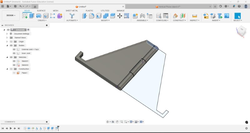
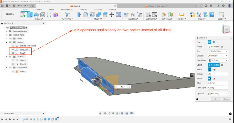
This time I performed the same extrusion as before, but this time, I hid the body so that trhe Join operation would only affect two instead of all three bodies.
Now I have to add fillets so that to add strength to my model once I 3D print it
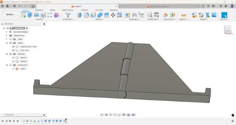
I realized I will not be able to fold the structure, so I have to reduce the extrusion now
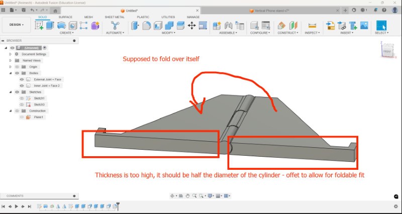
When I presented the model to my instructor, I was told that it was still possible to make subtractively, even though it would be difficult
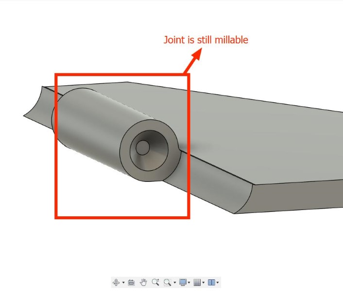
So I wanted to modify my original design to have a cylinder through a hole that is printed in place, making it truly impossible to make subtractively
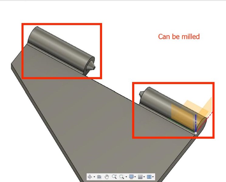
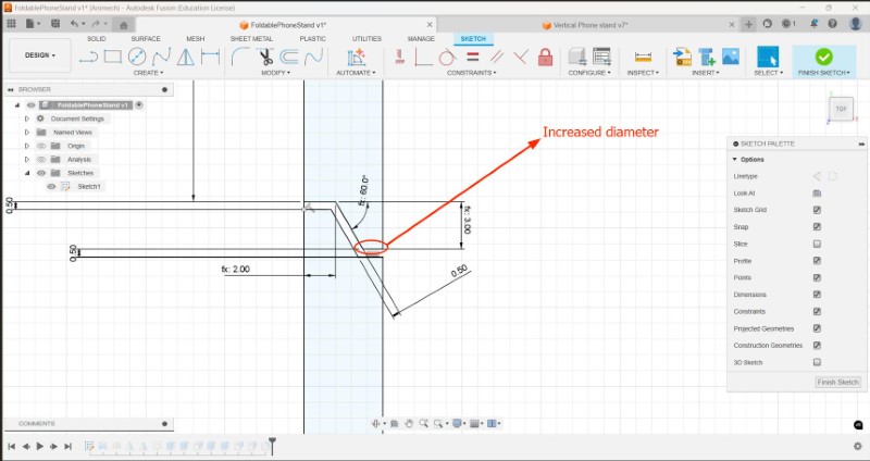
I was also given some advice to increase the diamter of the top of the cone
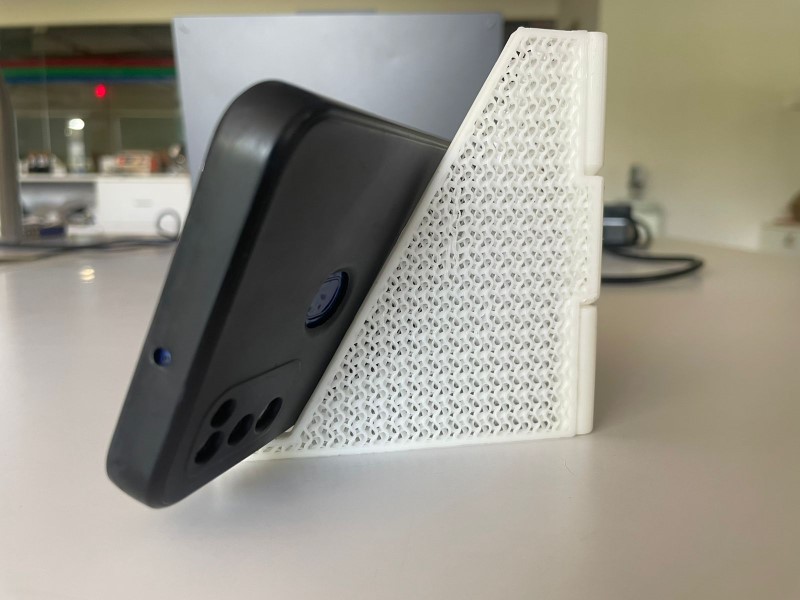
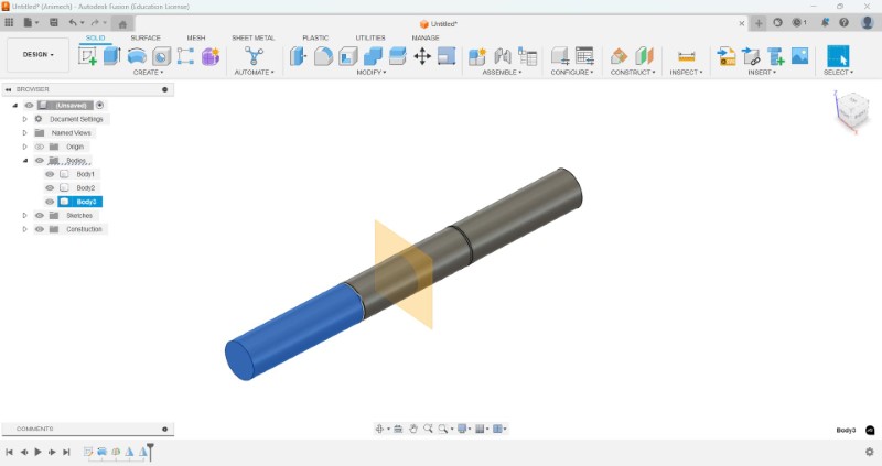
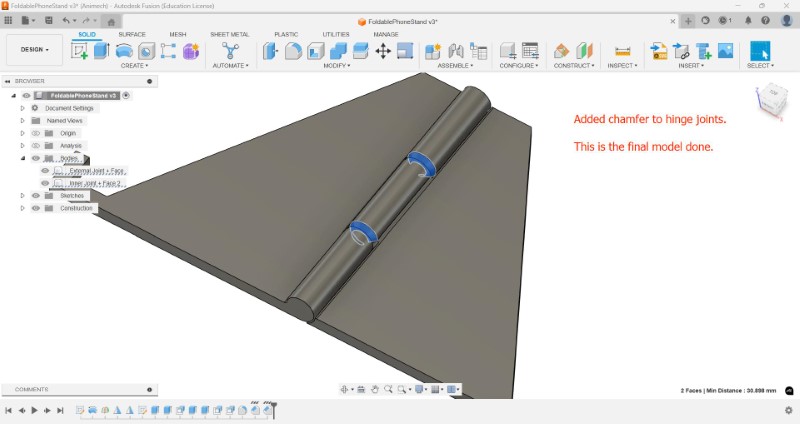
Based on instructer feedback, some chamfer was also added to the cylindrical portion of the hinge joints. The final model looks like this.
3D printing my model of a foldable phone stand
Since we are using a Bambu Lab printer we are going to be using Bambu Studio as our slicer software.
To download Bambu Studio click here.
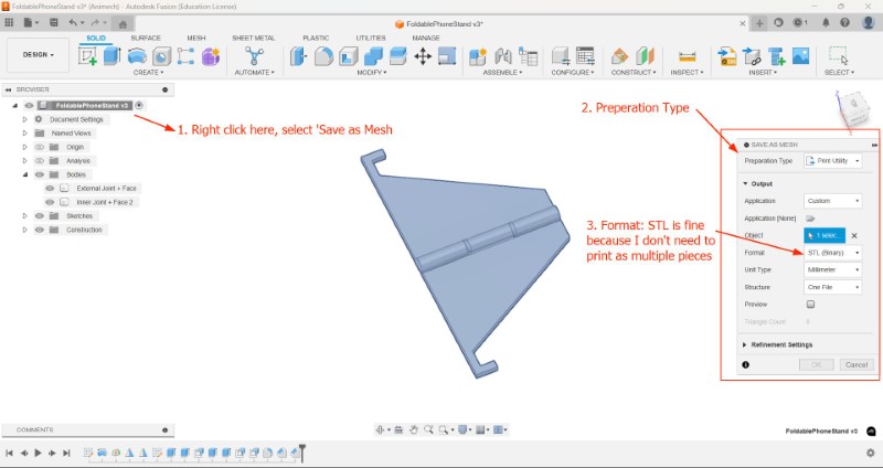
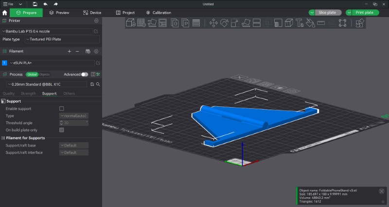
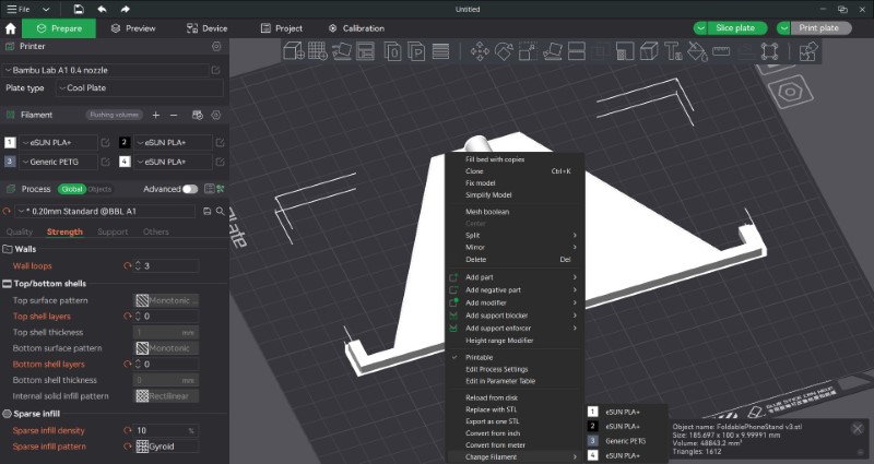
To export our model, I go back to Fusion and export using the 'Print Utility' option, which opens the model directly in Bambu Studio. I am exporting the model as an STL file since I dont have multiple parts that need to be manipulated
Once we click 'OK' Bambu Studio should automatically open like the image shown below.
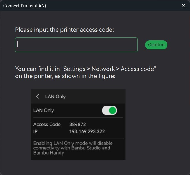
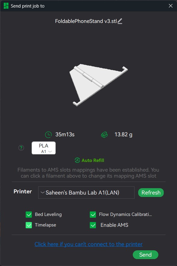
Fist, I connected the printer with our computer over LAN using the a passkey that can be accessed from the printer itself connect wth the printer by LAN
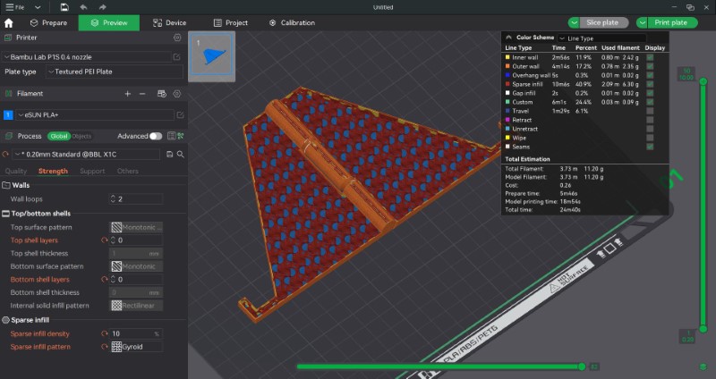
To remove the top and bottom outer shells and expose the internal fill pattern, I used this tutorial. I then sliced the model using the 'Slice' option at the top right of the screen to reveal how it would look
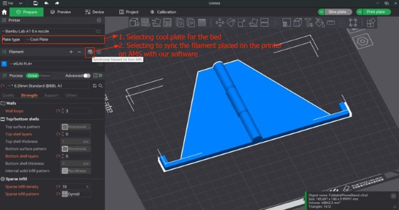
Since we are using a Bambu Lab Cool Plate which is a replaceable print surface sticker that is applied on the printing side of the plate to improve adhesion with PLA filament be Then I selected the 'Cool Plate' option and syncronised with filaments in the Automatic Material System (AMS), which is a system that can store and monitor multiple filaments and send the required data to the slicer software.
Problem with wall loops: I wanted to keep the hinge as strong as possible so when I saw that there were gaps in the outer perimeter walls I tried increasing the number of walls but it did not work. I eventually just went forward with the print and testing the effect of lack of perimeter walls on the hinge.
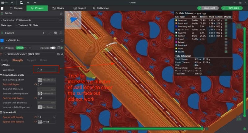
Since I was pushing far more than the limit of overhang lengths that we tested for before in the designing of the hinge, I was worried that supports would be required which would add unnecessary friction to the hinge. If supports are required, a message should pop up saying that there are some 'floating' structures that require supports to print properly. Since the message did not come up, I assumed that they were not required.
We then selected the filament we wanted to use and sent the model to be printed.
I tried enabling the timelapse feature but did not use the recording in the end.
Attempt 1: Failure
My print failed because the the print head pulled out the edge of the print from the print bed, which meant that any new filament would not properly adhere to the layer below it, causing 'spaghetti'
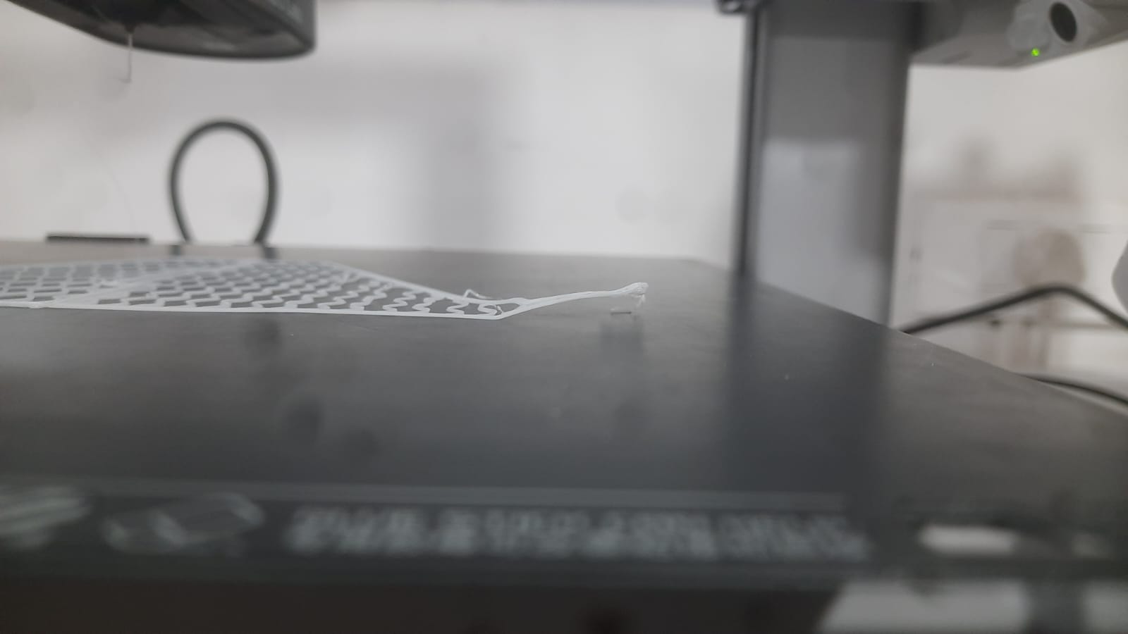
I think this was because of the lack of adhesion due to the lack of the outer shell
I decided to add an outer brim of 5 mm to the outer edge of the print
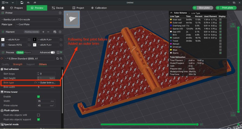
Attempt 2: Failure
My print failed, this time, the entire layer was pulled off the bed.
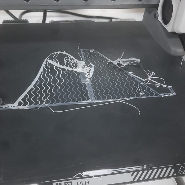
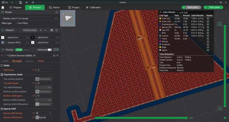
The brim did not offer enough adhesion to the print, especially while printing the first few layers. After talking with the instructor, I decided to increase the solid infill density from 10% to 20% to increase the amount of surface area for adhesion with the printing plate, even though it would decrease the visual appeal of the stand.
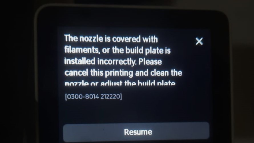
Attempt 3: Failure
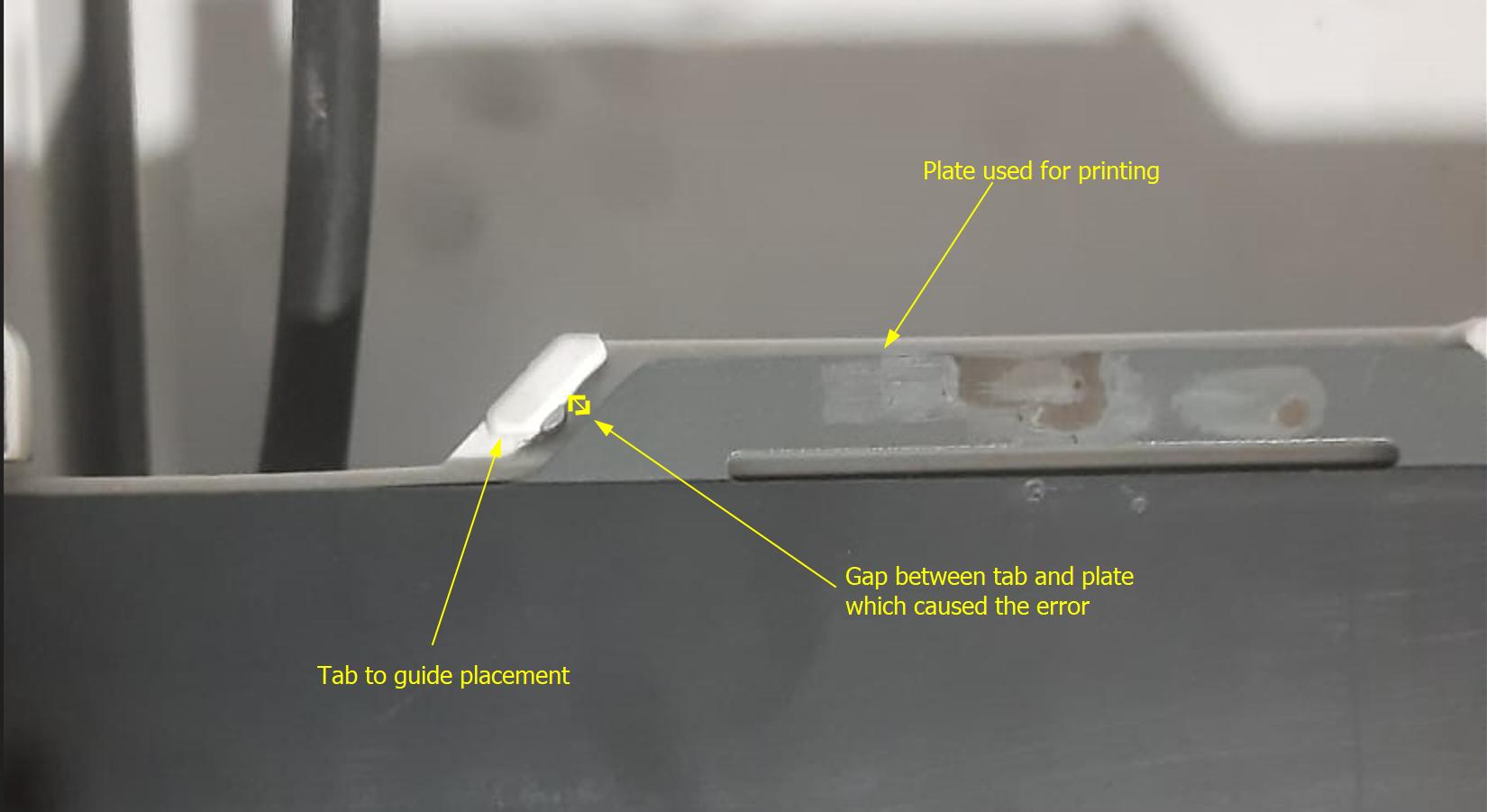
This time, even though the layers seemed to be printing fine until it suddenly stopped. The printer display showed the below shown error.When we checked, neither the nozzle, nor any of the internal components of the head (viewed by removing a magnetic cover) showed any signs of clogging due to hardened filament, so that cause was ruled out. But when we checked the alignment of the build plate, I realized that the bed was not in perfectly aligned.
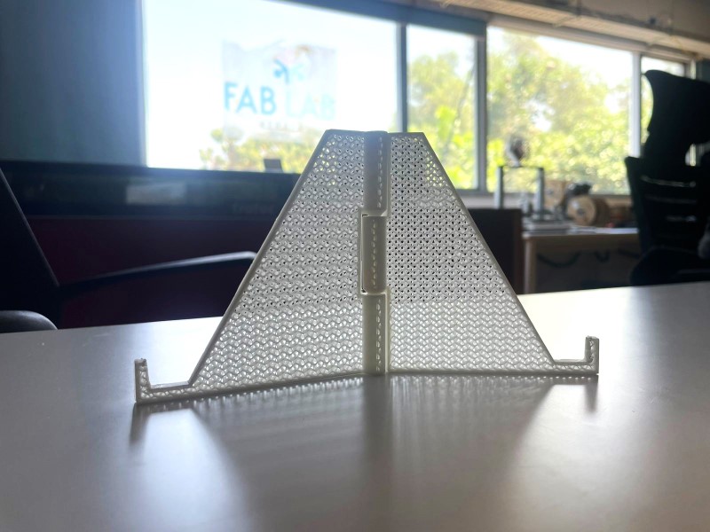
Attempt 4: Success!
This time the print worked as expected.
Post processing
Now that the print has been sucessfully completed its now time time for some post processing. Here we remove the supports, clean up the edges, removing any excess filament and sanding it for a clean finish if required.
This is what the final product looks like
5.3. 3D scan an object (and optionally print it)
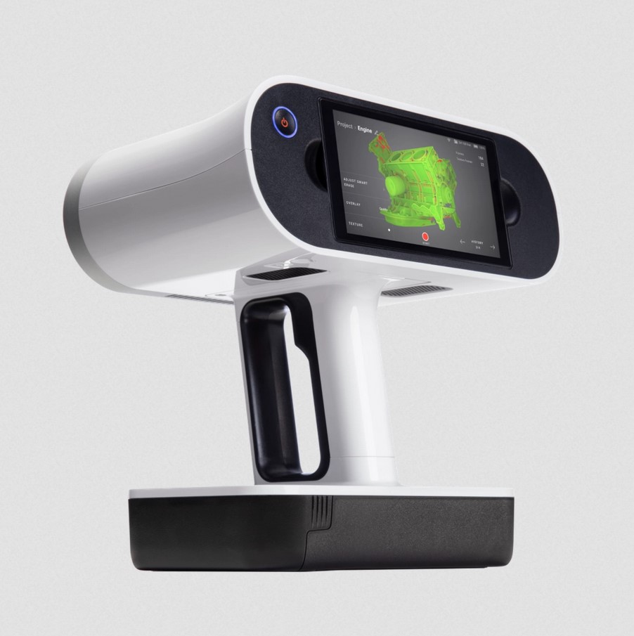
About 3D scanning
3D scanning was done using the Artec Leo scanner which is wireless and AI. The way it works is by sending out laser light rays from laser-emitting diode which is sen which hits the object and is scattered at different angles. Some of these rays get reflected back and is captured at another camera on the machine which records the time it took for the ray to be captured and the angle of the incident ray.
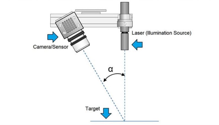
The angle of the incident ray can be measured by the camera sensor and since the distance between the camera sensor and projector is known, the distance to the point of reflection can be calculated in 3D space using trignometry . Once you collect millions of these points, you can connect them together to create a 3D model in space.
The main advantages of the Artec Leo is as follows:
- A ring of LED lights light up the model at the same intensity each time, reducing errors due to varying lighting conditions.
- In case a portion of the scanned image was not scanned properly, we can go back to that point and start scanning. The data is integrated back into the existing model without any issues. This feature is not possible wih most other 3D scanners.
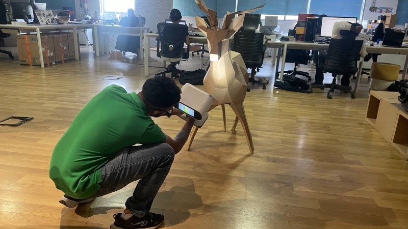
Using the scanner
To practice scanning, I used a cardboard model of a deer that was previously made at our lab by Ashish Joy who is a fellow Fab Academy student at our lab. Click here to read more on the making of this cardboard model. While the process was greatly simplified because of the printer, it was not without issues
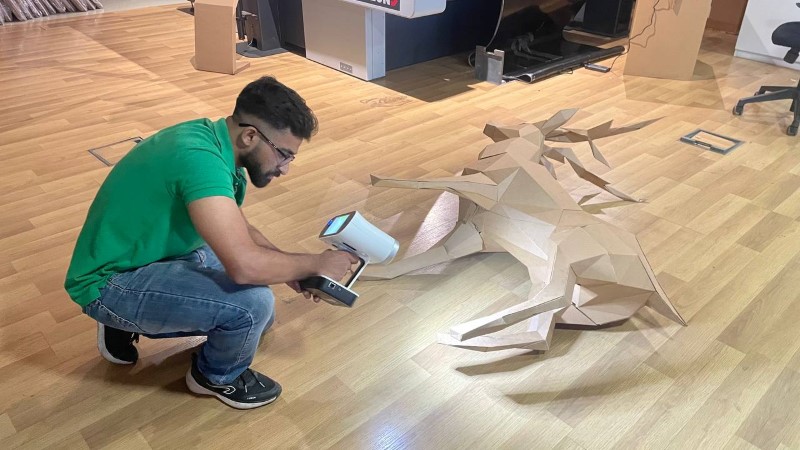
- Edges of the cardboard model where multiple cardboard layer are joined together are very hard to scan, even when I tried to scan from multiple angles and reduce the distance from the model
- Scanning the underbelly was a struggle so I had to change the orientation to be able to scan the model properly.
- Scanning thin features like the legs were problematic, probably due to the lesser number of light rays that get reflected back to the camera. I do not know if the fact that the legs lie very close to the ground had an added effect in my struggle
Processing the scanned model
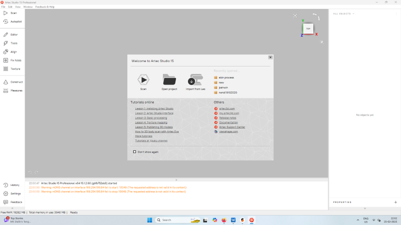
First we download Artec Studio to manipulate the data from the scanner and export as a STL file. To download click here.
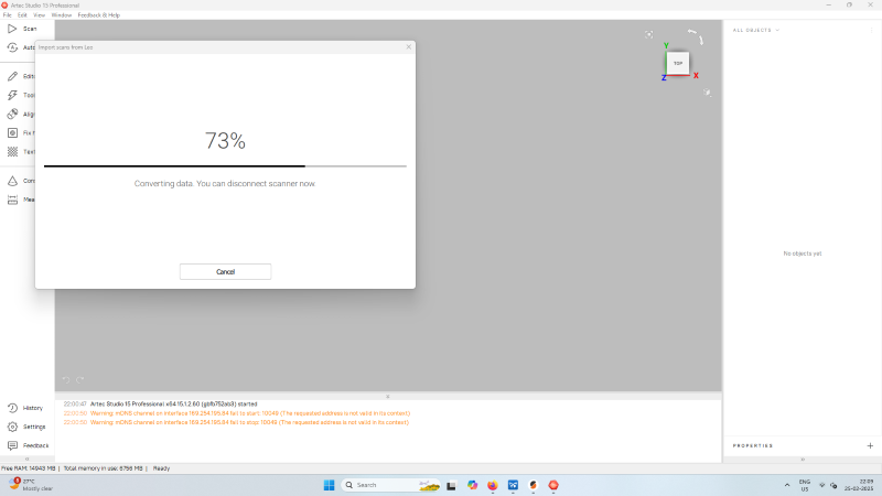
I connected the scanner via LAN cable, and import the data. While connecting, ensure that you are in the main project page in the scanner.
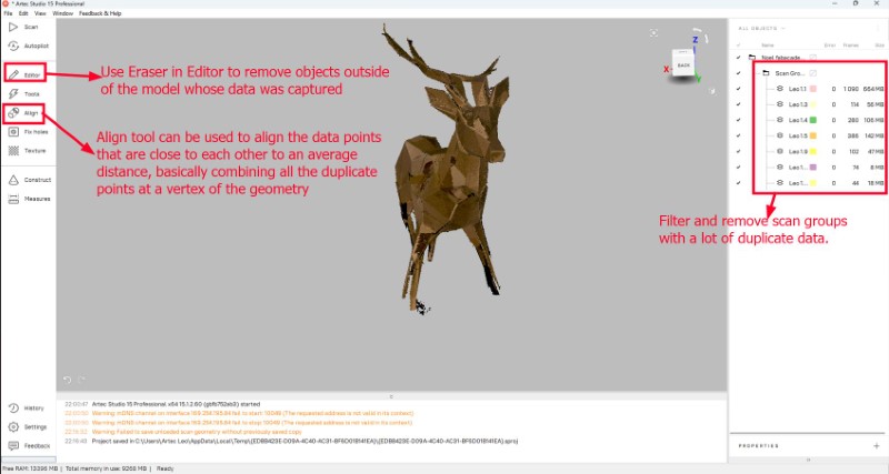
Once the data has been imported, the first step is to analyze each scan group and reduce the amount of duplicate data by as much as possible. We do this by right clicking each group, and showing or hiding each group and comparing the difference visually. The groups that are not required to be computed can be unloaded by righclicking the scan group and selecting 'Unload'
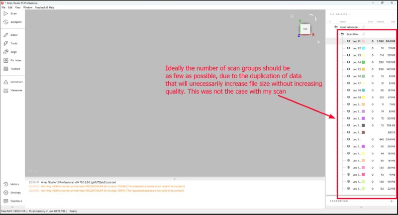
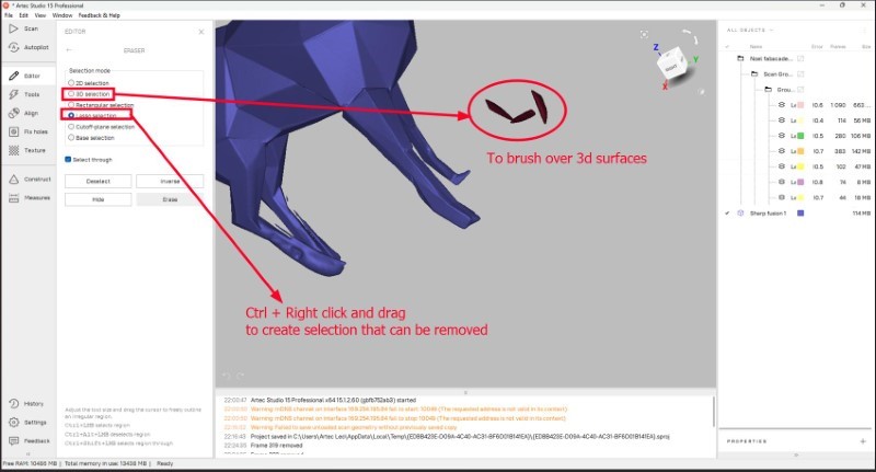
This is how my model looks after removing all the scan groups that were not required and using the Eraser Lasso tool in Editor. To use the tool, I press CTrl + Drag the cursor to select the area to be removed, then I press Delete on my keyboard. Then we use the align tool to combine all the points close to each other to a single point, effectively reducing the complexity of post processing process.
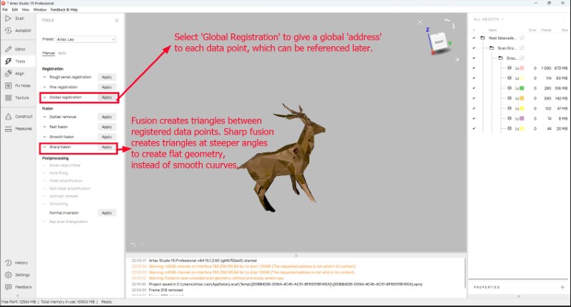
Next we go to 'Tools' workspace, where we use the 'Registration' and 'Fusion' commands to create the triangles and convert the data into a 3D shape.
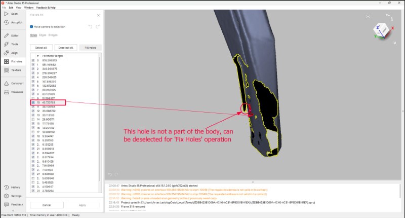
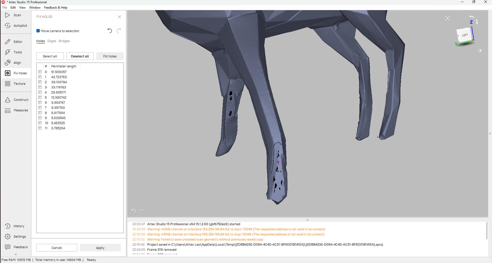
When applying registration, some points outside of the scanned model that was previously invisible became visible and were converted to 3d selections. So we reuse the Eraser tool to remove the unrequired data. Then we use Hole filling operation to see where holes have been formed due to lack of data.
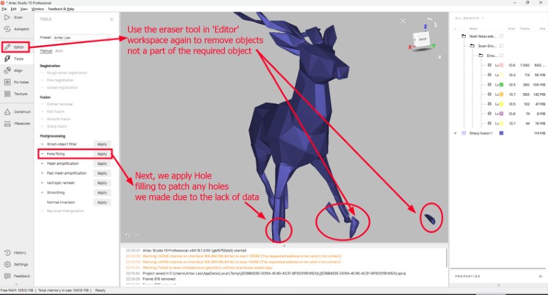
Most of the holes will be created at the legs since I was struggling to capture the data from the legs due to how thin they are compared to the rest of the model.
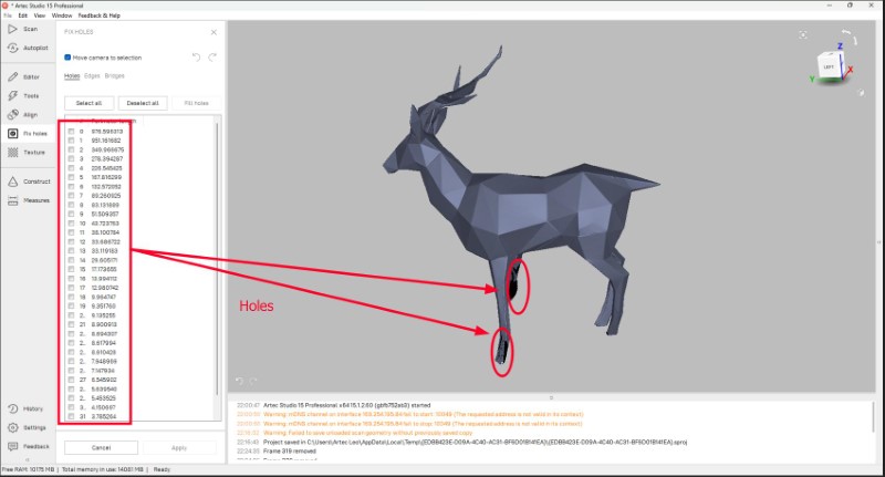
Now we need to select the holes that are related to the 3d model and deselect the rest. But if we remove too many holes, we could end up with unpredictable and undesirable results.
This is how it looks like after I used Fix Holes operation. It is good enough to move to the next step.
Now the last step is to apply texture data. We choose one of the scan groups with the best data and apply it. This step will take a while to perform and is computationally heavy, so there is a chance for the computer to crash, so it is recommended to save the file (unlike what I did) to avoid risking losing all your previous work.
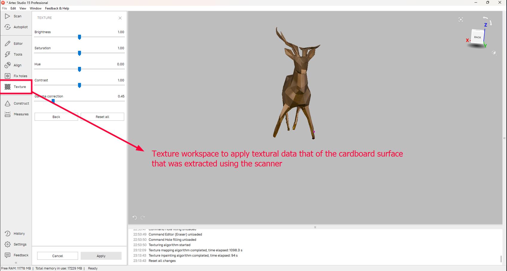
This is what my model looks like after post processing.
The model can be now exported as a STL file to be 3d printed
3D printing the scanned model
This is how it looks like when we import the STL file into Bambu Studio.As you can see there are multiple error messages that will be addressed one by one.
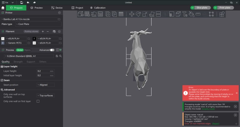
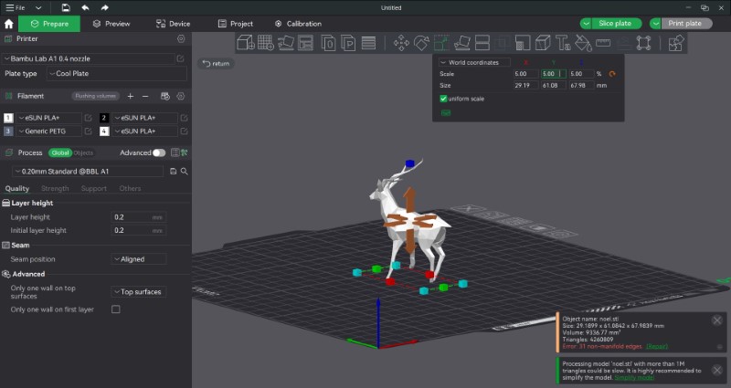
As you can see, since it is an STL file, it is unitless, so we have to manually resize the model so it fits inside the print bed. I adjust the percentages in the dialog box itself to maintain the original proportions.
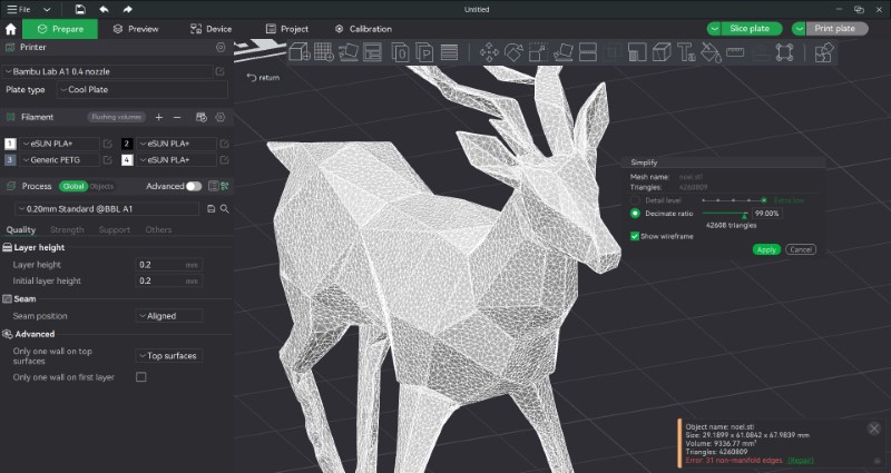
Also, the model is made of more than 1 million triangles, which will slow our slicing by a lot. Such high precision is not required, so we can simplify the shape. I specified the decimate ratio since setting detail level at extra low does not simplify the model enough.
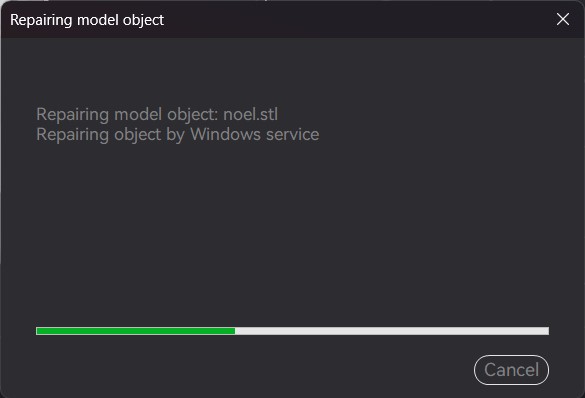
Then I press on 'Repair' to repair the 3d model.
While waiting fot repairing to finish, I read up on what non-manifold edges mean. From this article, manifold edges mean that each edge of a 3d model should be connected to exactly 2 polygons. When the edge is connected to more than 2 polygons (overlapping faces) or less than 2 polygons (holes), it is called non-manifold geometry and the edges are called non-manifold edges.
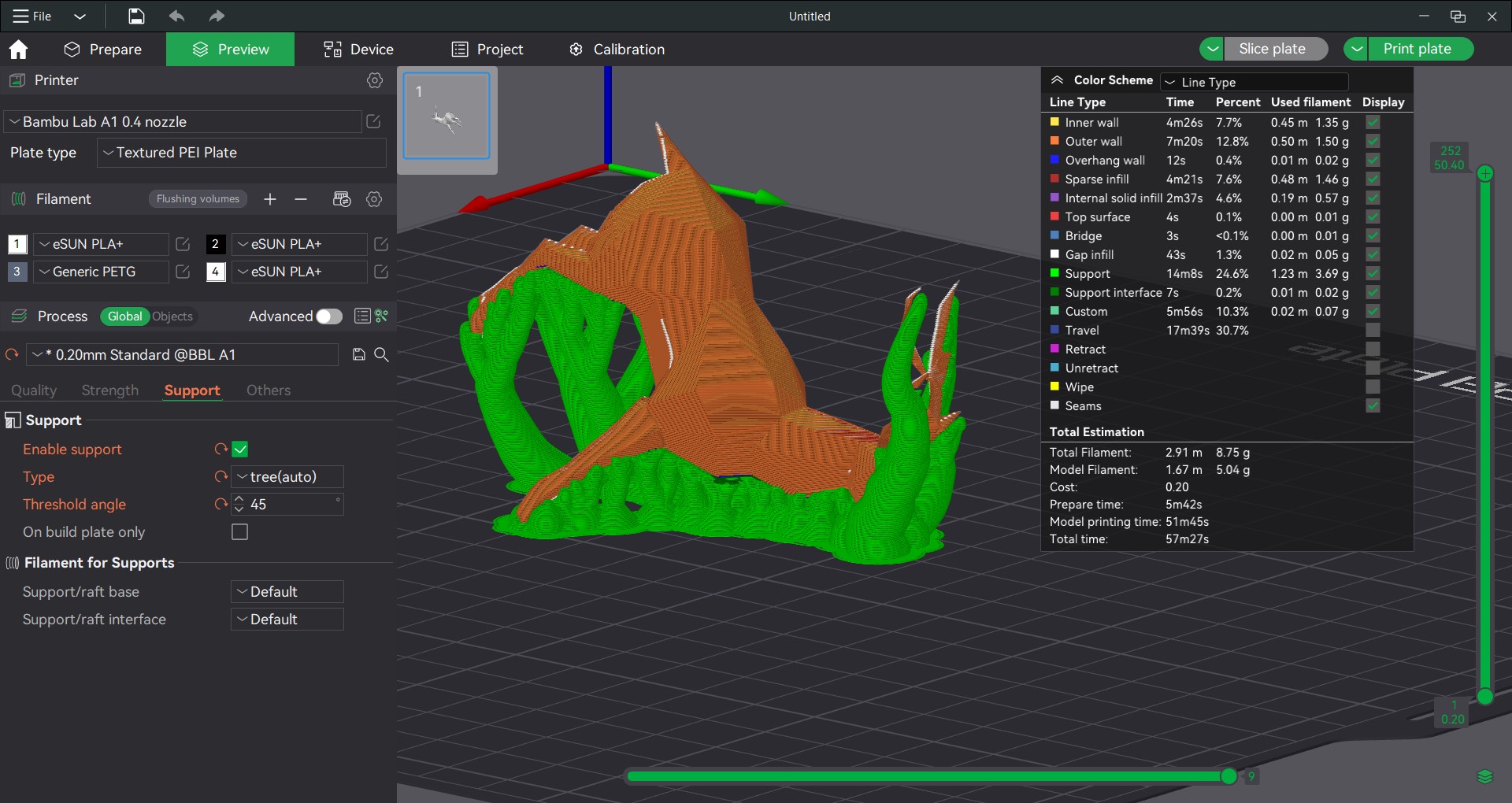
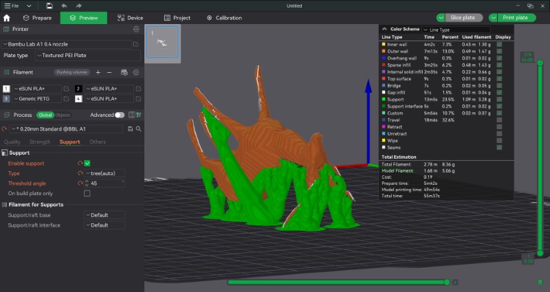
Once repaired, then we slice the model. When we do that I see that there is a warning message warning us there are floating regions, ie. regions with no support below it that require additional supports.
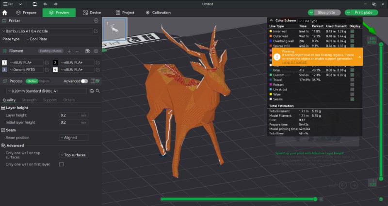
I then enabled supports, checked the box for automatic tree type supports and increased the threshold to 45 degrees based on test results in our group assigment.
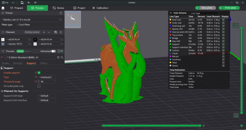
As you can see there is a lot of support material being used, so I used the Auto Orient feature to figure out a better orientation.
Based on instructor feedback, the face of the deer would lose texture because of the supports and post processing involved in removing them. So I experimented with a different orientation
But the problem exisit here also, so I reverted back to how it was originally
Conclusion
This week I designed and printed print-in-place joints that are difficult to make surbtractively. Also I learnt to 3d scan using the Artec Leo
References
Resources I refered while making this week's documentation
- Week 5 Group Assignment: Test the design rules for your 3D printer(s)
- FreeCAD creating a print in place hinge - Fully Parametric ( Adventures in creation)
- Print in Place Hinge in Fusion 360 (Desktop Makes)
- Slicer Settings for Print in Place Phone Stand(Desktop Makes)
- Bambu Lab Cool Plate (Bambu Lab)
- Automatic Material System (Bambu Lab)
- Artec Leo 3D Scanner (Artec 3D)
Design Files
- Click here to access the design files of this week.