3. Computer Controlled Cutting
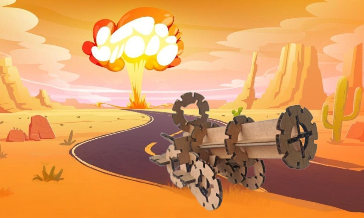
This week's assignment tasks are listed below:
- group assignment:
- do your lab's safety training
- characterize your lasercutter's focus, power, speed, rate, kerf, joint clearance and types
- individual assignment:
- cut something on the vinylcutter.
- design, lasercut, and document a parametric construction kit;
- accounting for the lasercutter kerf
- which can be assembled in multiple ways
- and for extra credit include elements that aren't flat
Work Plan
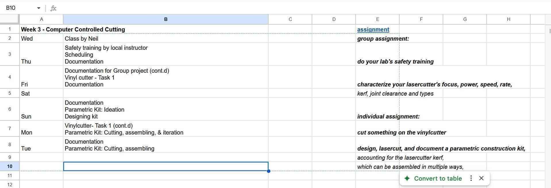
I experimented with ways I can increase my productive hours. I really like how Adrian Torres (Fab Academy 2020) plans his work on an excel sheet & I wanted to try the same.
3.1 Group Assignment: Laser Cutting
As part of the group assignment, I participated in the laser cutter safey training and learned to test for material thickness, kerf, and adjustment for a tight press fit
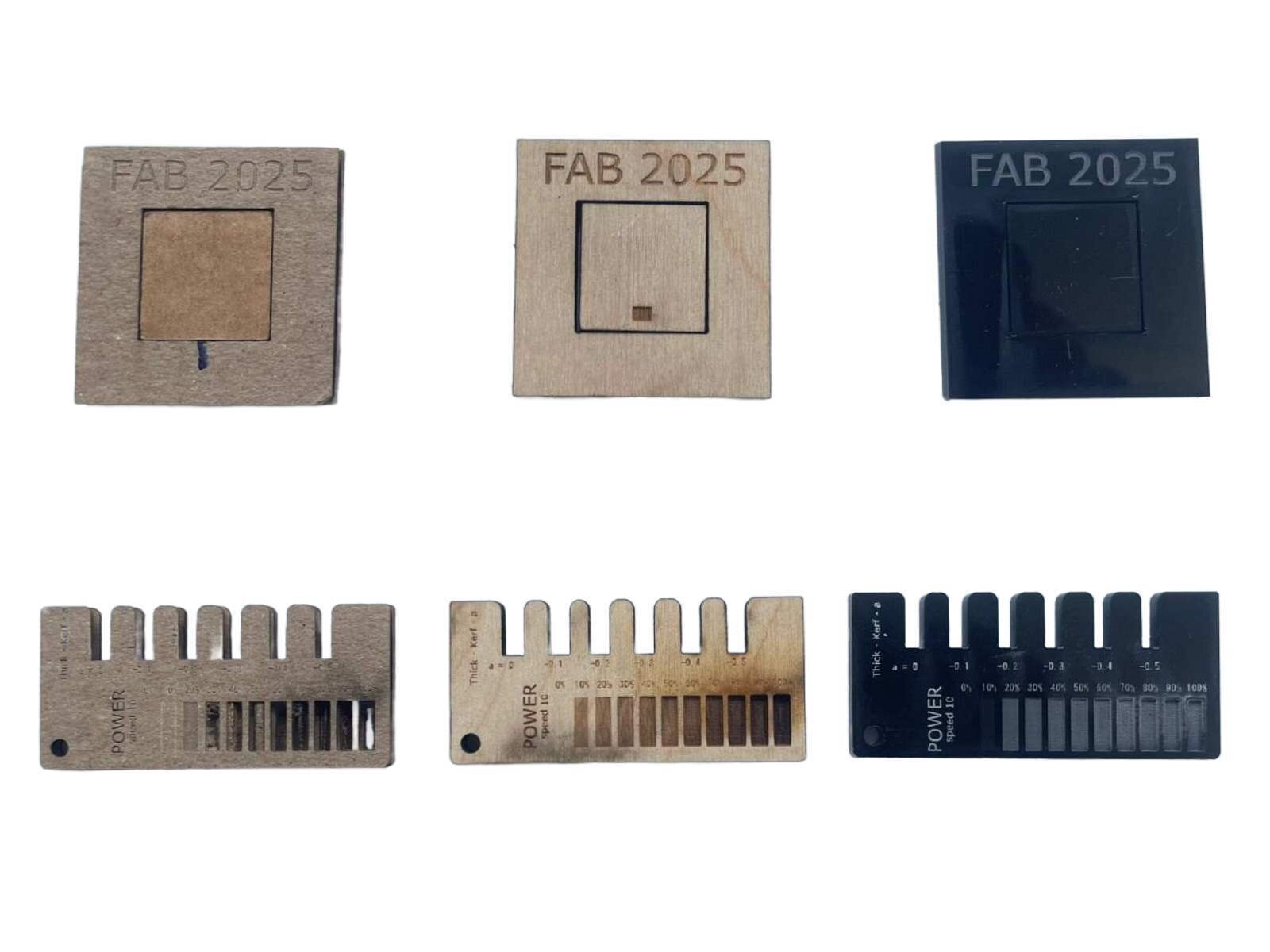
Here are the readings

We tested for compression by fitting it in grooves that become progressively smaller sized by 0.1 mm.
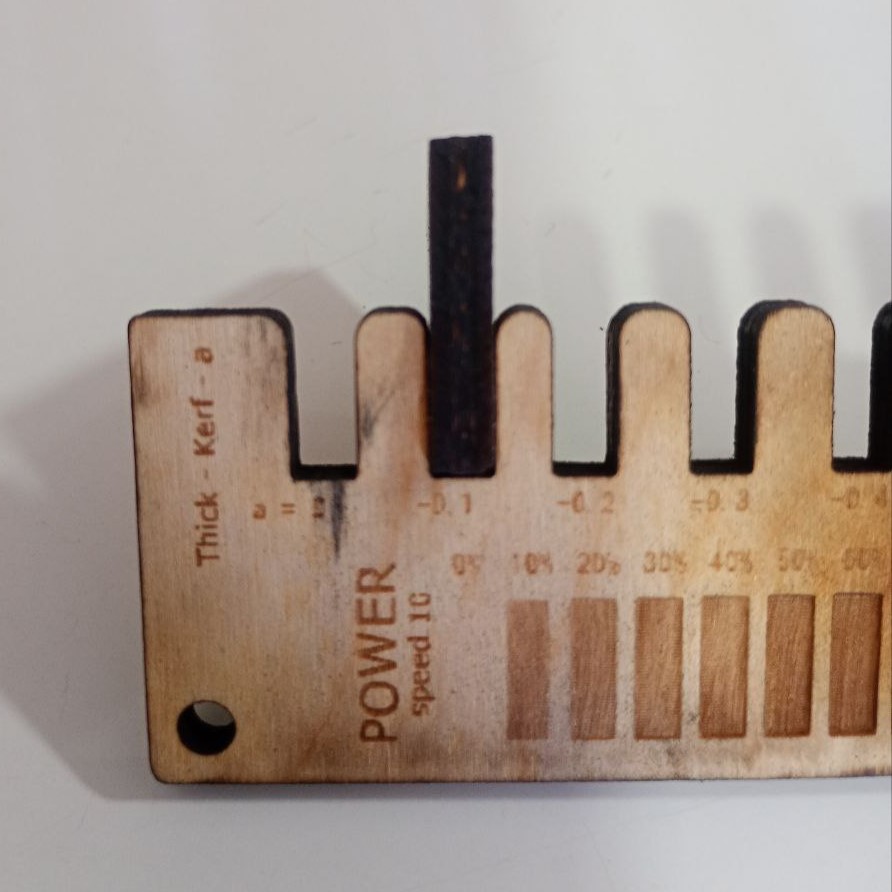
These are the parameters we used for cardboard.
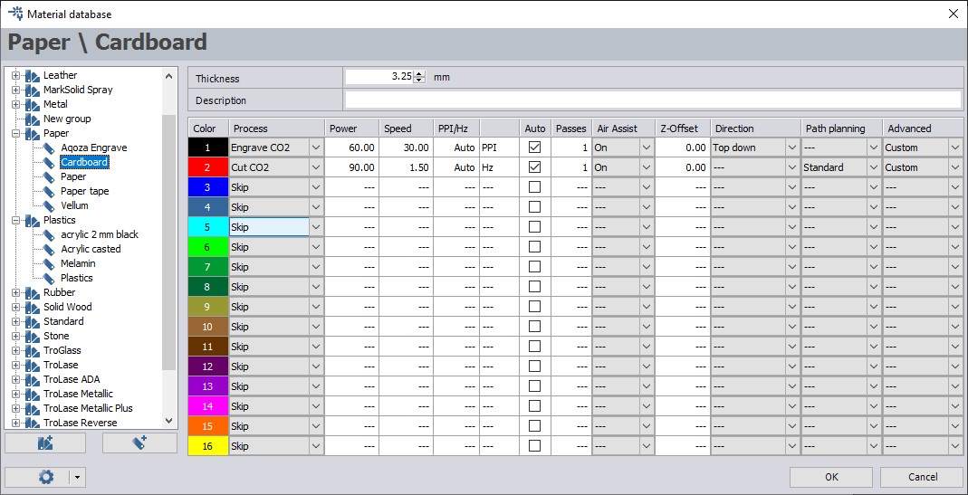
Based on our experimentation
- For Engraving: We used Power-60%, Speed-30 %, Passes-1
- For Cutting: We used Power-90%, Speed-1.50 %, Passes-1
You can read more about our group assignment here.
3.2.1. Individual Assignment: Vinyl Cutting
Vinyl cutting is a process of cutting patterns into vinyl sheet to create patterns and stickers of different sizes. The machine we are using is a Roland GX-24 GS-24. It has an pen whose depth can be adjusted and whose bit can be replaced. Movement of motor and pen head in the X axis & Y axis movement of vinyl sheet together help cut shapes in one plane (XY) plane.
.jpg)
Making a vector image in Inkscape
Inkscape is a free vector graphics editor. To download click here. Used basic shapes to make a clown face.
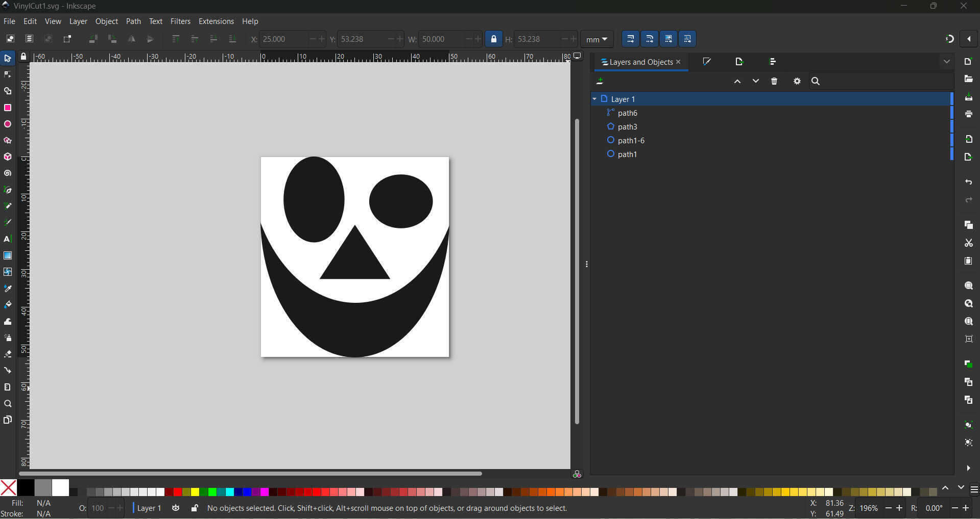
A possible mistake is not adding enough white space around your shapes might prevent the machine from making a full cut.
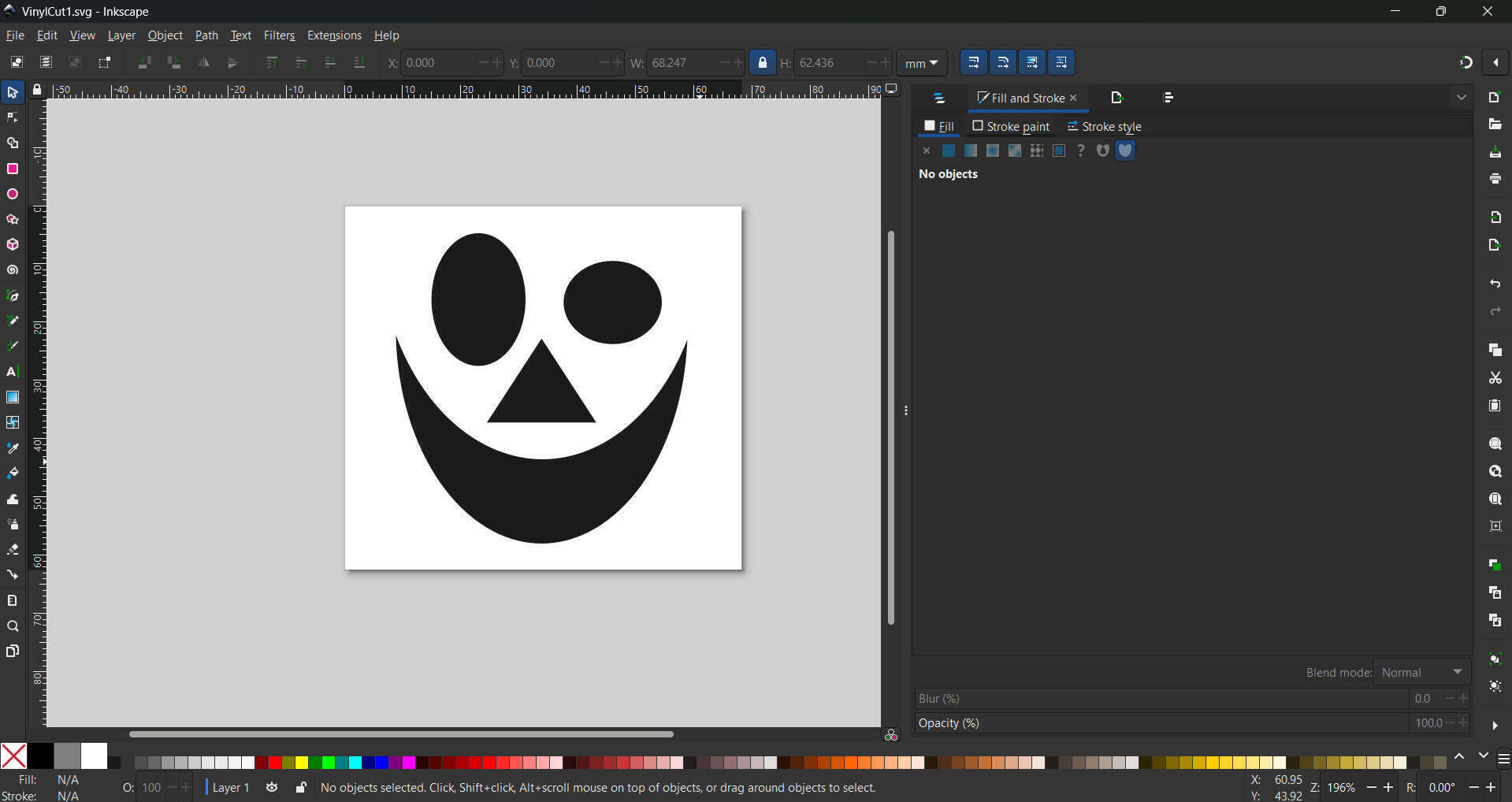
I wanted to try cutting two different colors to make this image of a clown.
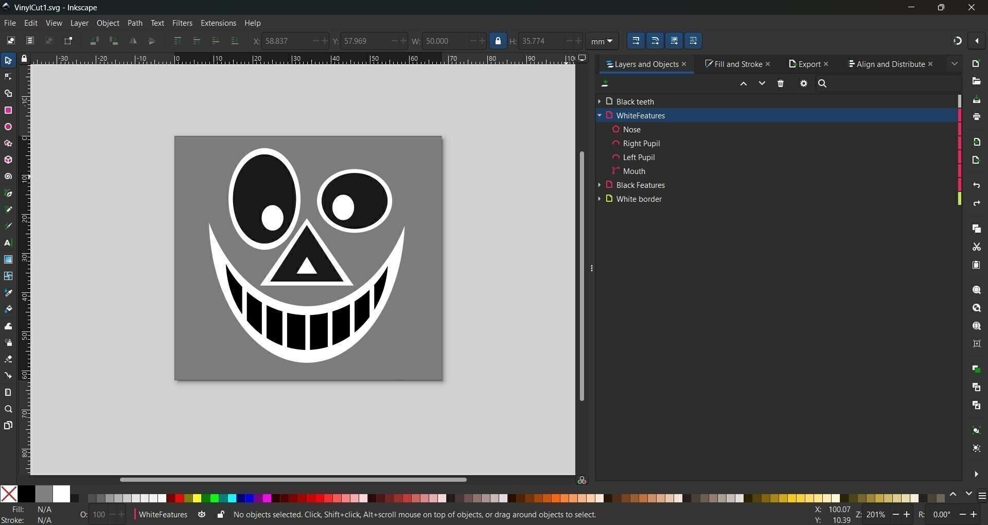
The black and white features will be printed seperately on seperate svg files. Since the vinyl cutter uses contrast to figure where to cut, I first convert all the white features to black with fill operation to which will then be cut on white vinyl sheet.


Operating the Vinyl Cutter
.jpg)
- Select the vinyl roll you require and place it on the rollers behind the vinyl cutter.
- Open the lever by pushing down on it, which will unlock the clamp allowing you to feed the vinyl sheet.
- Add the vinyl sheet, set the rubber wheels at each end of the vinyl sheet to set the position. The wheels should only be adjusted from behind the machine.
- Pull up lever to secure the roll in place.
- Push on the on switch to turn on the vinyl cutter. Select 'roll' and then 'enter' and the vinyl cutter will start measuring the vinyl sheet.
- Adjust the pen to a point from where it can start the cut operation and select 'set origin'.
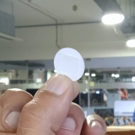
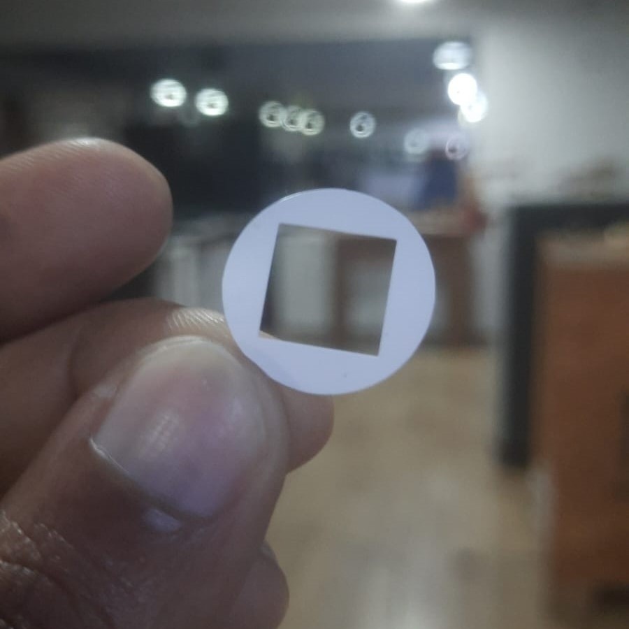
- We also need to set the required force, speed and depth. To test this we use a test cut. A good cut is when the outer circle peels off when we pull but the inner square does not come out with the outer circle
- After some experimentation the settings that worked for us were 100 gf and 1cm/sec.
-
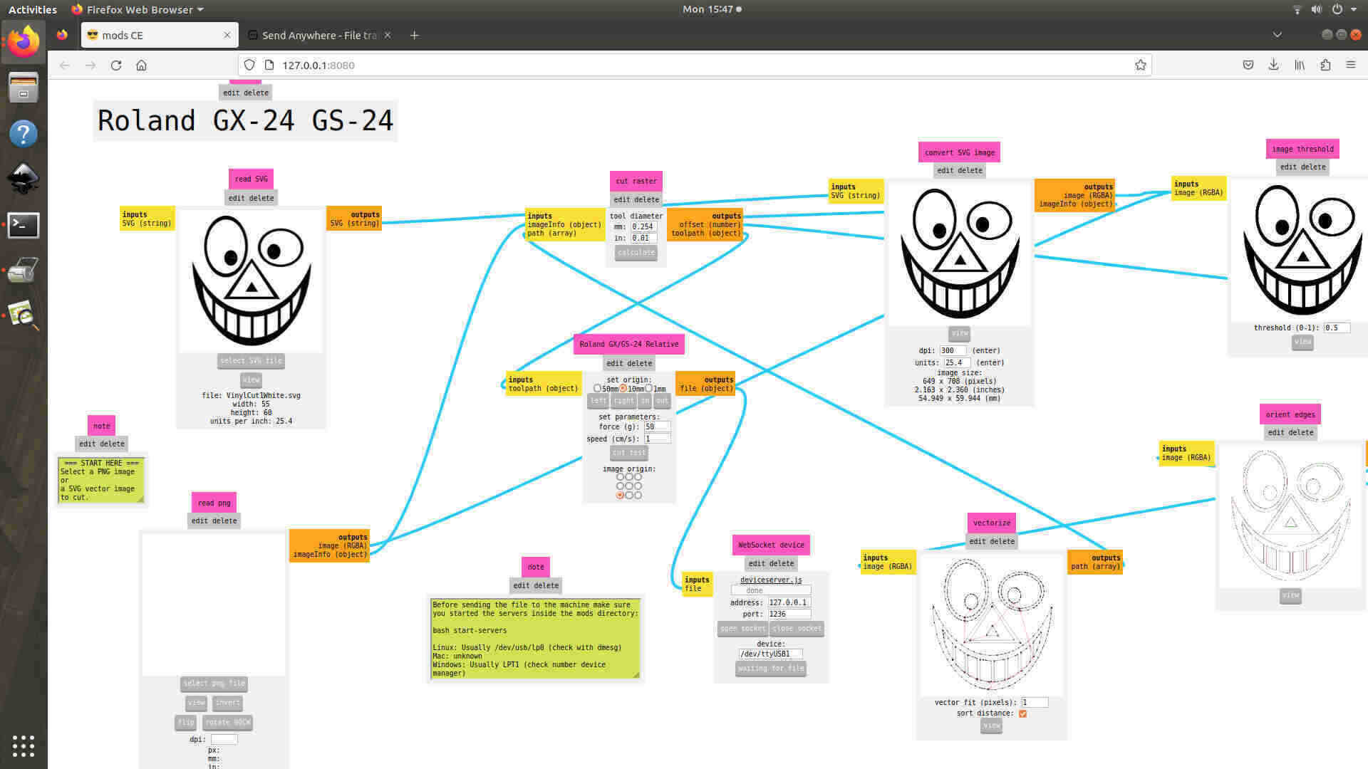
We use an open source tool called ModsCE to control the vinyl machine.
ModsCE (Community Edition) is a cross platform tool first developed at MIT, the idea being you should be able to control multiple machines using one tool/software. At our fablab, We use ModsCE to control the vinyl cutter and PCB milling machine.
You can read more about ModsCE here here.
This is the link to the tool.
We insert the svg file, adjust the speed (force parameter does not work, we have to set it in the vinyl cutter), press 'calculate' and press 'send the saved file' to start the operation. We press 'calculate' and 'send the saved file' every time we adjust some parameter before cutting.
Cutting and Pasting as a Sticker
Using tweezers and a blade, I cut the designs from the vinyl sheet backing and transfered them onto my phone case. I tried to use the transfer tape to align the sheet but it was too hard because it was not transparent enough and I was not able to see the black shapes because colour of the phone case was the same.
When designing I was not thinking about where I will be pasting the image and hence didn't choose my colours properly, so I endedup sticking black vinyl on black phone case. I thought maybe the viewers would be able to see the difference because of the difference in texture between my phone case and sticker but it did not work out the way I hoped.
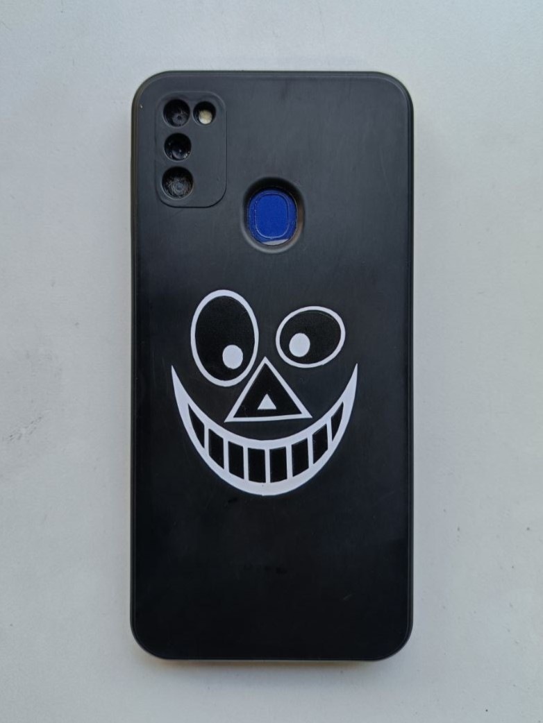
I think it would have looked better with red and black

3.2.2. Individual Assignment: Parametric Construction Kit
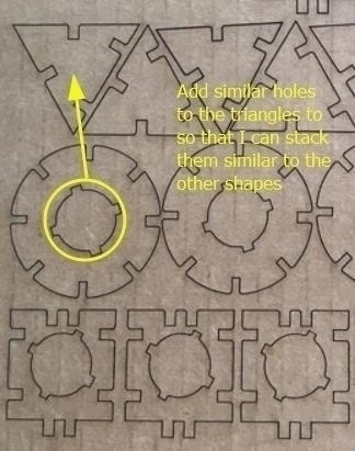
I was very impressed by the modifiability of a parametric construction kit made by Akhila (Fab Academy 2018) who who made this design based of a design made by a previous Fab Academy student. I wanted to use the same basic design but with some small modifications.
- Add a hole to the triangle piece in case I needed to stack it on one axis
- If time allows, I wanted my model to be able to rotate with minimum possible pieces, I tried adjusting the rectangle sizes, bit since they kept getting getting caught in the groove, i abandoned the idea and decided to make a larger circle with a larger inner diameter and no grooves to allow axle rotation.
- If time allows, add creased cardboard parts with creases along the flutes to allow for bending both ways in the same plane
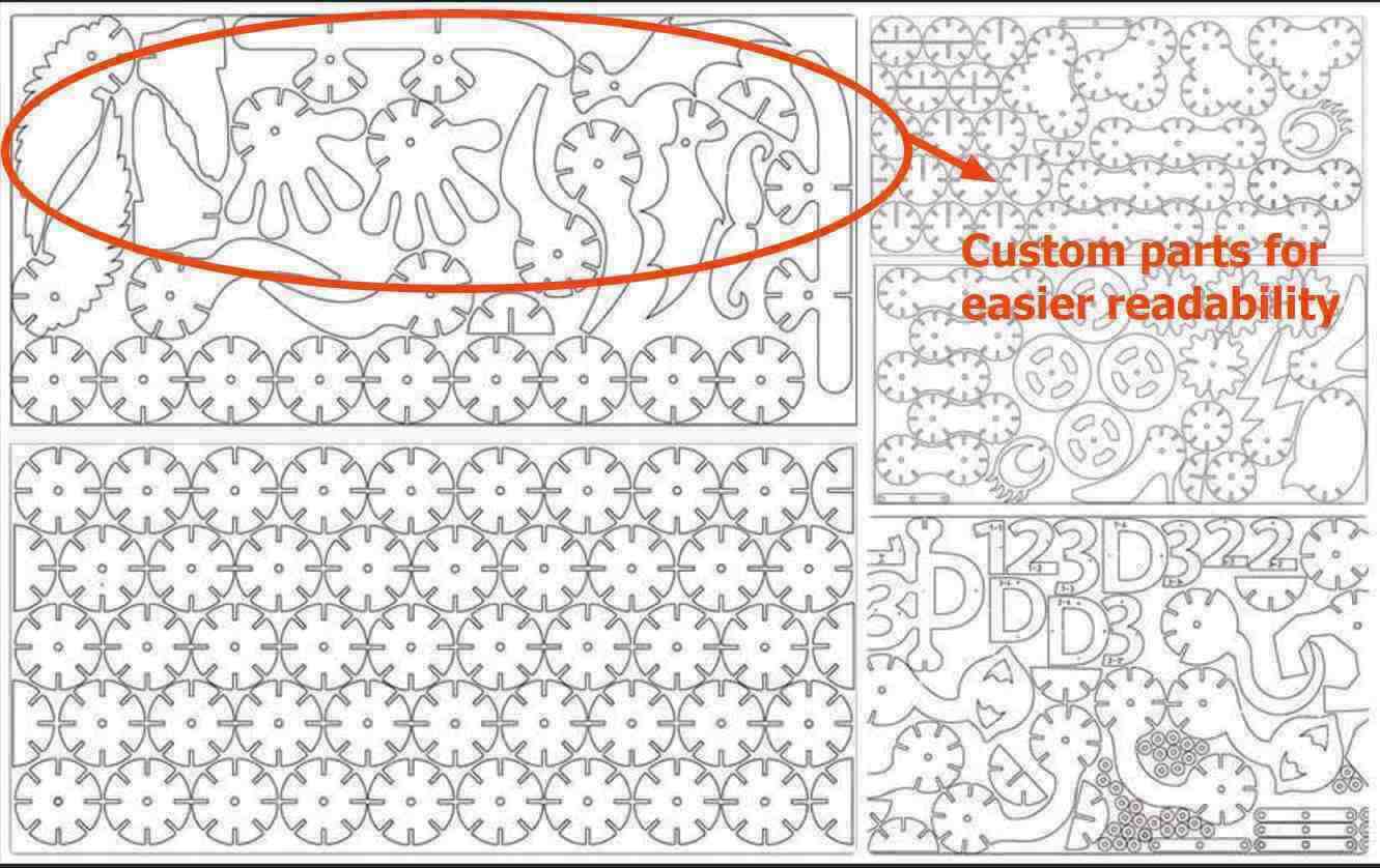
- If time allows, add custom parts to make it easier to recognise characters just like this design called 123D Fab
- Maybe even make these pieces two or three different size modifications to aid in making more complex features
CAD Design
The first step is to make a parametric sketch. There are three main parameters that we used:
- Material Thickness (MatThick): Thickness of the material we are using, ie. cardboard = 3.25 mm
- Kirf: The width of the area that is removed by the laser beam in the process of cutting = 0.23 mm
- Press Fit Adjustment (PFit_Adjust): Decides how tight or loose our fit will be = -0.2mm
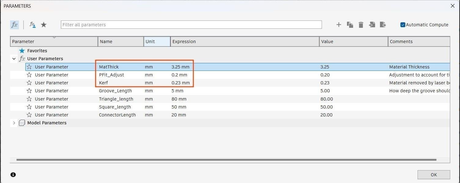
Apart from that I have added parameters for many other dimensions like groove length, edge length for each shape, etc with the idea that I can change them at a later date without breaking the geometry every time.
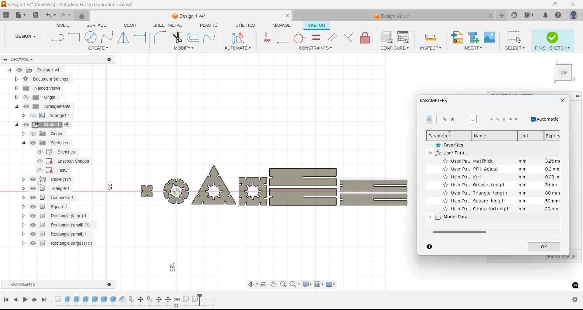
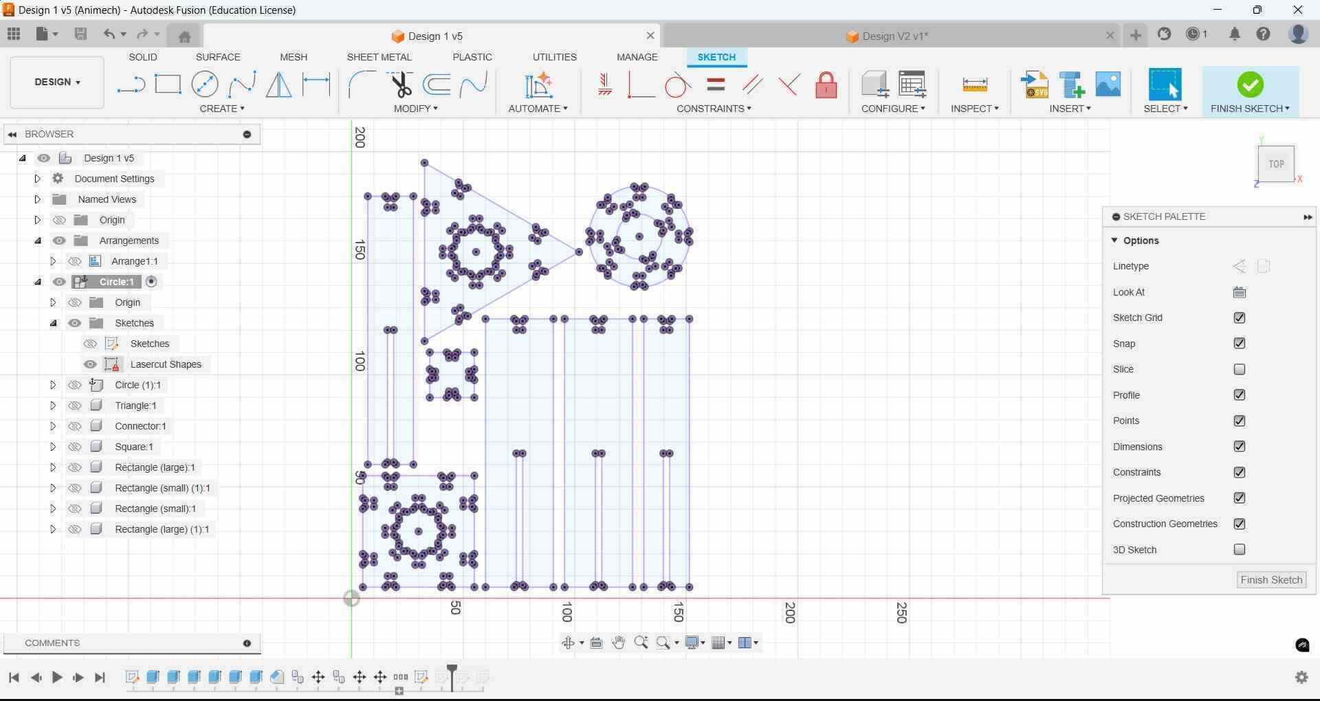
I then use the Arrange feature to arrange all my shapes (which I have moved to individual components) such that it takes up minimum space. I then project the faces to a new sketch that we then export as a DXF file.
Laser Cutting
Different cardboard sheets can have differences in thickness and very small differences in kerf, so we always make a test cut and test the joints once before making multiple copies. It also helps us find flaws in our design without wasting material. We figured out parameters through the group assignment

One point to note is that when working with cardboard there may be bends in the cardboard that cause it to not stay flat on the cutting bed. Very large bends can be problematic because the laser is not hitting all the points of the the cardboard sheet at its focal length where you get the sharpest cut. Masking tape can solve this problem for small bends.
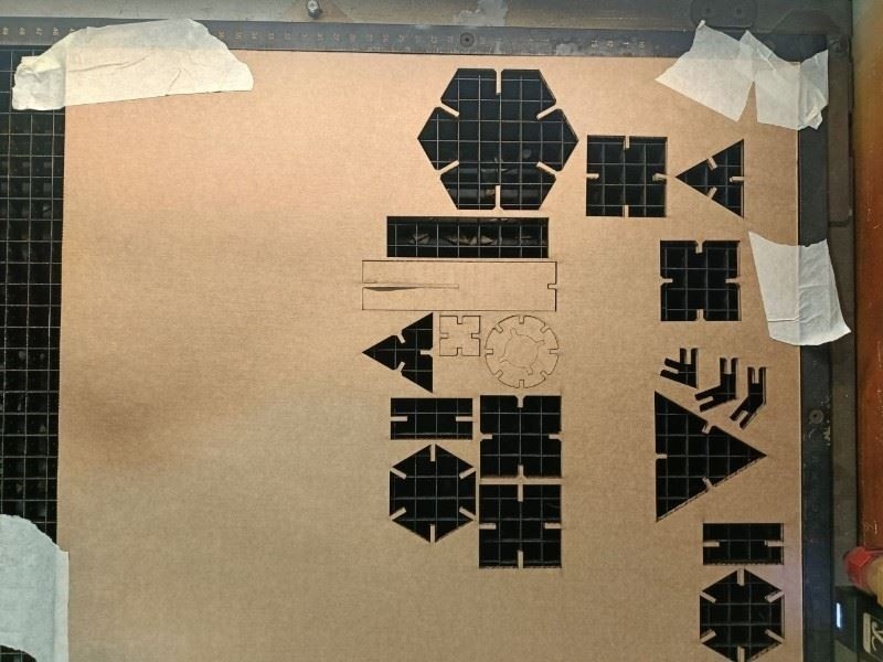
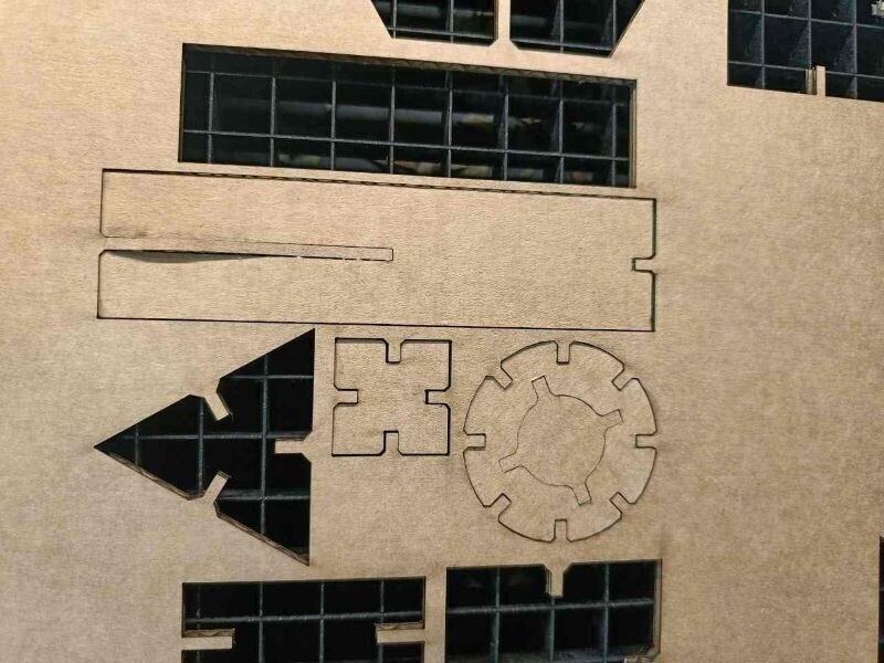
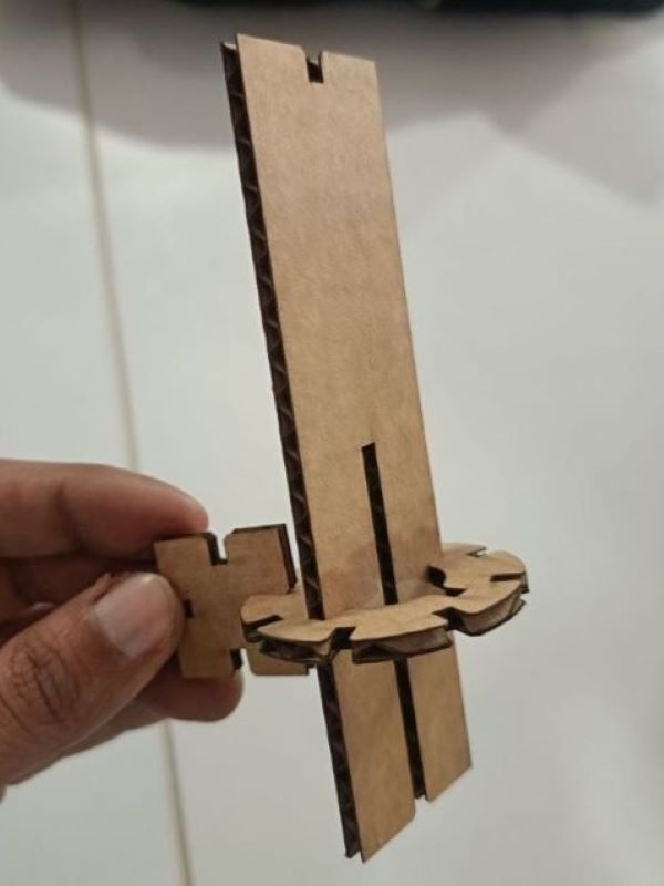
After we have confirmed the fit of our test pieces, then we cut out multiple copies
Iterations
- Iteration 1: No chamfer, which makes it harder to insert pieces. Also, the lengths of rectangles do not match the holes.
- Iteration 2: Chamfer of 1mm added. The width of the rectangle pieces is made equal to length of groove using equations
- Iteration 3- Increased number of inner grooves to increase number of possible orientation. Add space between inner groove and outer groove to allow for multiple pieces to fit at the same time, Length of rectangle adjusted again.
- Iteration 4- Currently, rectangles cannot be used for free rotation. Instead of making duplicate copies of all other shapes with larger holes I made a new rectangle shape of smaller width to allow free rotation. Also made new smaller connector to connect large shapes in the same plane. Got the idea from playing around with the waste that was left behing from cutting out the internal holes in all the shapes
-
Iteration 5- The smaller rectangles do not allow for free rotation because they keep hitting the inner grooves. Since I was losing time I postponed the idea for later once I completed the assignment.
I wanted to make the the connectors small to differentiate them from the other designs. To do this, I designed the piece such that that the inner groove was only 2.5 mm long, half the length of the grooves of the other pieces. However, this iteration was a failure since the smaller grooves allowed the bigger pieces to wiggle around, resulting in a weak joint.
- Iteration 6- The number of individual pieces were now becoming too many, so I simplified my design by only choosing the circle, the rectangle and the connector. I made the connector piece larger and the groove length 5 mm.
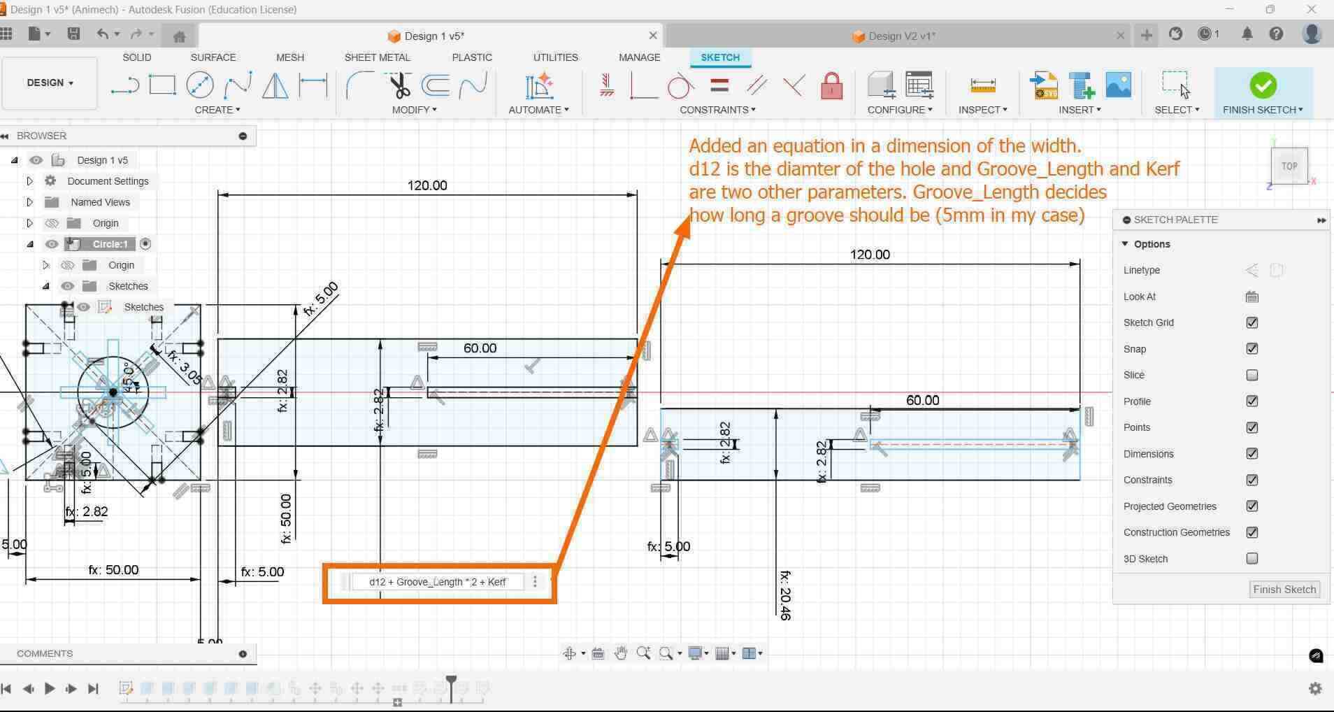
Note: Based on feedback given during local review, parameterised the equations also
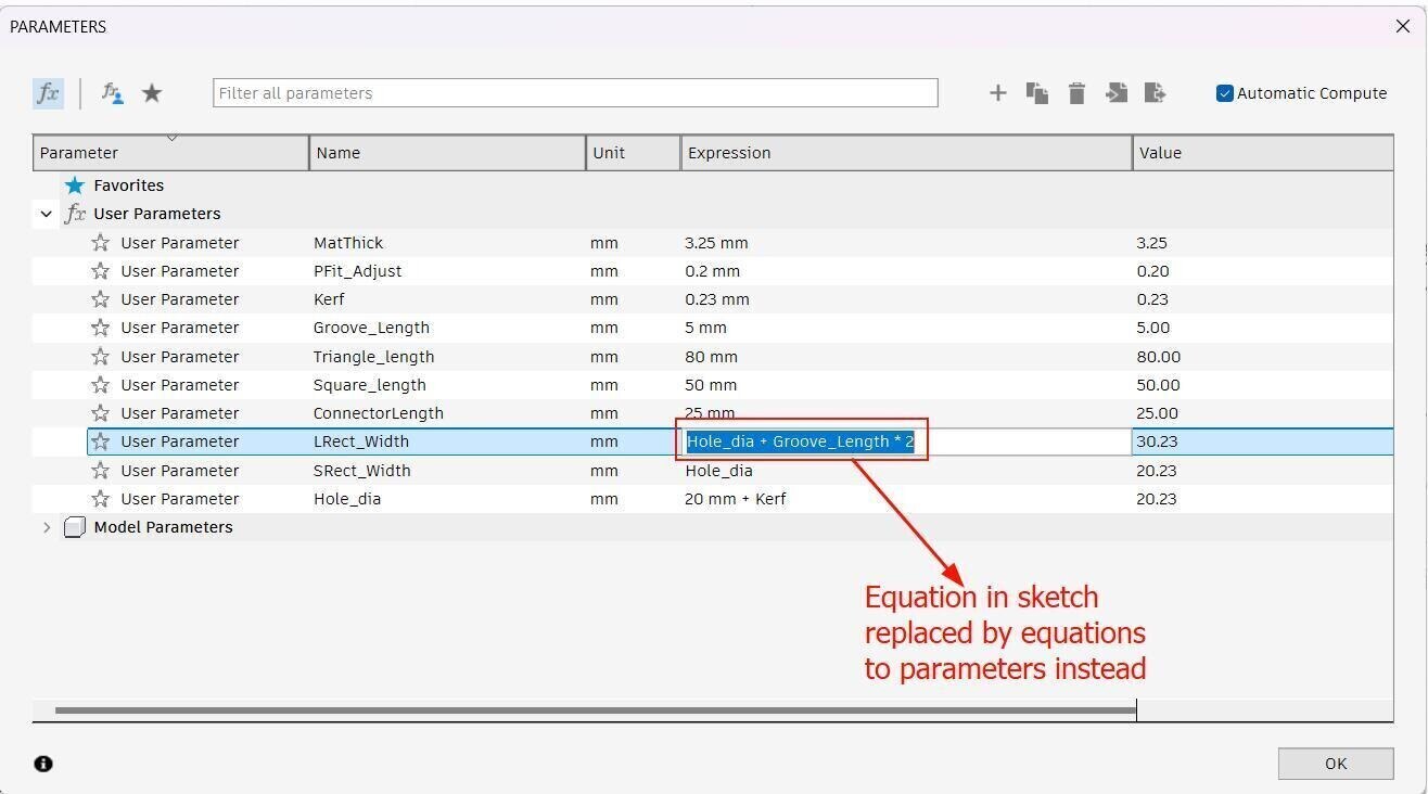
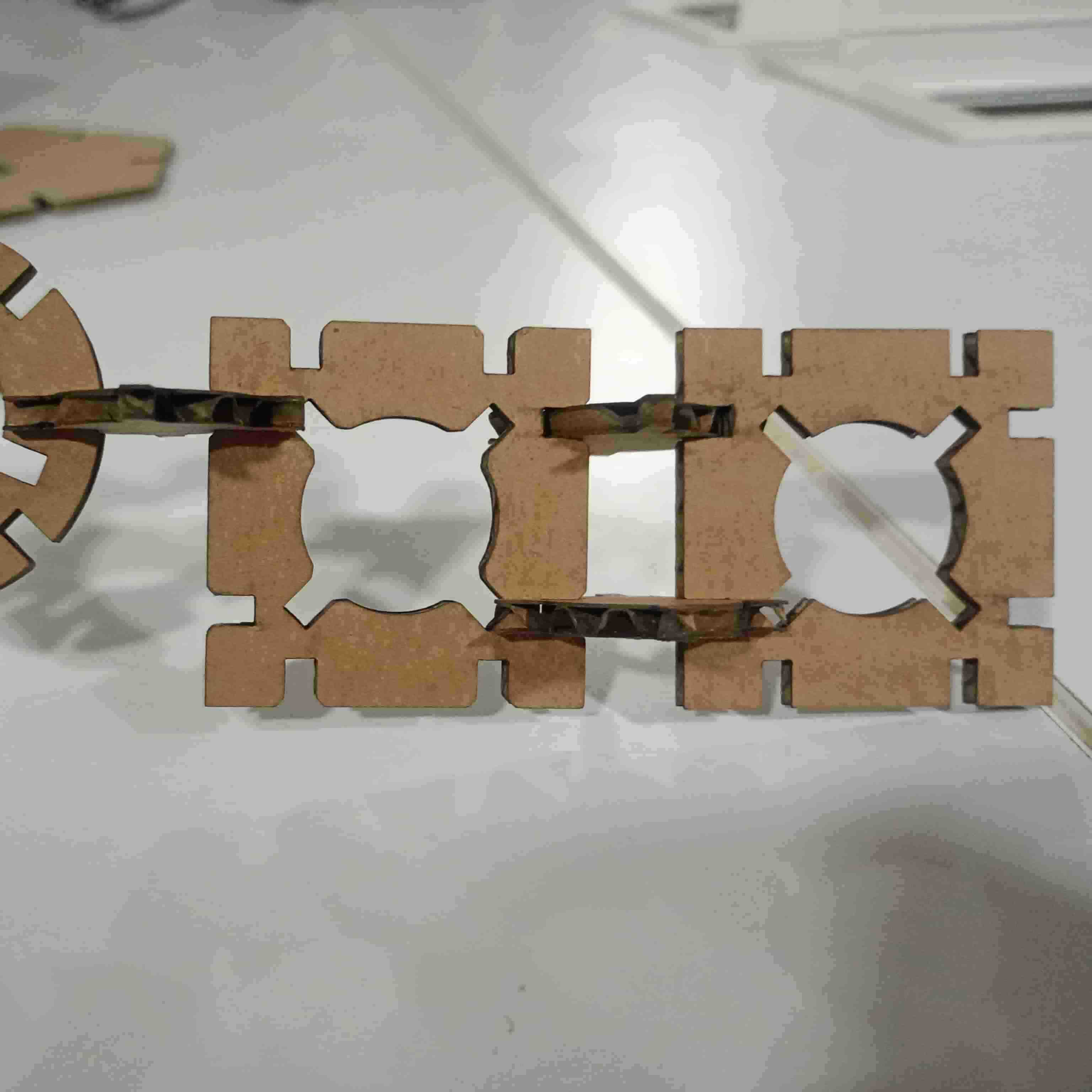
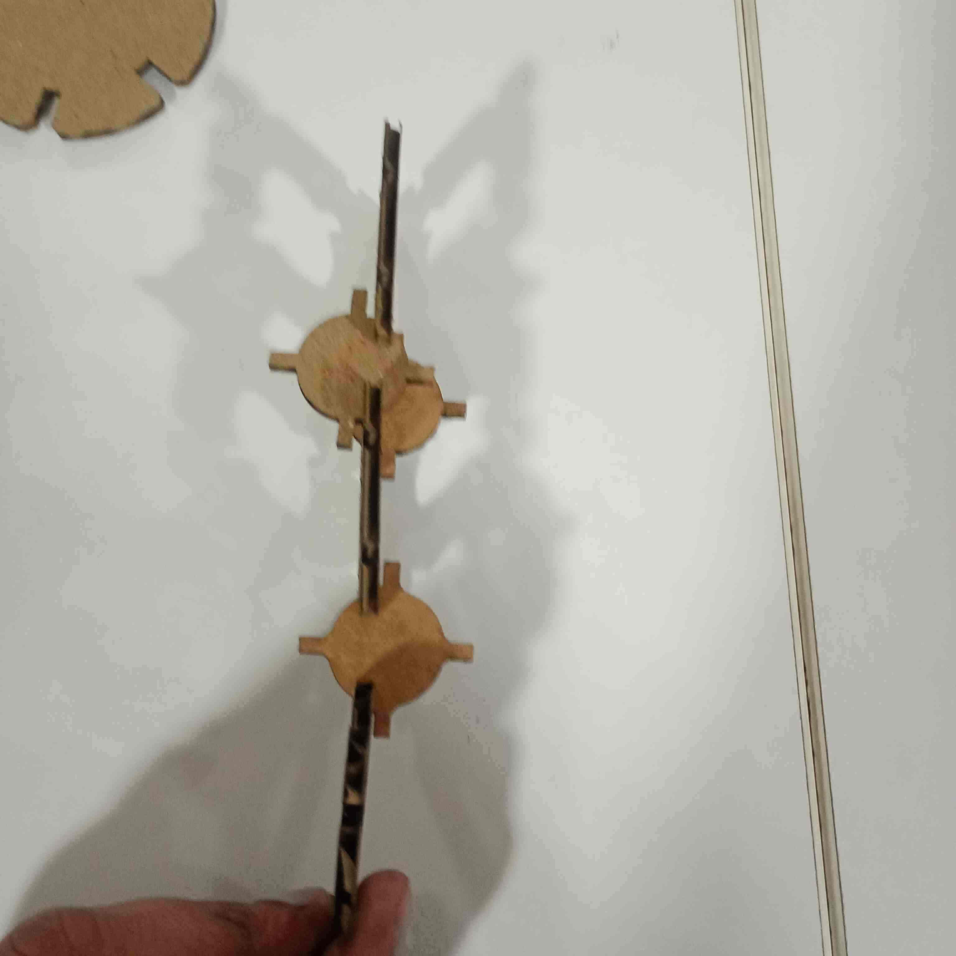

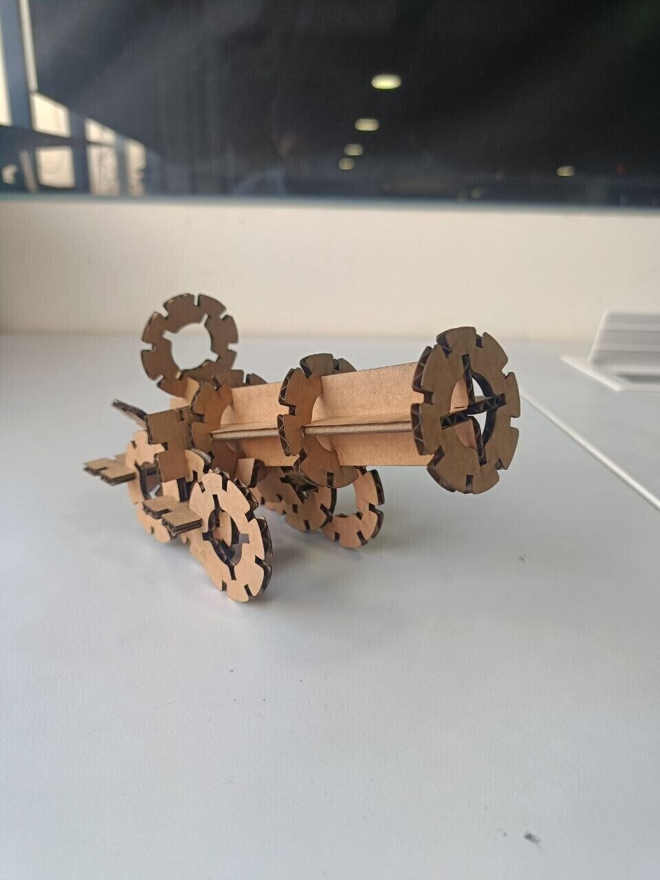
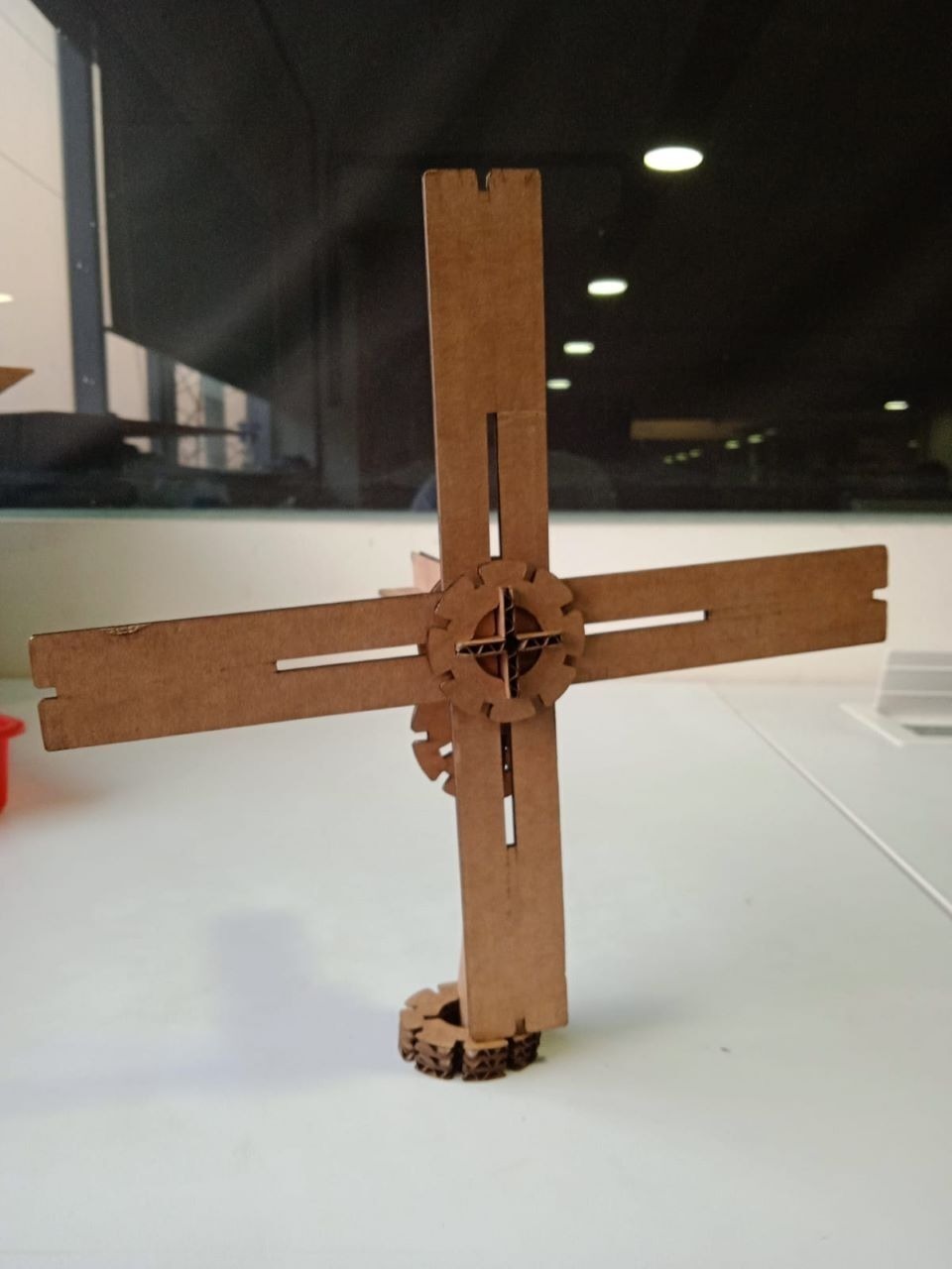
Assembled models
Cannon
Merry Go Round
Windmill
Metal Engraving
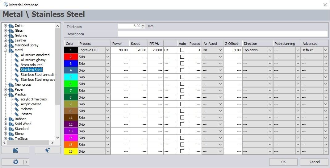
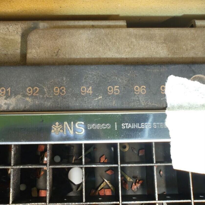
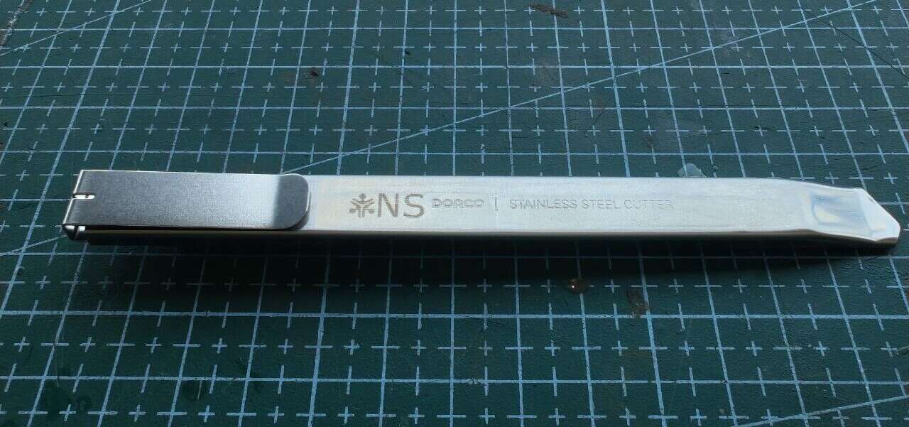
Since I had some free time, I was suggested by Saheen Palayi, our instructor, to try using metal engraving, since our laser cutter, the Trotec Speedy 400 flexx has both CO2 and fiber lasers. We have been using the CO2 laser so far for our parametric kit, whereas the fiber laser is required for cutting and engraving on metal. I decided to label my blade using the fiber laser
Firstly, I measured the dimensions of a section of the surface of my bade using a vernier calliper. I then went to Inkscape and made a vector image of the Fab Kochi lab logo that I vectorised using the Trace Bitmap feature, followed by my initials. This time we remove any strokes, instead adding a black fill that we have preset for engraving.
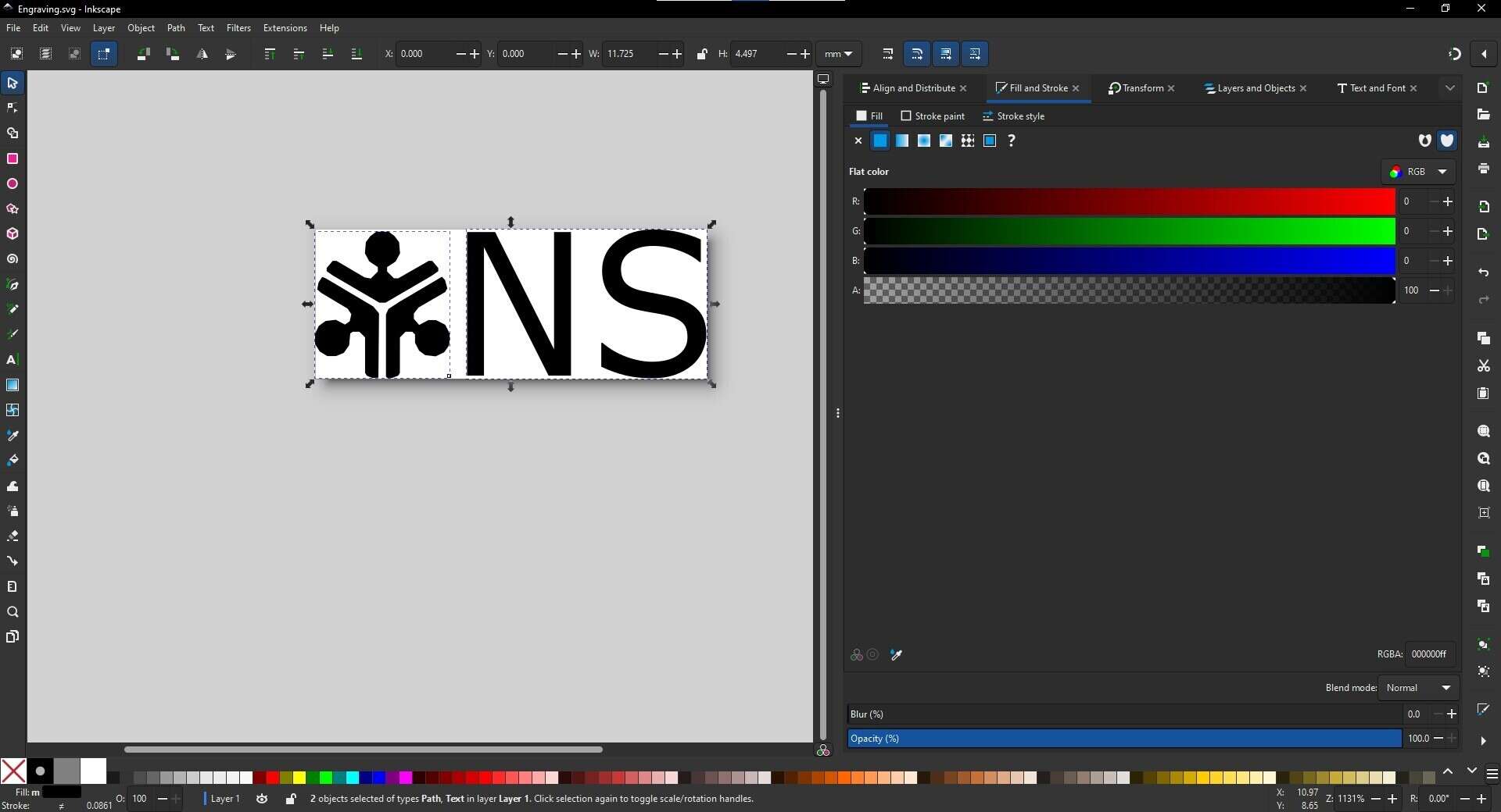
I taped the blade onto the bed to avoid any possible shaking. Also I used the key to manually focus the laser head, because at such small widths, the autofocus might not work reliably.
.jpg)
I have to ensure our parameters are set correctly before engraving.
This is how it looks like after engraving
Conclusion
In this week, I learnt to use laser cutting to cut cardboard, wood and acrylic, including kerf and thickness calculation. Additionally, I learnt to engrave on metal. I also learnt to use viny cutting to cut my designs as stickers and parametric design using Fusion CAD software.
In terms of time management, using the Pomodoro technique seems to be effective, but I need more practice in executing on projects that are 'just good enough', instead of making it closer to 'perfect'. Planning your workweek is good, but only if you are realistically able to meet project deadlines and try your best to complete the tasks you have assigned for the day.
References
- Free vector image I used for the hero shot (Freepik) and edited in Photopea
- Work week planning by Adrian Torres (Fab Academy 2020)
- Group assignment Fab Academy 2025
- Parametric Construction kit made by Akhila Surendran (Fab Academy 2018)
- 123D Fab Cardboard Construction Kit
- Trotec Speedy 400 flexx, the laser cutter we used.