week15. System integration
Assignment
Individual assignment
- Design and document the system integration for your final project
Individual Assignment
For this week’s assignment, I worked on integrating the PCB and 3D-printed enclosure for my final project. This process included the following steps:
1. PCB Design
To enable system integration, I designed a custom PCB using Fusion 360 tailored to the final project.
The board includes headers for connecting sensors, power input, and communication pins.
Design Process
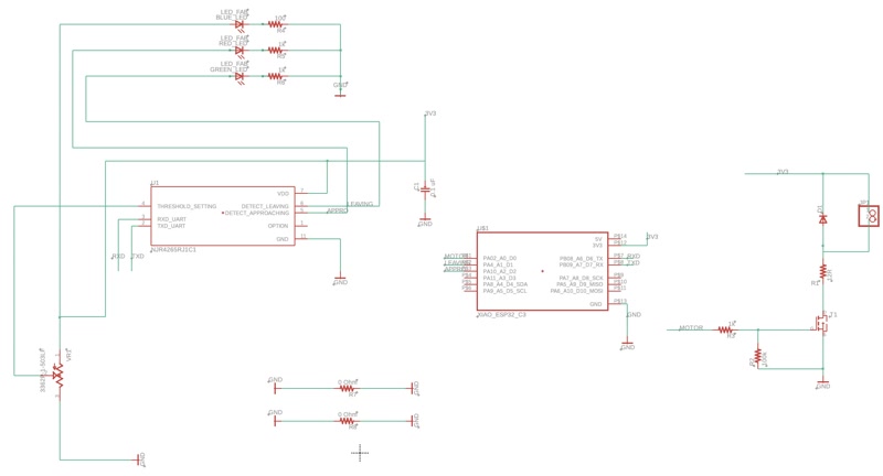
- Circuit Schematic Design
I first created a circuit schematic in Fusion 360 and placed key components such as:
- ESP32-C3 microcontroller
- 24GHz motion detection / Doppler radar sensor module
- Transistors
- Resistors and capacitors
- Pin headers for external motor connection
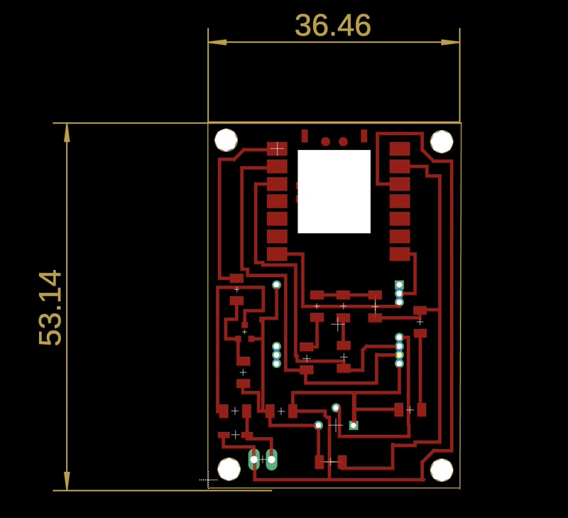
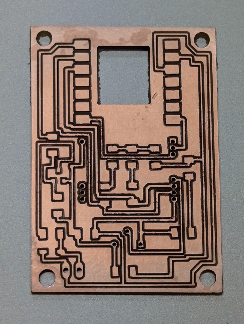
- PCB Layout
After completing the schematic, I moved on to the PCB layout.
- I routed the traces carefully to avoid interference.
- I added mounting holes to match the design of the enclosure.
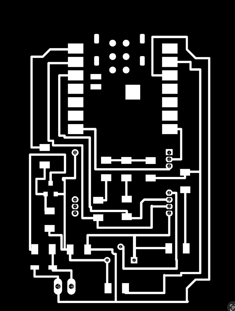
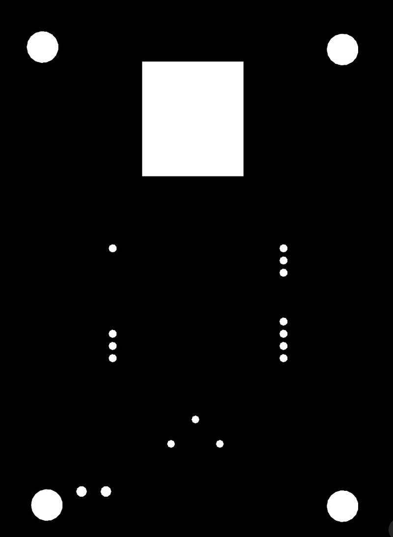
- Exporting PNG Files
To fabricate the PCB using a CNC milling machine, I exported the following files:
traces.png: for milling copper tracesmillholes.png: for drilling component holesoutline.png: for cutting the board outline

TIP
- All traces were verified using Design Rule Check (DRC).
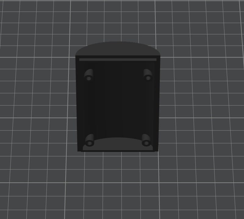
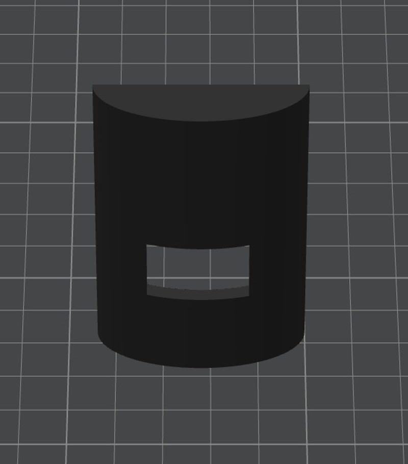
2. Enclosure Design
I modified the 3D model created in week02 to accommodate the PCB.
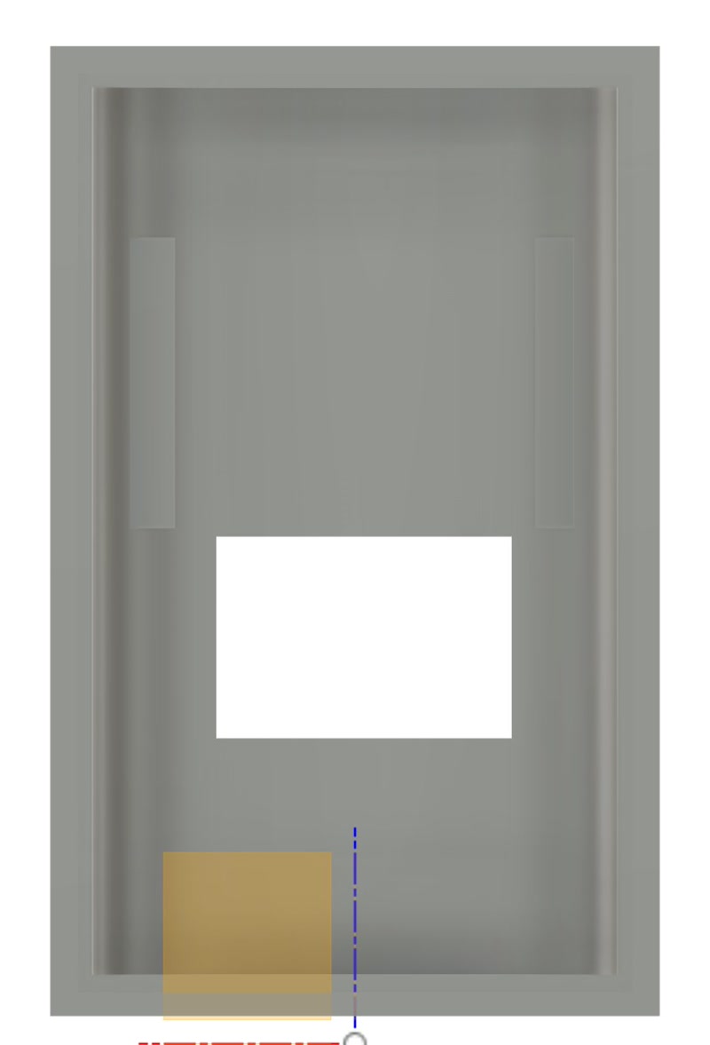
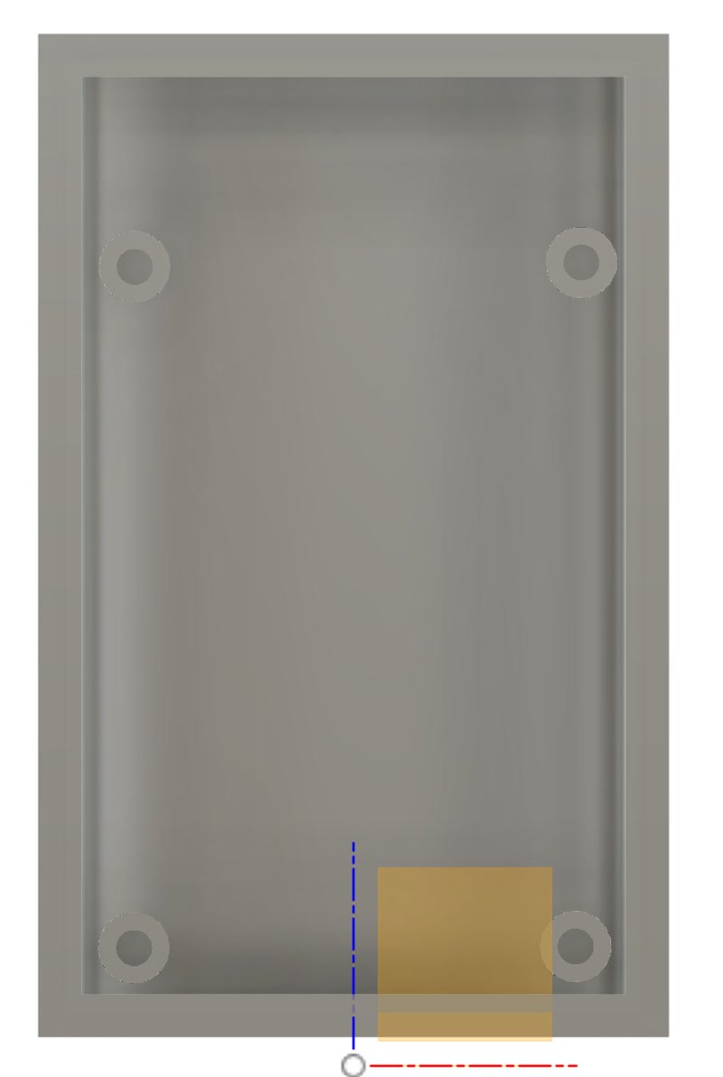
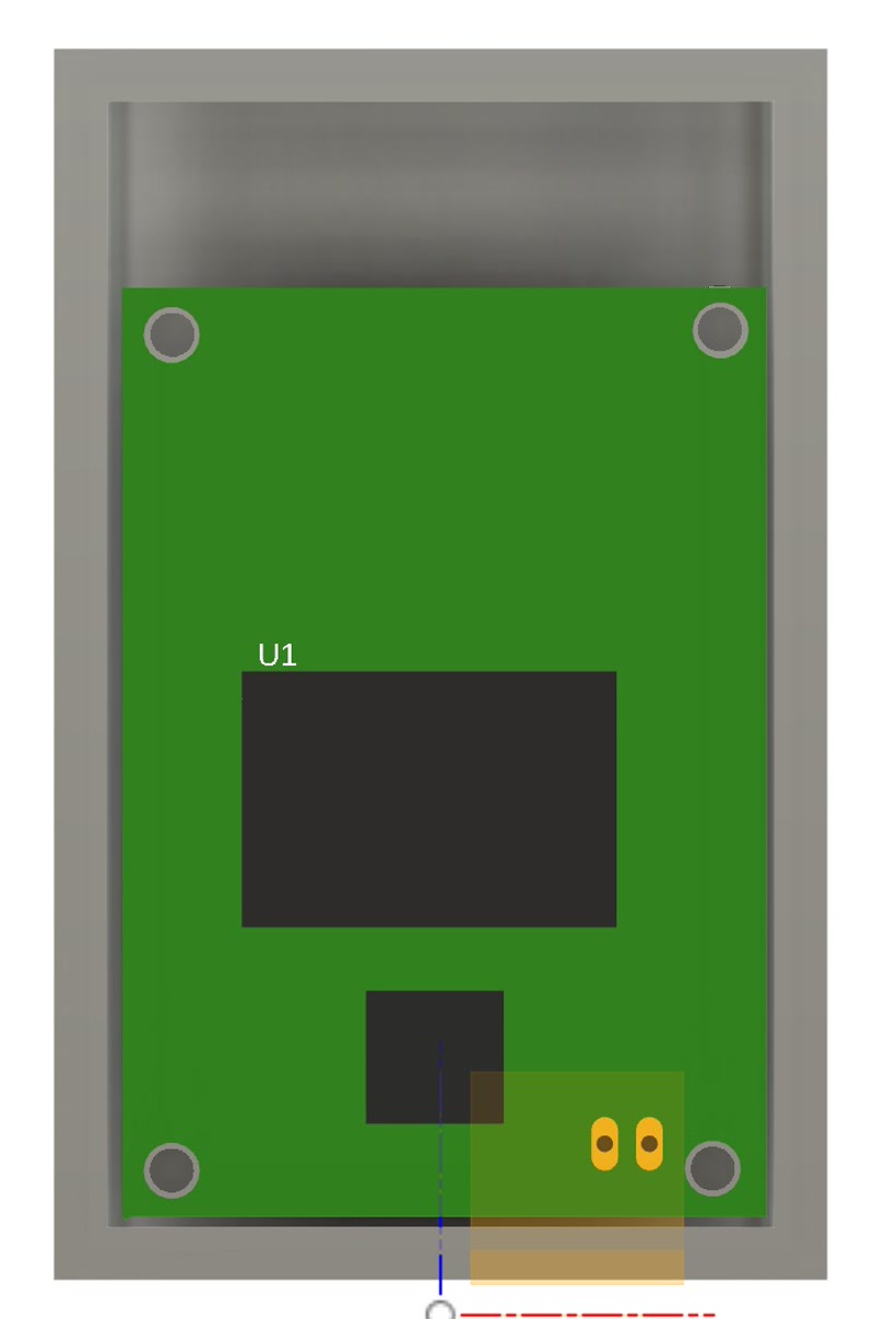
3. Integration of PCB and Internal frame
- Import the 3D model of the PCB into the Fusion 360 enclosure design and align it for a perfect fit to the internal frame.
- Adjusted mounting holes and support structures based on the PCB dimensions and connector positions.

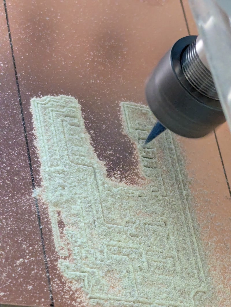
4. PCB Fabrication and Assembly
Based on the PCB data designed in Fusion 360, I physically fabricated the board using a CNC milling machine.
PCB Milling
- Equipment used: CNC router (e.g., Genmitsu PROVerXL 4030)
- Bits used: 0.1mm V-bit (for traces), 0.7mm end mill (for holes and outline)
- Fabrication steps:
- Milled copper traces using
traces.png - Drilled component holes using
millholes.png - Cut the PCB outline using
outline.png
- Milled copper traces using
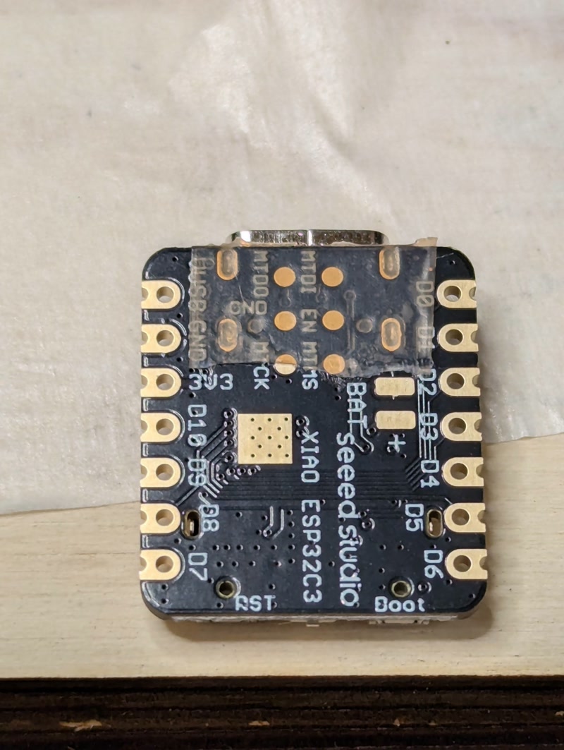
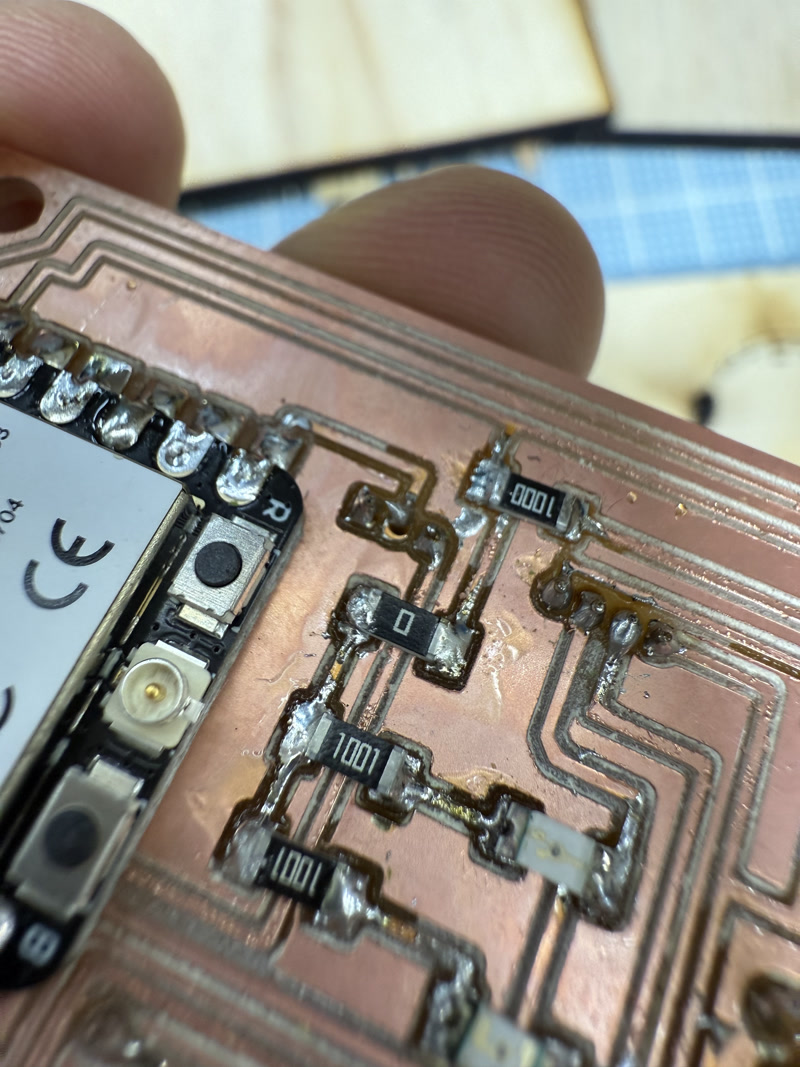
Mounted components:
- ESP32-C3 microcontroller
- 24GHz radar sensor (NJR4265RJ1C1)
- Resistors and capacitors (SMD and through-hole)
- Transistors
- Pin headers (for motor control)
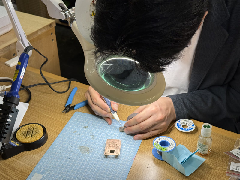
Soldering method:
Through-hole components were soldered manually
SMD components were soldered using tweezers and a temperature-controlled soldering iron
Insulation tape was applied to the bottom of the ESP32-C3 module before mounting to prevent the underside pads from contacting other conductive surfaces
Inspection:
- Performed continuity checks and confirmed power voltage
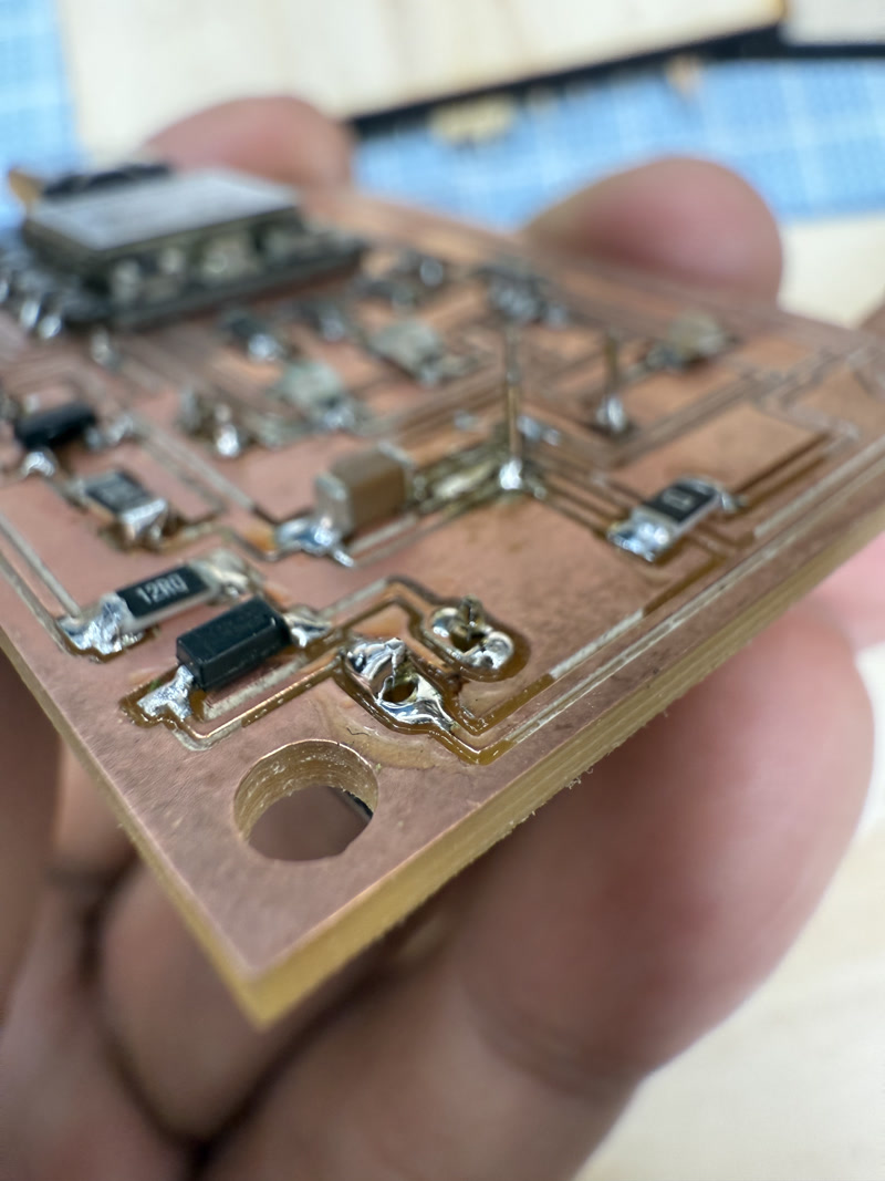
- Performed continuity checks and confirmed power voltage
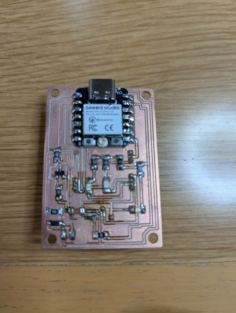
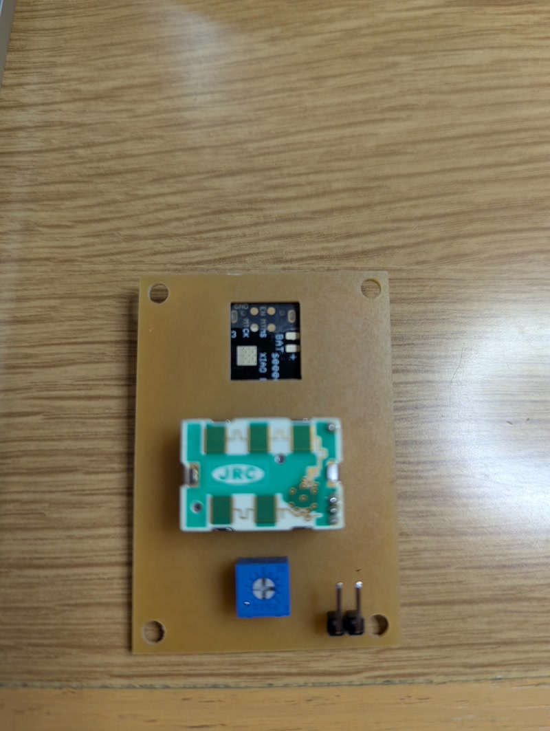
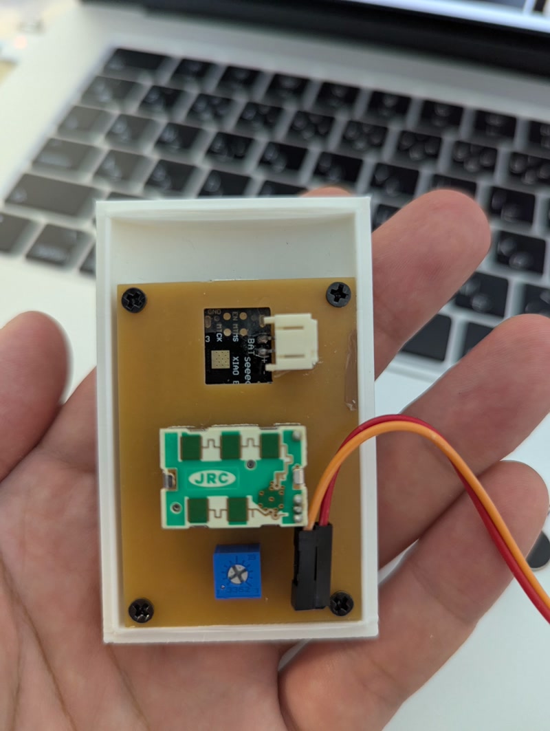
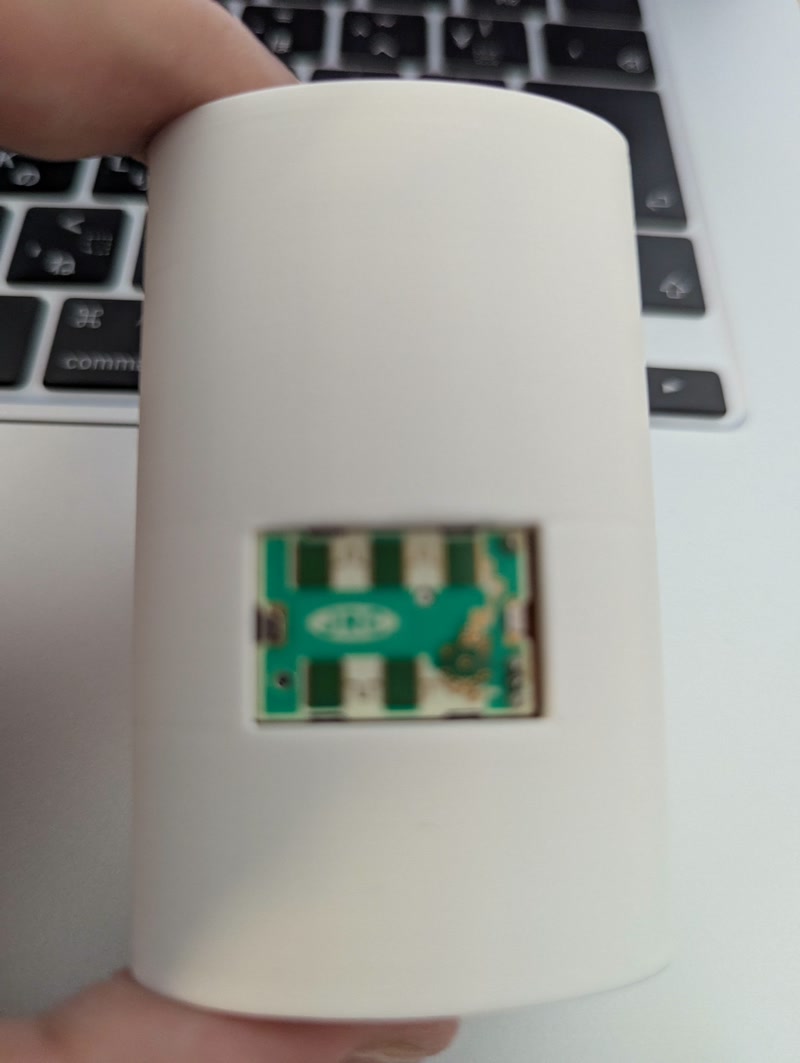
Final Assembly Photos
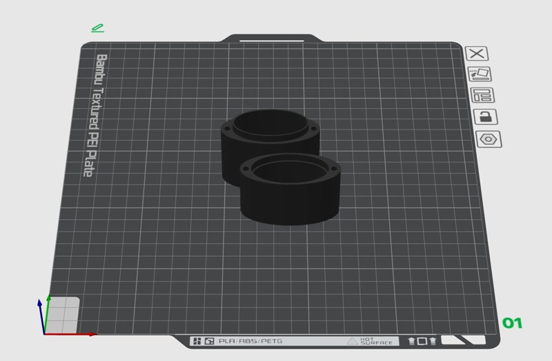
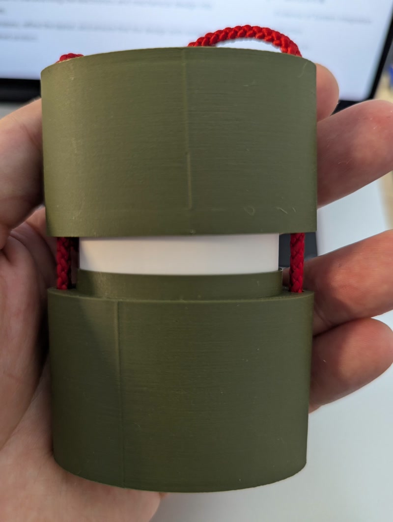
5. 3D Printing of Enclosure and Internal Frame & PCB Integration
After completing the PCB, I printed the designed enclosure and internal frame using a 3D printer, and integrated the PCB.
3D Printing
- Printer used: Bambu Lab P1S
- Filament: PLA (white/green), nozzle diameter: 0.4mm
- Print settings:
- Layer height: 0.2mm
- Infill: 15%
- Supports: auto-generated where needed
Integration Process
- Secured the PCB to the internal frame using screws and confirmed the positions of pin headers and sensors
- Inserted the frame into the enclosure and checked for fit and clearance
- Finalized alignment of external connectors and power input before closing the enclosure
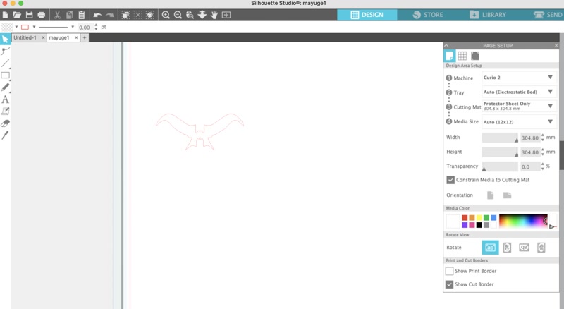
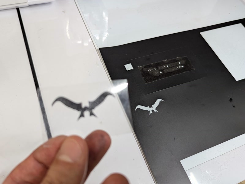
6. Sticker Creation and Decoration
To add character to the enclosure's appearance, I used the Silhouette Curio 2 to create and apply a sticker of Golgo 13's iconic eyebrows.
Sticker Creation Steps
Design preparation: Prepare an image of Golgo 13’s eyebrows
Editing in Silhouette Studio:
- Launch Silhouette Studio and import the image
- Use the tracing tool to convert the image into a path ([Trace Area] → [High Threshold Trace])
- Remove unwanted borders and noise, keeping only the eyebrow path
- Adjust the size and orientation as needed
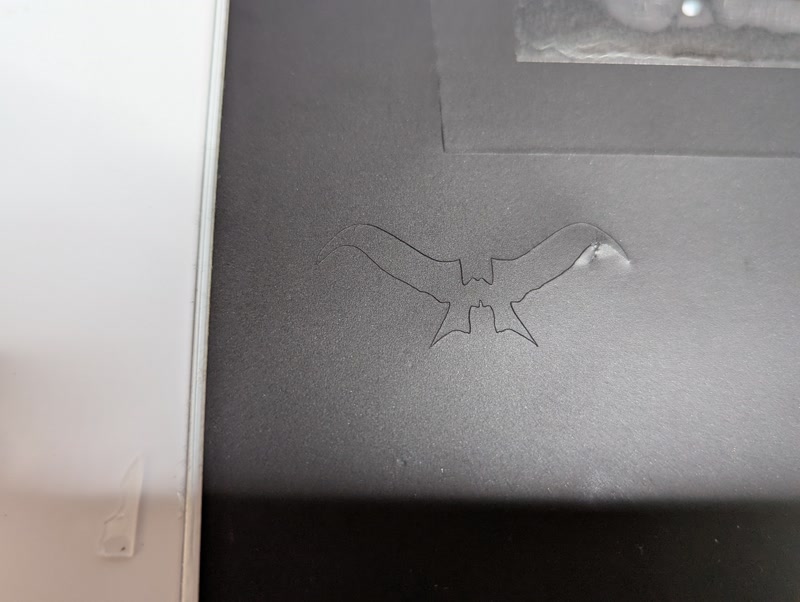
Cutting Setup:
- Equipment: Silhouette Curio 2
- Material: Black vinyl sheet
- Settings: Adjust cutting pressure, blade depth, and speed based on test cuts
Cutting Execution: Accurately cut the eyebrows from the vinyl and weed out unnecessary areas
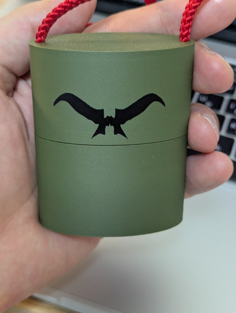
Transfer and Application:
- Use transfer tape to position the sticker carefully on the front of the enclosure
- Remove air bubbles, press firmly, and peel off the transfer tape
Result
- Adding the sticker emphasized the unique identity of the Golgo 13 Machine
- It enhanced the visual impact and made it a standout feature for presentations and exhibitions
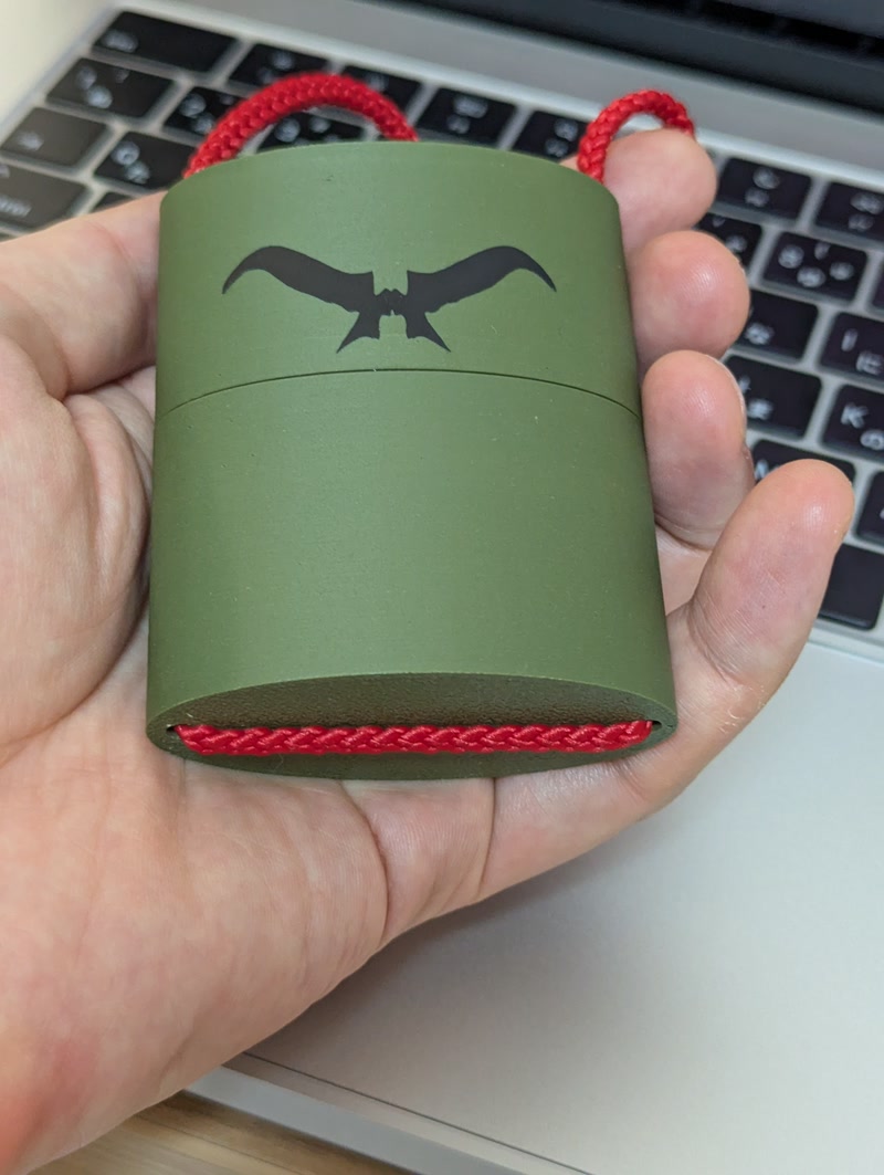
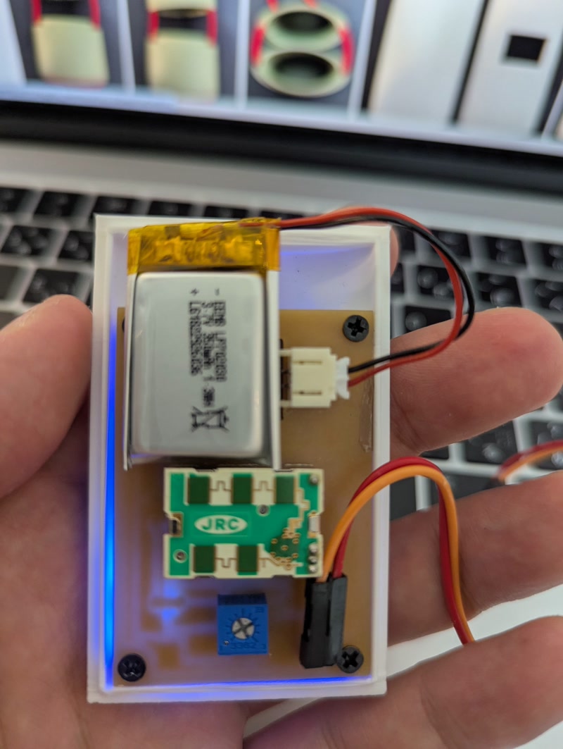
Evidence of System Integration
- The PCB is properly positioned and securely mounted inside the custom-designed enclosure.
3D file Download
PCB file Download
Sticker file Download
Reflection
This integration step was crucial in transforming the electronics and mechanical design into a cohesive, functional system.
I was able to validate dimensions, refine the layout, and ensure that the design both looked and functioned like a finished product.