My Final Project
Slide
Video
Background of the idea
Recently in Japan, random stabbing incidents have been increasing. Innocent people are suddenly attacked, and it's becoming a serious concern. When I imagine myself in their place, I feel uneasy—because these attacks are hard to predict or prevent. Humans can only see about 200 degrees in front of them, leaving a blind spot behind.
While looking for a solution, I found inspiration in the manga Golgo 13. This manga holds a Guinness World Record with 201 volumes—the most for a single series.
The main character, Golgo 13, is a top-level sniper. He’s extremely skilled, but also very cautious—he never lets anyone stand behind him. That detail gave me an idea.
If I could detect when someone is behind me—like Golgo 13—I might be able to prevent such attacks.
Never stand behind me.
Golgo 13 Machine
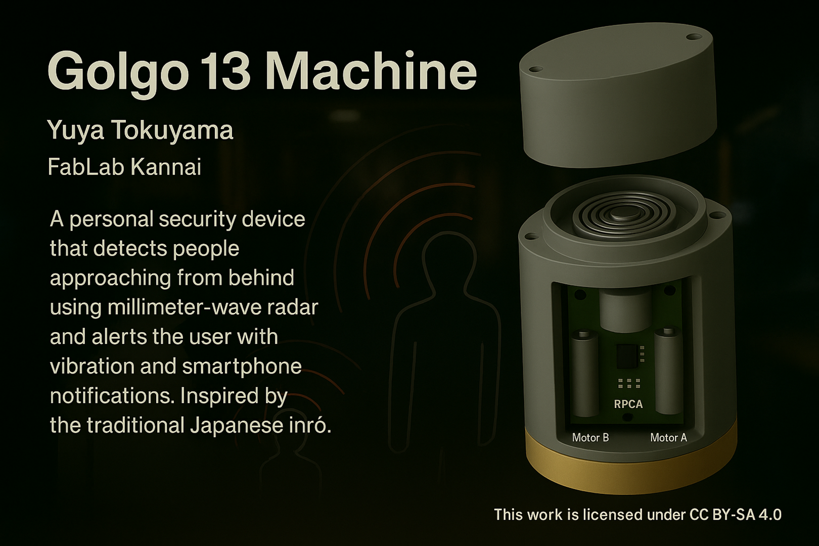
The name of my final project is the Golgo 13 Machine. It is a machine that monitors the area behind it with a millimeter wave radar sensor and alerts you when someone approaches.
Final Project Sketch1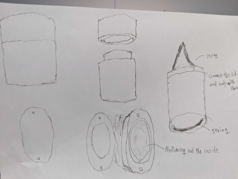
Final Project Sketch2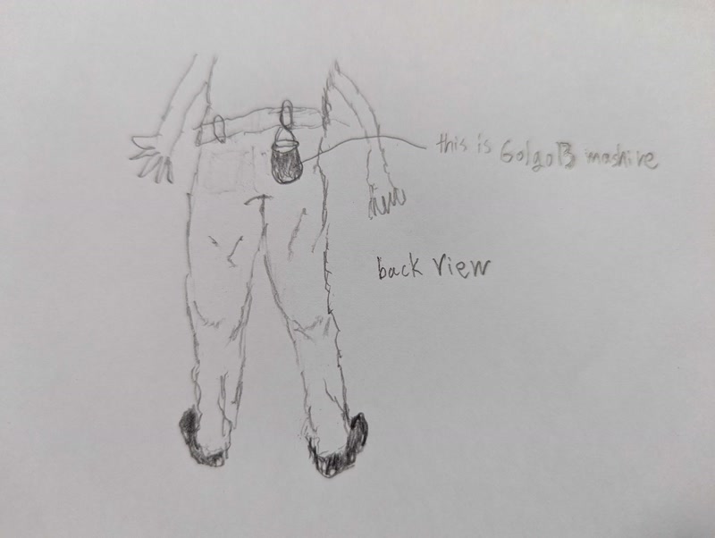
3D model
3D model created with Fusion.
Animation of 3D models
Animation of 3D models created in Fusion.
Requirement Definition
Purpose
To detect a person approaching from behind using a millimeter-wave radar sensor, and to alert the user via vibration and smartphone notification.
Functional Requirements
1. Millimeter-Wave Detection
- The system shall detect objects or people approaching from behind using a millimeter-wave radar sensor.
- Detection range should cover at least 1–2 meters behind the user.
2. Microcontroller Control (XIAO RP2040)
- The microcontroller shall receive and process distance data from the radar sensor.
- It shall determine if the threshold distance is breached.
3. Vibration Alert
- If someone is detected within the danger zone, the device shall activate a vibration motor.
- Vibration intensity may be fixed or adjustable.
4. Smartphone Notification
- The system shall send a wireless alert to the user’s smartphone when detection is triggered.
- BLE (Bluetooth Low Energy) is preferred for real-time communication.
- The notification should include a simple "Alert: Person approaching from behind" message.
5. Optional Features (Future Enhancements)
- Adjustable sensitivity or detection range via smartphone app
- Sound alert in addition to vibration
Hardware Summary
- XIAO ESP32C3
- Millimeter-wave radar sensor
- Vibration motor
- BLE module (or use built-in if available)
- Battery pack
System diagram
The following image shows an overview of the system.

Sequence diagram
The following images visually represent the flow of system processing.

Development Task List
1. Requirement Definition and System Design
- Clarify the purpose and functional requirements for detecting a person approaching from behind
- Create a system block diagram and a sequence diagram
2. Hardware Selection and Preparation
- Select and prepare the XIAO ESP32C3 microcontroller board
- Select and connect a millimeter-wave radar sensor
- Select and connect a vibration motor
- Select and connect a BLE module (including the use of built-in functions if available)
- Select a battery pack and design the power supply system
3. Software Development
- Acquire and analyze data from the millimeter-wave radar sensor
- Control the vibration motor when a threshold is exceeded
- Implement smartphone notification via BLE communication
- Integrate and validate the full system operation
4. Case Design and Fabrication
- Design the enclosure using 3D modeling software (e.g., Fusion 360)
- Fabricate the enclosure using a 3D printer or CNC router
- Design the layout and mounting method for internal components
5. System Integration and Testing
- Integrate hardware and software
- Verify the operation of each component and perform debugging
- Test and adjust the system in real usage conditions
6. Documentation and Submission Preparation
- Document the project overview, design drawings, circuit diagrams, and source code
- Take and edit photos and videos of the project
- Create a final presentation slide deck and a 1-minute demo video
- Organize and prepare all required files and materials for submission
Development Schedule
Schedule (May 10 – June 6)
| Period | Task Category | Details |
|---|---|---|
| May 10 (Fri) – May 16 (Thu) | ② Hardware Preparation | - Select and test XIAO RP2040, mmWave radar, motor, and BLE module - Create circuit diagrams and test on a breadboard - Complete parts procurement |
| May 17 (Fri) – May 23 (Thu) | ③ Software Development | - Acquire and analyze sensor data - Develop vibration motor control logic - Implement BLE communication for smartphone notifications |
| May 24 (Fri) – May 29 (Wed) | ④ Case Design & Fabrication | - Design enclosure using 3D CAD (e.g., Fusion 360) - Fabricate using 3D printer or CNC router - Plan and test internal component layout |
| May 30 (Thu) – June 2 (Sun) | ⑤ System Integration & Testing | - Integrate hardware and software - Perform functional testing and debugging - Evaluate in real-world scenarios |
| June 3 (Mon) – June 5 (Wed) | ⑥ Documentation & Submission Prep | - Capture and edit project photos/videos - Prepare final presentation slides and 1-minute demo video - Update website and organize submission materials |
| June 6 (Thu) | Submission Day | - Final review and upload |
System integration
System integration was carried out in Week 15.
For details, please refer to the Week 15 page.
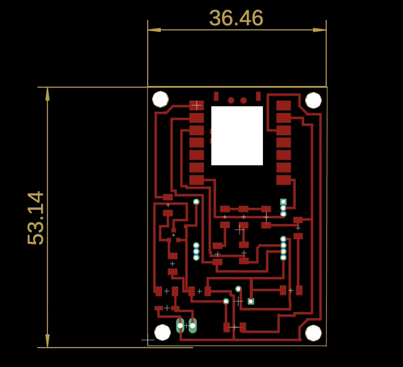
1. PCB Design
To enable system integration, I designed a custom PCB using Fusion 360 tailored to the final project.
The board includes headers for connecting sensors, power input, and communication pins.
Design Process
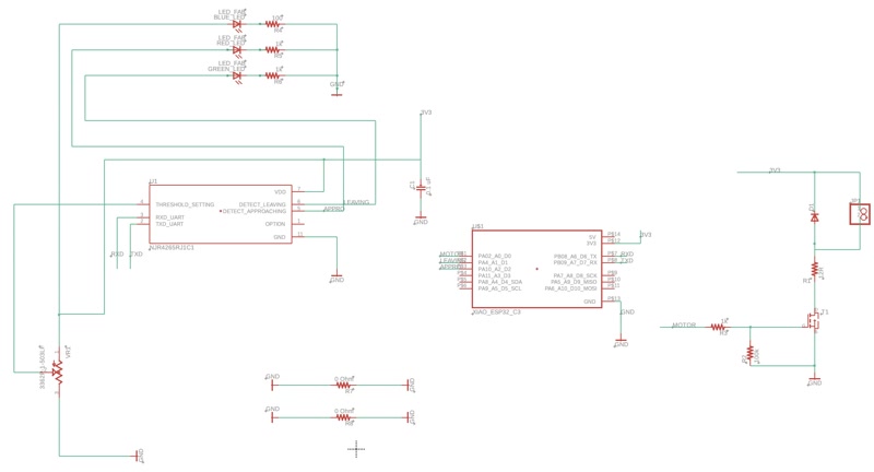
- Circuit Schematic Design
I first created a circuit schematic in Fusion 360 and placed key components such as:
- XIAO ESP32-C3 microcontroller
- 24GHz motion detection / Doppler radar sensor module
- Transistors
- Resistors and capacitors
- Pin headers for external motor connection
- PCB Layout
After completing the schematic, I moved on to the PCB layout.
- I routed the traces carefully to avoid interference.
- I added mounting holes to match the design of the enclosure.
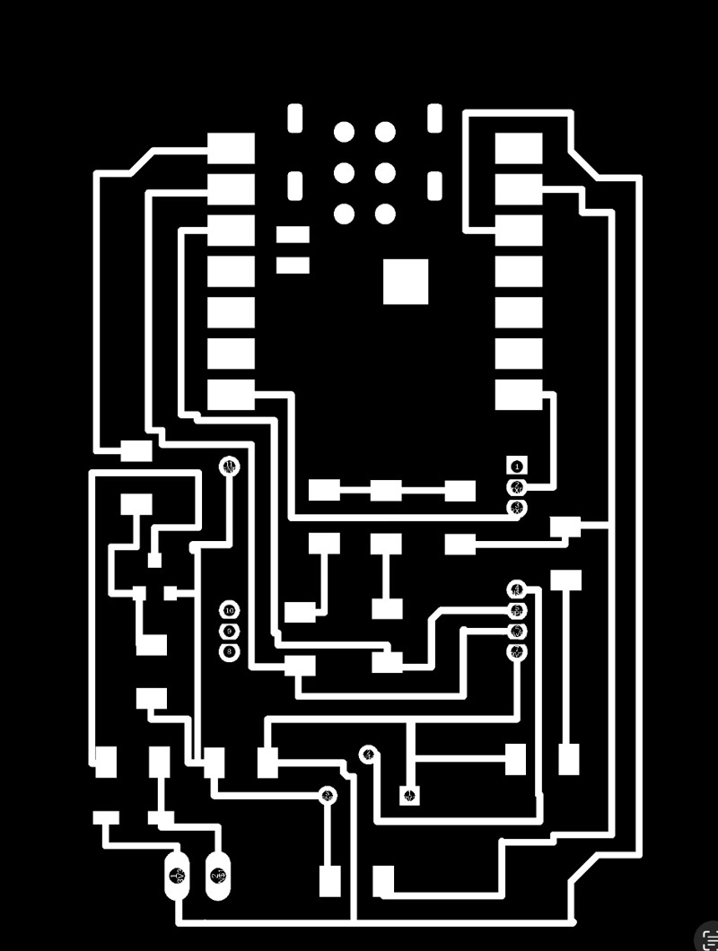
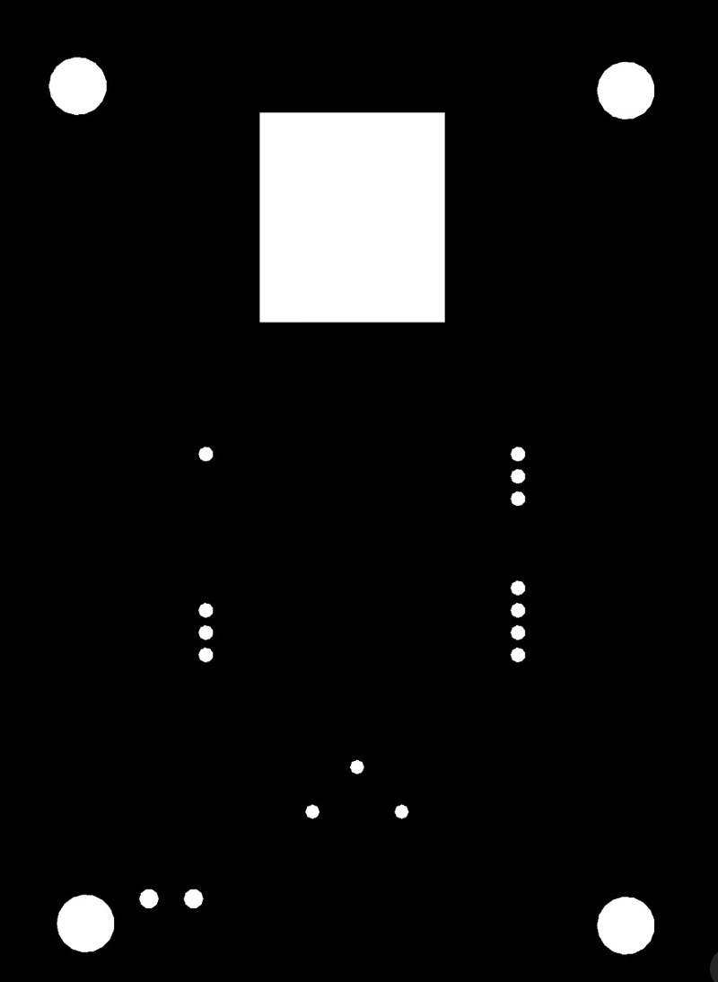
- Exporting PNG Files
To fabricate the PCB using a CNC milling machine, I exported the following files:
traces.png: for milling copper tracesmillholes.png: for drilling component holesoutline.png: for cutting the board outline

TIP
- All traces were verified using Design Rule Check (DRC).
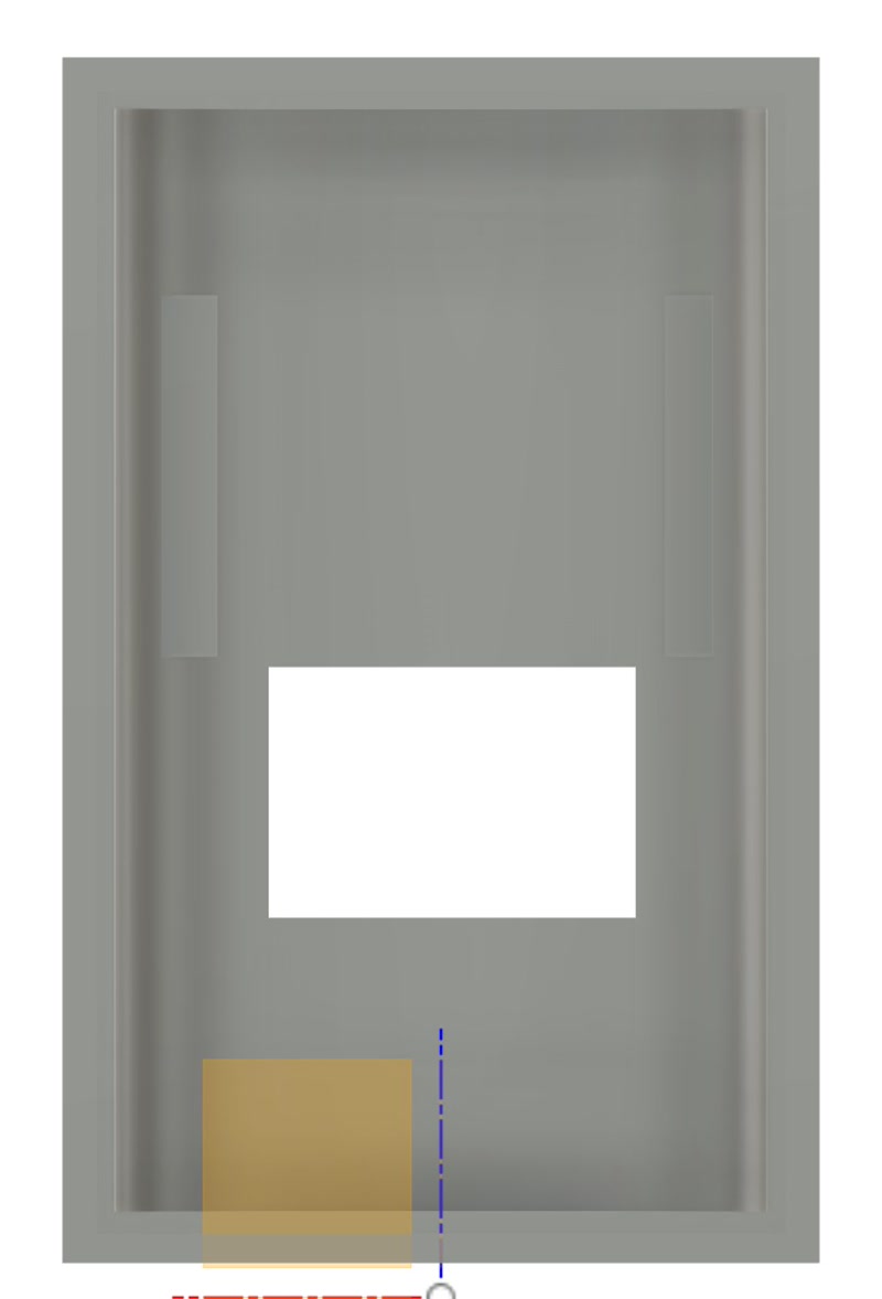
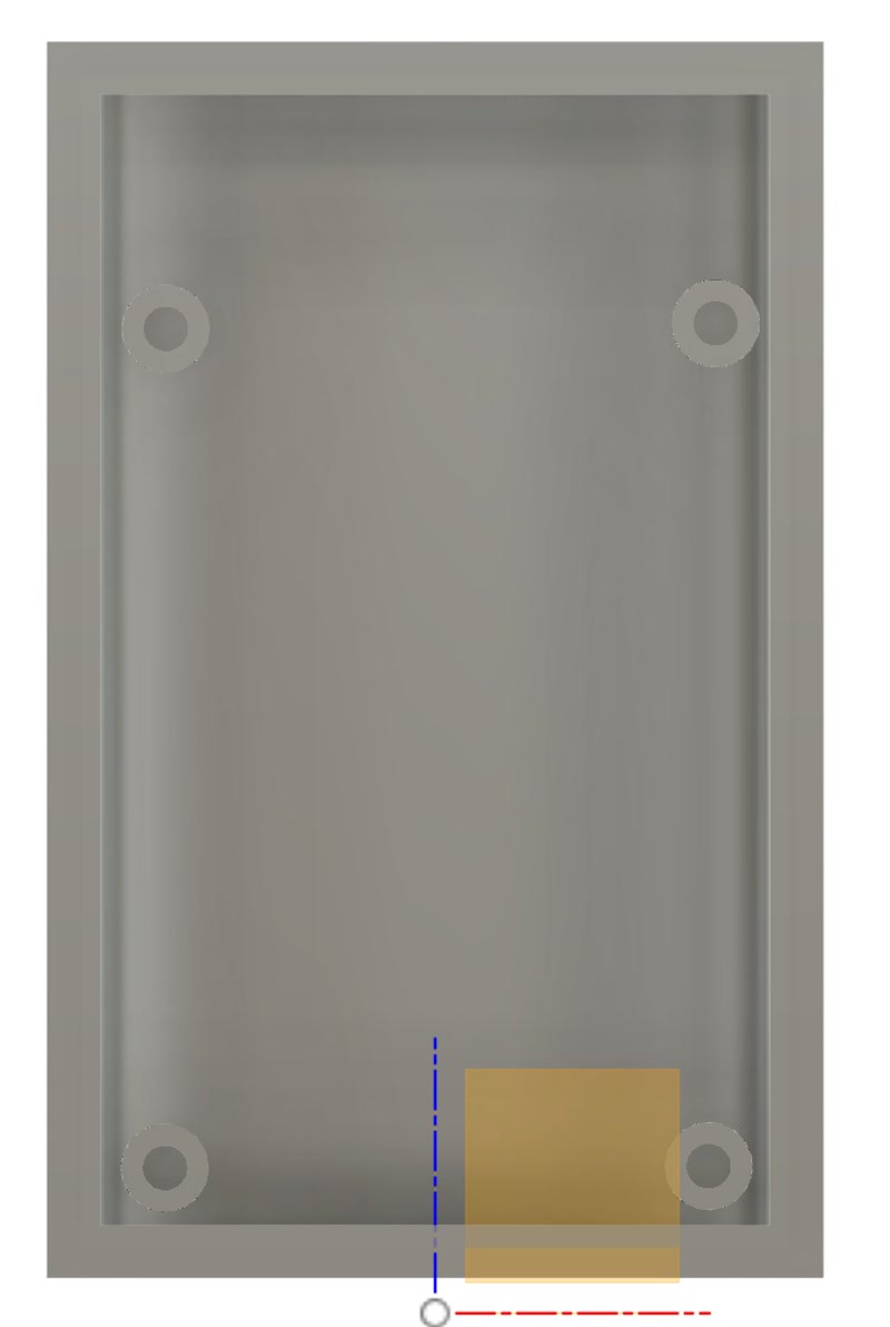
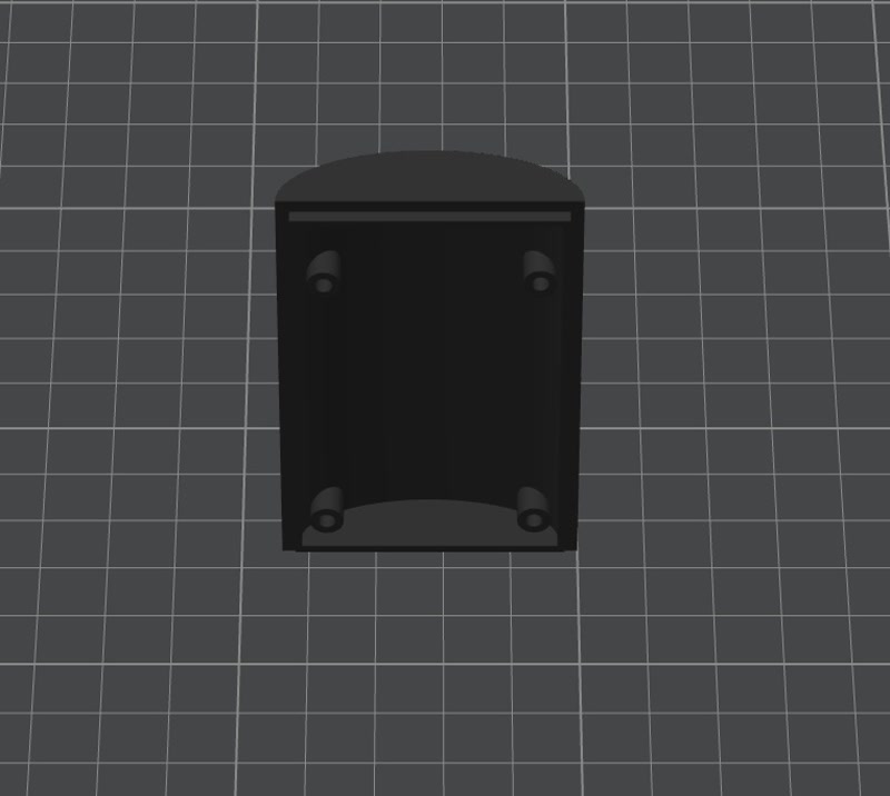
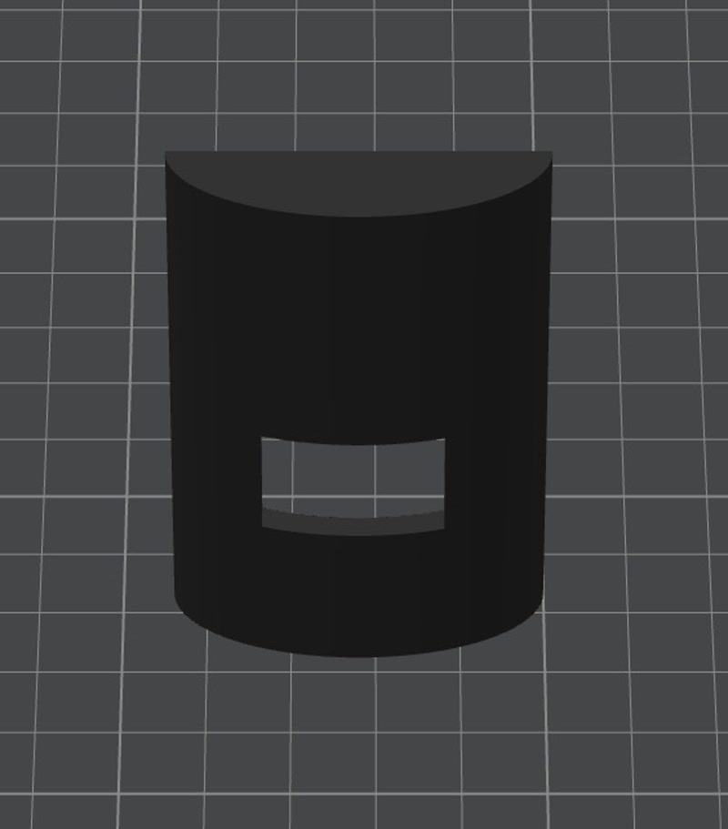
2. Enclosure Design
I modified the 3D model created in week02 to accommodate the PCB.
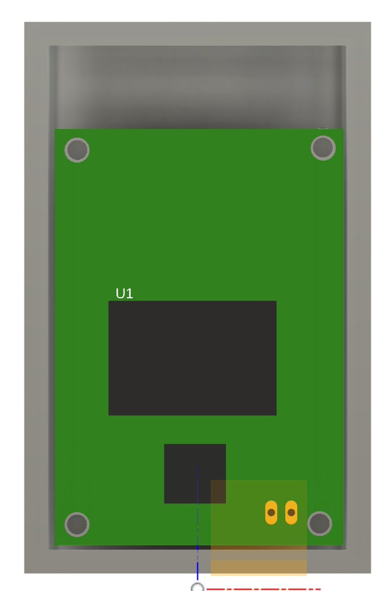
3. Integration of PCB and Internal frame
- Import the 3D model of the PCB into the Fusion 360 enclosure design and align it for a perfect fit to the internal frame.
- Adjusted mounting holes and support structures based on the PCB dimensions and connector positions.

3D Assembly Animation in Fusion 360
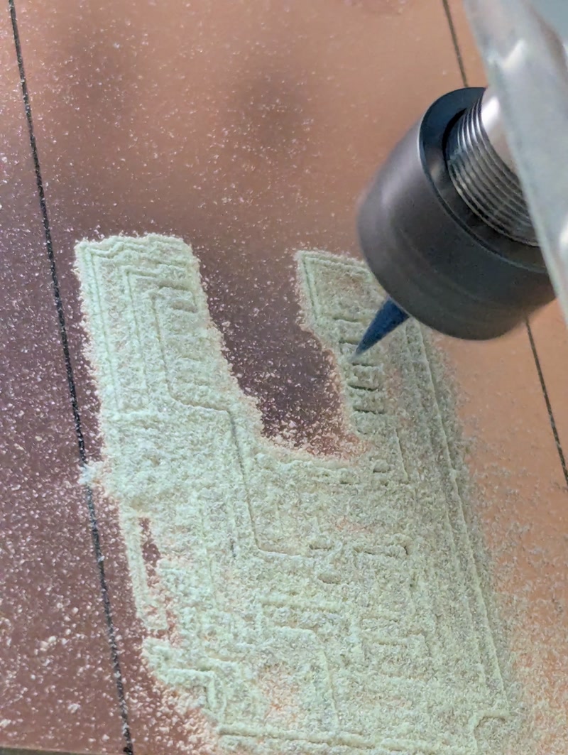
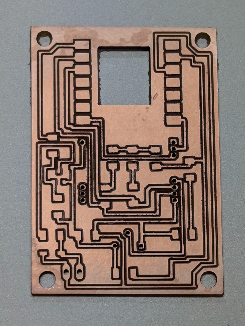
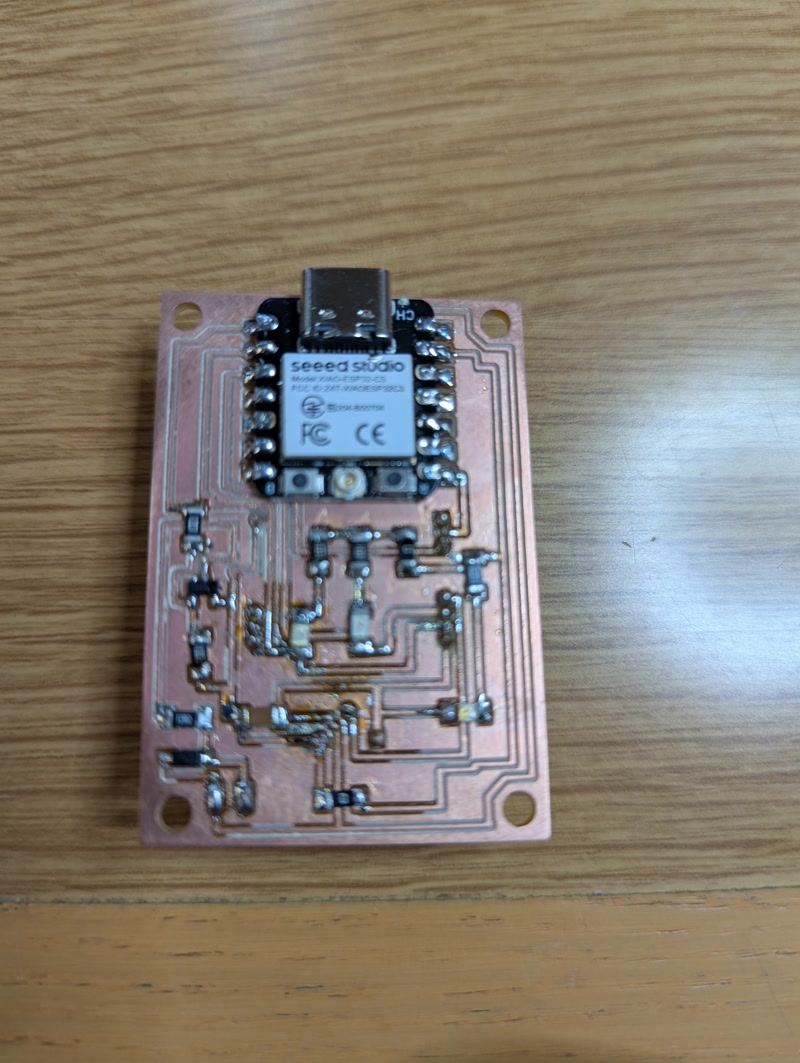
4. PCB Fabrication and Assembly
Based on the PCB data designed in Fusion 360, I physically fabricated the board using a CNC milling machine.
PCB Milling
- Equipment used: CNC router (e.g., Genmitsu PROVerXL 4030)
- Bits used: 0.1mm V-bit (for traces), 0.7mm end mill (for holes and outline)
- Fabrication steps:
- Milled copper traces using
traces.png - Drilled component holes using
millholes.png - Cut the PCB outline using
outline.png
- Milled copper traces using
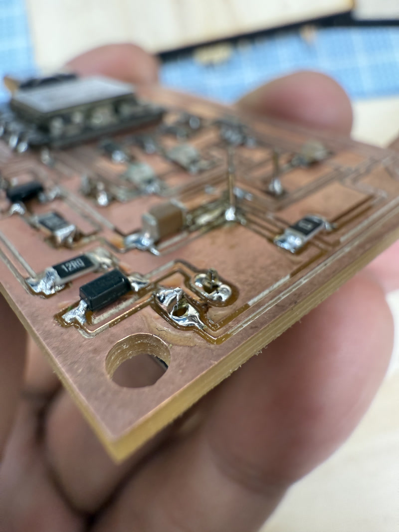
Mounted components:
- XIAO ESP32-C3 microcontroller
- 24GHz radar sensor (NJR4265RJ1C1)
- Resistors and capacitors (SMD and through-hole)
- Transistors
- Pin headers (for motor control)
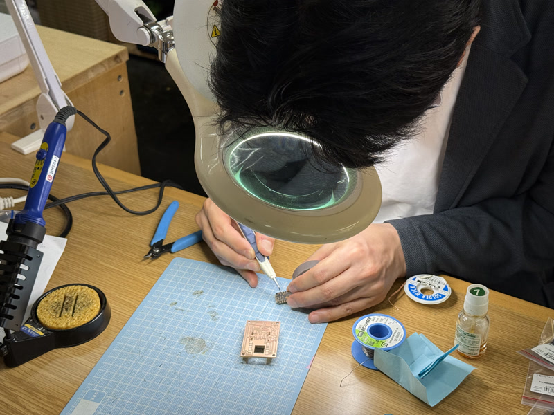
Soldering method:
Through-hole components were soldered manually
SMD components were soldered using tweezers and a temperature-controlled soldering iron
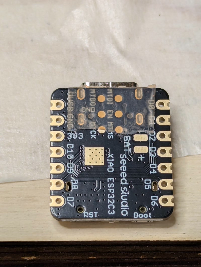
Insulation tape was applied to the bottom of the XIAO ESP32-C3 module before mounting to prevent the underside pads from contacting other conductive surfaces
Inspection:
- Performed continuity checks and confirmed power voltage
- Performed continuity checks and confirmed power voltage
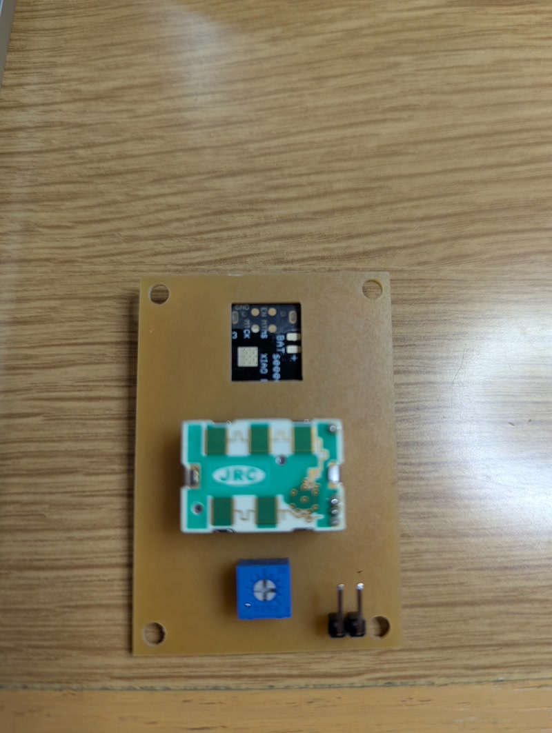
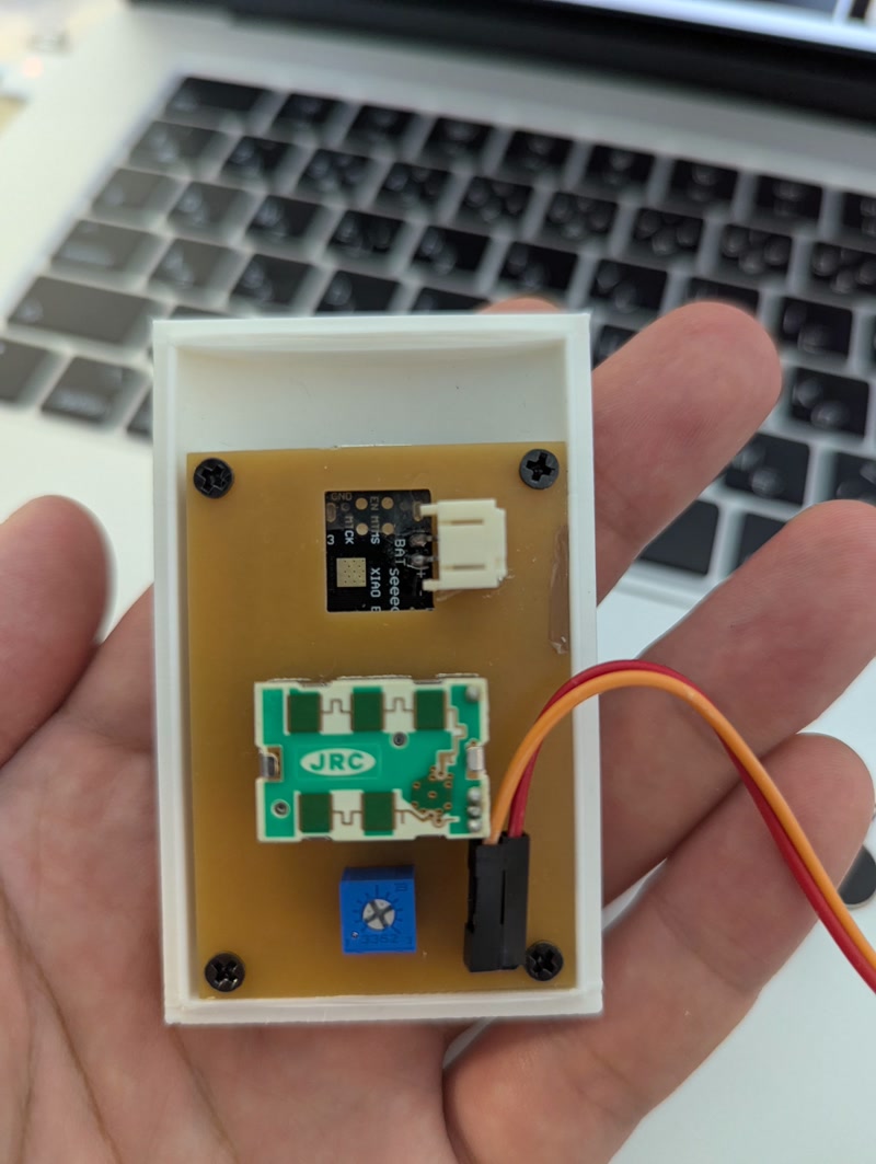
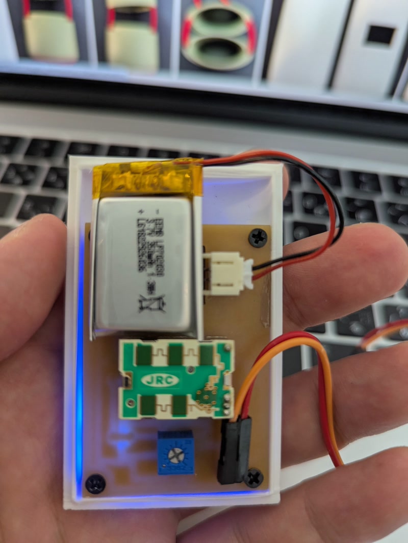
Final Assembly Photos
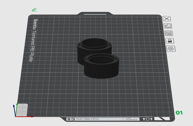
5. 3D Printing of Enclosure and Internal Frame & PCB Integration
After completing the PCB, I printed the designed enclosure and internal frame using a 3D printer, and integrated the PCB.
3D Printing
- Printer used: Bambu Lab P1S
- Filament: PLA (white/green), nozzle diameter: 0.4mm
- Print settings:
- Layer height: 0.2mm
- Infill: 15%
- Supports: auto-generated where needed
Integration Process
- Secured the PCB to the internal frame using screws and confirmed the positions of pin headers and sensors
- Inserted the frame into the enclosure and checked for fit and clearance
- Finalized alignment of external connectors and power input before closing the enclosure
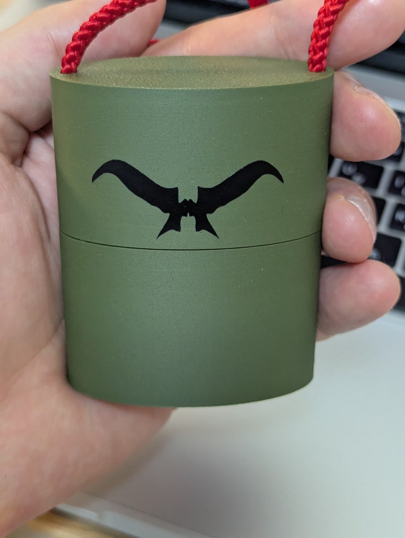
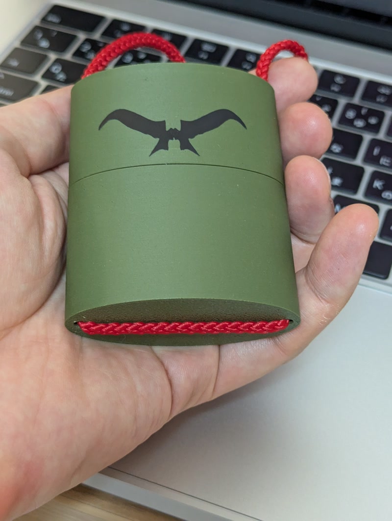
6. Sticker Creation and Decoration
To add character to the enclosure's appearance, I used the Silhouette Curio 2 to create and apply a sticker of Golgo 13's iconic eyebrows.
Sticker Creation Steps
Design preparation: Prepare an image of Golgo 13’s eyebrows
Editing in Silhouette Studio:
- Launch Silhouette Studio and import the image
- Use the tracing tool to convert the image into a path ([Trace Area] → [High Threshold Trace])
- Remove unwanted borders and noise, keeping only the eyebrow path
- Adjust the size and orientation as needed
Cutting Setup:
- Equipment: Silhouette Curio 2
- Material: Black vinyl sheet
- Settings: Adjust cutting pressure, blade depth, and speed based on test cuts
Cutting Execution: Accurately cut the eyebrows from the vinyl and weed out unnecessary areas
Transfer and Application:
- Use transfer tape to position the sticker carefully on the front of the enclosure
- Remove air bubbles, press firmly, and peel off the transfer tape
Result
- Adding the sticker emphasized the unique identity of the Golgo 13 Machine
- It enhanced the visual impact and made it a standout feature for presentations and exhibitions
Evidence of System Integration
- The PCB is properly positioned and securely mounted inside the custom-designed enclosure.
3D file Download
PCB file Download
Sticker file Download
Reflection
This integration step was crucial in transforming the electronics and mechanical design into a cohesive, functional system.
I was able to validate dimensions, refine the layout, and ensure that the design both looked and functioned like a finished product.
Bill of Materials (BOM)
| Type | Item | Quantity | Note | Source | Cost |
|---|---|---|---|---|---|
| MCU | U$1 (XIAO ESP32C3) | 1 | Development board (Seeed Studio) | AKIZUKI DENSHI | ¥1,080 |
| Sensor | U1 (NJR4265RJ1C1) | 1 | Doppler sensor module (10m CW mode) | AKIZUKI DENSHI | ¥2,300 |
| Motor | Motor | 1 | Mini vibration motor 2.0mm | AKIZUKI DENSHI | ¥180 |
| Trimmer | VR1 (3362P-1-503LF) | 1 | 50kΩ Single-turn Trimmer (Bourns) | AKIZUKI DENSHI | ¥50 |
| LED | Blue LED | 1 | Blue LED (1206 size) | AKIZUKI DENSHI | ¥10 |
| LED | GREEN_LED | 1 | Green LED (1206 size) | AKIZUKI DENSHI | ¥13 |
| LED | RED_LED | 1 | Red LED (1206 size) | AKIZUKI DENSHI | ¥10 |
| Capacitor | C1 (1uF) | 1 | Ceramic capacitor 1206 | AKIZUKI DENSHI | ¥70 |
| Diode | D1 | 1 | General-purpose diode (SOD-123 package) | AKIZUKI DENSHI | ¥8 |
| Header | JP1 | 1 | 2-pin pin header (2.54mm pitch) | AKIZUKI DENSHI | ¥35 |
| Resistor | R1 (12Ω) | 1 | Chip resistor 1206 | RS | ¥15 |
| Resistor | R2 (100kΩ) | 1 | Chip resistor 1206 | RS | ¥49 |
| Resistor | R3,R5,R6 (1kΩ) | 3 | Chip resistor 1206 | RS | ¥16 |
| Resistor | R4 (100Ω) | 1 | Chip resistor 1206 | RS | ¥99 |
| Resistor | R7,R8 (0Ω) | 2 | Jumper resistor | RS | ¥5 |
| Transistor | T1 | 1 | SOT-23 MOSFET | AKIZUKI DENSHI | ¥33 |
| Total | ¥3,973 |
Doppler sensor testing
You can see that the red LED lights up only when the sensor detects someone approaching, and the green LED lights up when the person moves away. The Doppler sensor testing is working as expected, so there are no issues!
Programming
Although I encountered several issues, I was finally able to make the mini vibration motor vibrate upon approach detection.
Issue 1
Initially, I connected the motor output to GPIO2 (D0) on the XIAO ESP32-C3, but it didn’t work as expected when trying to control it through the program.
The root cause turned out to be the use of GPIO2 (D0), which is one of the boot strapping pins on the XIAO ESP32-C3.
Boot strapping pins are critical because the XIAO ESP32-C3 reads the logic levels of specific GPIOs at reset to determine the boot mode.
If GPIO2 is LOW at boot, the device may enter UART download mode instead of executing the user program.
Even if the pin is HIGH at boot and normal startup occurs, GPIO2 is still in an input (HIGH) state when setup() begins, so it cannot be used as an output pin to drive a MOSFET. As a result, the motor cannot be turned on.
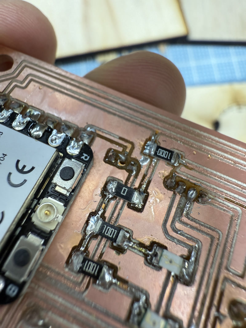
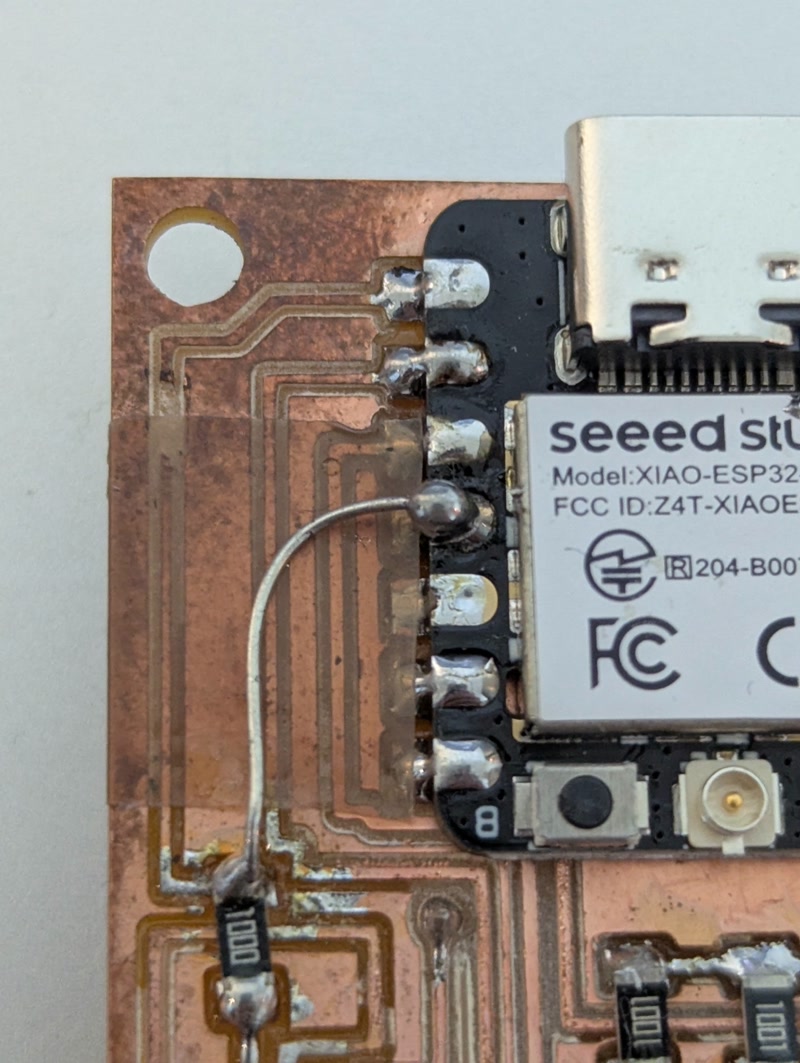
As a result, I abandoned using GPIO2 (D0) and decided to switch to GPIO5 (D3) instead.
Since I didn’t have enough time to redesign and re-mill the PCB, I cut the trace connected to GPIO2 and manually rewired the circuit by connecting GPIO5 directly using tinned copper wire.
Arduino Code 1
With the following code, I was finally able to make the mini vibration motor vibrate when approach detection is triggered.
#define  VIBRATION_PIN 5    // D3 = GPIO5
#define  APPROACHING_PIN 3  // D2 → GPIO3(Approach Detection)

unsigned long vibrationStartTime = 0;
bool isVibrating = false;

void setup() {

  pinMode(VIBRATION_PIN, OUTPUT);
  digitalWrite(VIBRATION_PIN, LOW);
  pinMode(APPROACHING_PIN, INPUT);

  Serial.begin(115200);  // For USB serial monitor
}

void loop() {
  int isApproaching = digitalRead(APPROACHING_PIN);

  Serial.print(isApproaching);

  unsigned long currentTime = millis();

  // The motor starts vibrating or extends its vibration time when approach detection is triggered
  if (isApproaching == 1) {
    if (!isVibrating) {
      Serial.println("Motor High.");
      digitalWrite(VIBRATION_PIN, HIGH);  // Vibration ON
      isVibrating = true;
    }
    vibrationStartTime = currentTime;  // reset every time
    Serial.println("!!! WARNING: Approaching detected. Vibrating...");
  }

  // Vibration stops after a certain period of time
  if (isVibrating && (currentTime - vibrationStartTime >= 5000)) {
    digitalWrite(VIBRATION_PIN, LOW);  // Vibration OFF
    Serial.println("Motor Low.");
    Serial.println("Stop vibrating.");
    isVibrating = false;
  }

  delay(100);  // Read Interval
}
Issue 2
Although the mini vibration motor now vibrates upon approach detection, there were times when the red LED used for approach detection (which is lit directly by the Doppler sensor) blinked, but the sensor values received by the XIAO ESP32-C3 did not match this activity.
This discrepancy made me suspect that the data retrieval method might be incorrect.
After reviewing the sensor’s manual, I found that there is a method for retrieving real-time sensor values via UART communication.
I decided to switch the implementation to use UART for real-time data acquisition.
I referred to this published code as a reference for setting up UART-based real-time communication.
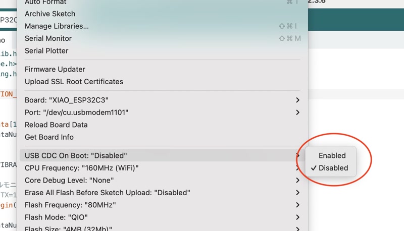
The UART output destination can be configured using the "USB CDC On Boot" option.
If this is set to "Enable", the UART data will be sent over the USB connection.
In this case, I set it to "Disable" so that the data would flow through the TXD/RXD pins (D6/D7) instead.
Arduino Code 2
Using the UART-based real-time data acquisition code shown below, I was successfully able to synchronize the sensor's output values with the blinking of the red LED used for approach detection.
#include <stdlib.h>
#include <ctype.h>
#include <string.h>

#define VIBRATION_PIN 5       // D3 = GPIO5

char ReceiveData[12] ;        // Buffer for receiving communication commands
int  ReceiveDataNum ;         // Communication command string length and receive flag variable

void setup() {
     pinMode(VIBRATION_PIN, OUTPUT);   // Vibration motor pin set to output

     // Serial Monitor Settings
     // (RX=6 TX=7 BaudRate=9600bps Data=8bit Parity=odd Stop=1bit Flow=none)
     Serial.begin(9600,SERIAL_8O1) ;

     ReceiveDataNum = -1 ;
}

void loop() {
  int ans ;

  // Receiving communication commands
  ans = receiveCommand() ;
  if (ans != -1) {
      // Processing of received communication commands
      processCommand(ans) ;
  }
}

// Processes received communication commands.
// num: Character length of received command
void processCommand(int num) {
  switch(ReceiveData[1]) {
    case 'W':// Startup complete
        digitalWrite(VIBRATION_PIN, HIGH) ;
        delay(2000) ;
        digitalWrite(VIBRATION_PIN, LOW) ;
        // Set thresholds (aproaching=10m/leaving=10m)
        setThreshold(999,999);
        delay(2000) ;
        // Set to moving object detection mode
        setDetectionMode();
        delay(2000) ;
        break ;
    case 'C':// Moving object approaching
        digitalWrite(VIBRATION_PIN, HIGH) ;
        break ;
    case 'L':// Moving objects leaving
        break ;
    case 'N':// There's nothing to move
        digitalWrite(VIBRATION_PIN, LOW) ;
        break ;
    case 'E':// error
        break ;
  }
}

void setThreshold(int sp,int sm) {
     char buf[8] ;

     // Send approaching threshold
     sprintf(buf,"@SP%d\r\n",sp) ;
     Serial.print(buf) ;
     // Send leaving threshold
     sprintf(buf,"@SM%d\r\n",sm) ;
     Serial.print(buf) ;
}

void setDetectionMode() {
     // Set to moving object detection mode
     Serial.print("@T\r\n");
}

int receiveCommand() {
     int  ans , ret ;
     char dt ;

     ret = -1 ;
     while(1) {
          // If there is incoming data, process it
          ans = Serial.available() ;
          if (ans > 0) {
               // read out 1 byte
               dt = Serial.read() ;
               // Start of communication command
               if (dt == '@') ReceiveDataNum = 0 ;
               if (ReceiveDataNum >= 0) {
                    // Buffer communication commands
                    ReceiveData[ReceiveDataNum] = dt ;
                    ReceiveDataNum++ ;
                    // End of communication command (CR/LF)
                    if (dt == '\n' && ReceiveData[ReceiveDataNum-2] == '\r') {
                         ret = ReceiveDataNum ;
                         ReceiveDataNum = -1 ;
                         break ;
                    }
               }
          } else break ;
     }
     return ret ;
}
Vibration Motor Test
We uploaded the improved program to the ESP32-C3 and conducted a test to verify whether the vibration motor functions correctly when triggered by the proximity detection signal from the Doppler sensor.
The vibration motor was connected to the XIAO ESP32-C3 mounted on the PCB, and the Doppler sensor (NJR4265) was placed in a setting similar to the actual usage environment.
When the sensor is activated in proximity detection mode and detects human movement, the ESP32-C3 receives the signal via UART communication and sets the designated pin (GPIO5) to HIGH, turning the vibration motor ON.
Test Items
- Does the vibration motor activate upon detecting proximity?
- Is the motor’s operation synchronized with the red LED indicator on the sensor?
- Does the vibration motor automatically stop when no signal is received?
Test Results
All test items were passed successfully.
When the Doppler sensor detected proximity, the vibration motor immediately started operating, and it was confirmed that the motor automatically stopped when the signal ceased.
Additionally, there was no delay between the red LED lighting up on the sensor and the motor vibration, demonstrating highly responsive real-time control.
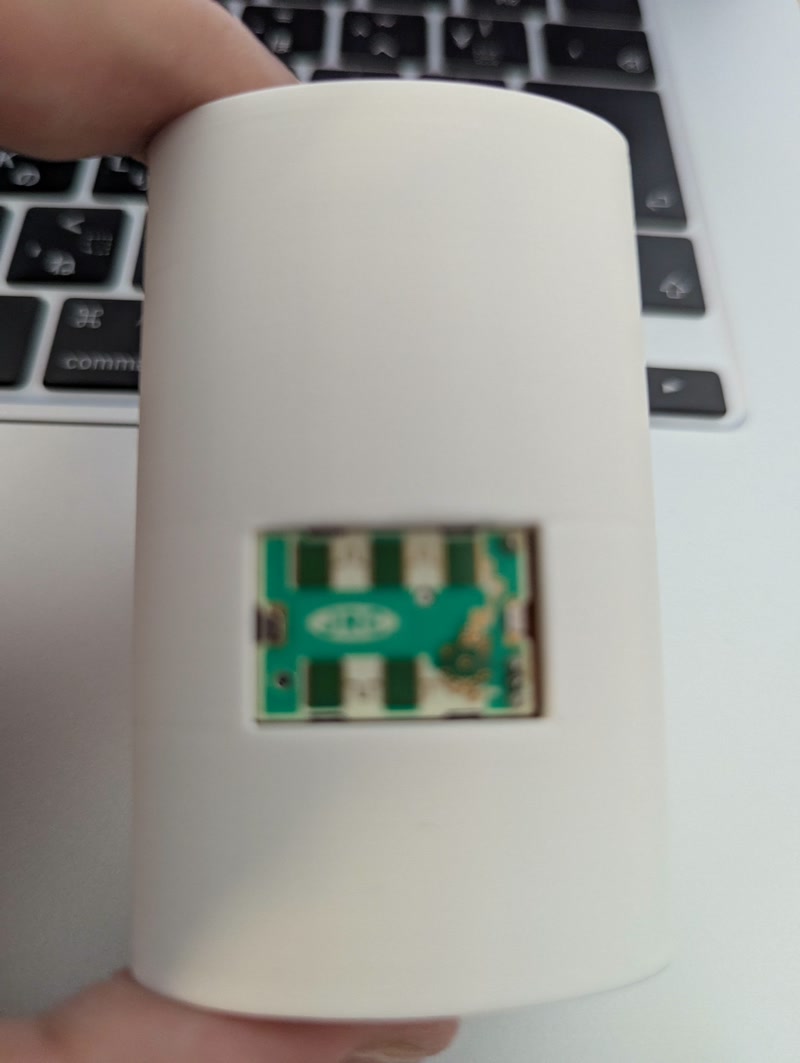
Vibration Test of Final Device
After integrating the vibration motor module into the final enclosure, we conducted a test to verify whether the system functions correctly under actual usage conditions.
The enclosure was fully assembled, including the XIAO ESP32-C3, NJR4265 Doppler sensor, and the vibration motor securely mounted inside. This test simulated real-world use, where the sensor detects movement from behind, and the vibration motor alerts the wearer inside the enclosed form factor.
Test Items (Final Assembly)
- Does the vibration motor operate reliably when triggered inside the enclosed casing?
- Is the vibration intensity clearly perceivable through the casing when the sensor is activated?
- Does the enclosure affect the timing or sensitivity of the sensor's detection?
- Is there any delay between the detection event and motor activation inside the final hardware setup?
- Does the motor stop correctly when no signal is received, even when housed inside the case?
- Does the mechanical mounting of the motor inside the case remain stable during repeated activations?
Test Results
All items were successfully verified.
The vibration motor responded immediately and consistently when proximity was detected by the Doppler sensor, even with all components enclosed. The vibration feedback was strong enough to be felt clearly through the final casing.
Sensor responsiveness and signal timing were not negatively affected by the enclosure. The internal mounting structure held the motor firmly in place without any loosening or shifting.
This confirms that the complete system performs reliably in its intended wearable configuration.
Final Project Dissemination Plan
My final project, "Golgo 13 Machine," is a personal security device that uses a millimeter-wave radar sensor to detect people approaching from behind and alerts the user via vibration and smartphone notifications. The device is uniquely designed in the shape of a traditional Japanese inrō, blending cultural aesthetics with modern technology.
The project will be disseminated and made publicly available through the following methods:
- Circuit diagrams, design files, and code will be published as open-source on GitHub (in preparation)
- Planned exhibition at local FabLab events (to be held at FabLab Kannai after graduation)
- An introduction video with English subtitles will be uploaded to YouTube (currently being edited)
All design files, source code, and documentation for this project will be released under the
Creative Commons Attribution-ShareAlike 4.0 International (CC BY-SA 4.0)
license.
This license allows anyone to freely reuse, modify, and distribute the work, provided that derivative works are also shared under the same license.
Future Possibilities and Pathways for Realization
This project has the potential for the following future applications:
- Elderly care: As an alert system for individuals with visual or auditory impairments, especially useful for detecting approaching individuals.
- Wearable devices for disaster evacuation: The sensor's ability to operate in dark or smoky environments could assist in evacuation scenarios.
- Commercial product development with cultural motifs: Leveraging the unique Japanese aesthetic for niche wearable markets.
To turn these possibilities into reality, I plan to:
- Strengthen integration with a smartphone app utilizing BLE notifications
- Propose a crowdfunding campaign focusing on the fusion of Japanese tradition and security technology
Presentation
Slide
I created the following presentation slides using Canva.
Video
I created the following presentation video using Canva and Veed.io.
Lessons Learned and Reflections
Throughout this project, I have learned:
- Debugging techniques for hardware-software integration
- The importance of time management and risk mitigation
- How to incorporate not only digital fabrication techniques but also cultural expression into product desig
Acknowledgements
I would like to express my sincere gratitude to Yuichi Tamiya, our local evaluator and instructor from FabLab Kannai, for his continuous guidance and support throughout the program.
I also want to thank Isaac Robles, who was in charge of the Global Evaluations, for his helpful feedback and kind encouragement during the final review process.
In addition, I am grateful to my teammates at FabLab Kannai for encouraging me during our on-site sessions and supporting the progress of my documentation and final project:
Thank you all for being a part of this journey!