Output Devices
Group Assignment
- Measure the power consumption of an output device.
Individual Assignment
- Add an output device to a microcontroller board you've designed, and program it to do something.
For this week, I attempted to use an SBC-OLED01.3 as my output device, which has both SPI and I2C communication protocol, to check whether I still need to order another display for my LapTable
SBC-OLED01.3
Joy-IT manufactures the OLED01.3, a multipurpose 1.3 inches OLED display module with a
resolution of 128 x 64 pixels. It offers both communication protocols: SPI
and I2c.
Serial
Peripheral Interface (SPI), requires at least four microcontroller: MOSI, MISO,
SCLK, and CS.
It is suitable for higher-speed demanding projects, since it provides multilple
communication and offers better data rates. . Whereas Inter-integrated
Circuit (I2C) uses only two pins (SDA and SCL), which minimizes the number of
connections, hence, it perserves extra microcontroller pins usage.
Furthermore, I2C protocol enables several devices to share a single bus using device
addresses. Nevertheless, it offers slower communication rates compared to SPI, which might
be an issue if fast data transfer rate is necessary.
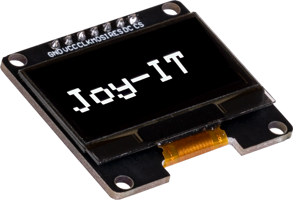
Image source: Joy-IT SBC-OLED01.3 Product Page
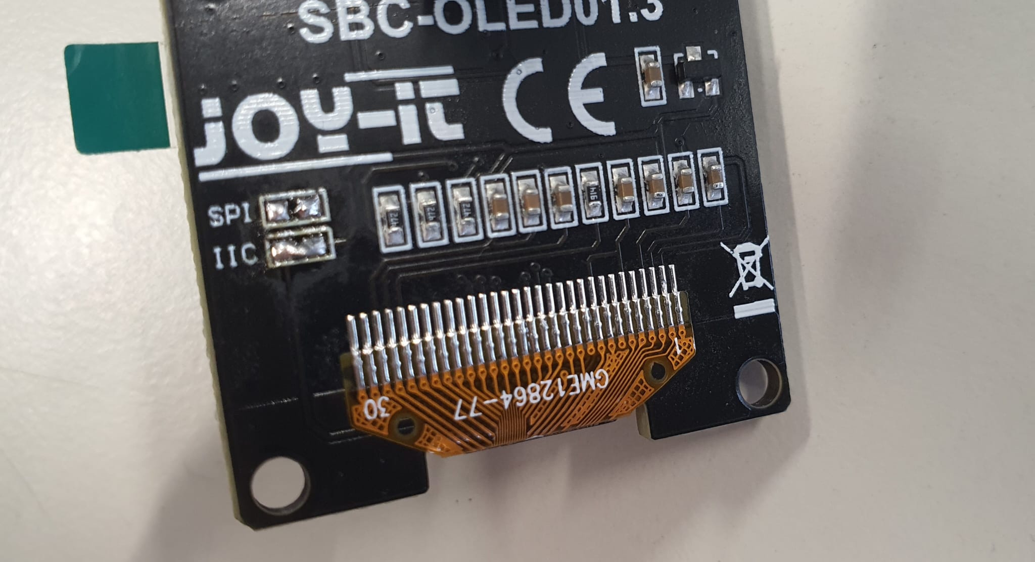
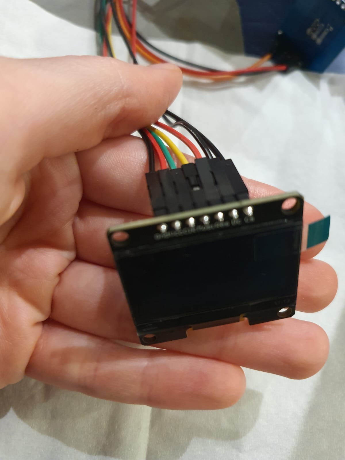
As seen in the picture, I desoldered the resistor on the backside of the display, and
connected the IIC by adding some soldering tin and connect it.
Testing SBC-OLED01.3 Integrity
Then I checked the datasheet
and Pi
Pico OLED arduino tutorial
to determine the required connections for the Pi Pico and the I2C communication protocol.
I figured that only Clk and Mosi pins need to be connected
for communicating. So I connected to Vcc to 3V3 net power from the Pi Pico, GND pin to
common GND, and the Mos pin to the default SDA pin on the Pi Pico (GPIO4) for transferring
data, and the Clk pin to the default SCL pin (GPIO5 of the Pi Pico) for synchronising data.
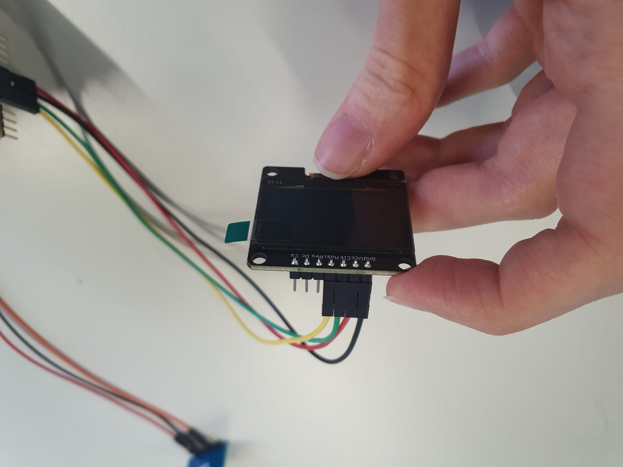
NOTE! The three pins left must be grounded as suggested in the datasheet;
which means pins Dc (Data/Command) and Cs (Chip Select) must be connected to GND and Res
(Reset) pin must be connected to 3v3. Although they are not required for I2C configuration,
grounding these pins is beneficial because it lowers floating pin noise and ensures steady
logic levels!
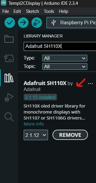
Additionally, I downloaded the library Adafruit SH110X from Arduino's
library manager, as it contains all the necessary files to test the example code.
Afterwards, following this datasheet,
I downloaded the code
example I2C and simplified it to double check whether it recognizes the device and
the right address
or not; otherwise, the display would be faulty.
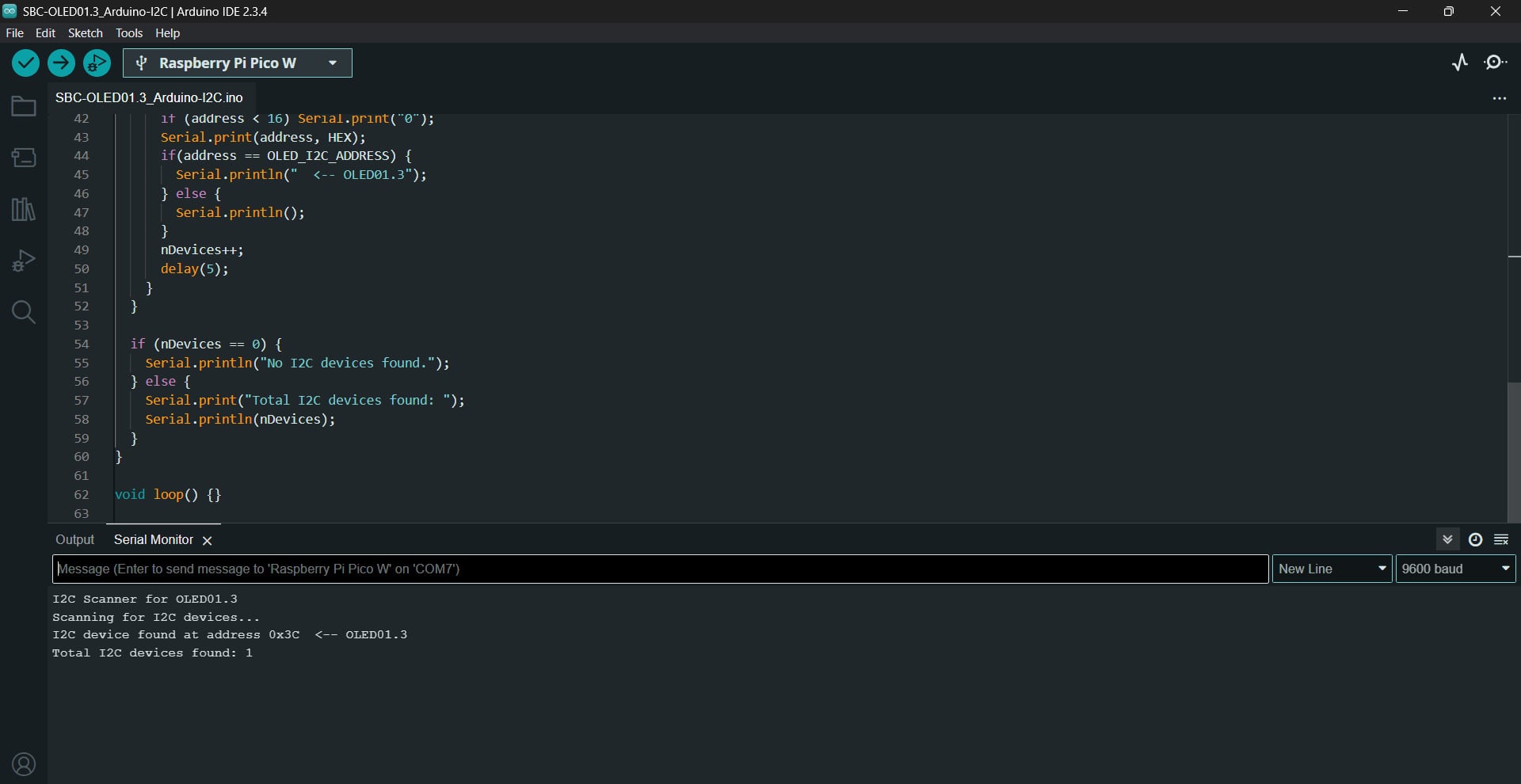
Scanning for I2C Address for the OLED01.3 Display Code
                                /*********************************************************************
                                EXAMPLE MODIFIED!

                                This is an example for our Monochrome OLEDs based on SH110X drivers

                                This example is for a 128x64 size display using I2C to communicate
                                3 pins are required to interface (2 I2C and one reset)

                                Adafruit invests time and resources providing this open source code,
                                please support Adafruit and open-source hardware by purchasing
                                products from Adafruit!

                                Written by Limor Fried/Ladyada  for Adafruit Industries.
                                BSD license, check license.txt for more information
                                All text above, and the splash screen must be included in any redistribution

                                i2c SH1106 modified by Rupert Hirst  12/09/21
                              *********************************************************************/

                              #include

                              #define OLED_I2C_ADDRESS 0x3C  // Expected address for OLED01.3

                              void setup() {
                                Serial.begin(9600);
                                while (!Serial); // Wait for Serial Monitor to open

                                Serial.println("I2C Scanner for OLED01.3");
                                Serial.println("Scanning for I2C devices...");

                                Wire.begin();  // Start I2C bus
                                delay(100);

                                byte error, address;
                                int nDevices = 0;

                                // Scan all possible I2C addresses
                                for(address = 1; address < 127; address++) {
                                  Wire.beginTransmission(address);
                                  error = Wire.endTransmission();

                                  if (error == 0) {  // Device responded
                                    Serial.print("I2C device found at address 0x");
                                    if (address < 16) Serial.print("0");
                                    Serial.print(address, HEX);
                                    if(address == OLED_I2C_ADDRESS) {
                                      Serial.println("  <-- OLED01.3");
                                    } else {
                                      Serial.println();
                                    }
                                    nDevices++;
                                    delay(5);
                                  }
                                }

                                if (nDevices == 0) {
                                  Serial.println("No I2C devices found.");
                                } else {
                                  Serial.print("Total I2C devices found: ");
                                  Serial.println(nDevices);
                                }
                              }

                              void loop() {}
Luckily, the address was found at 0x3C, thus, the functionality was confirmed!
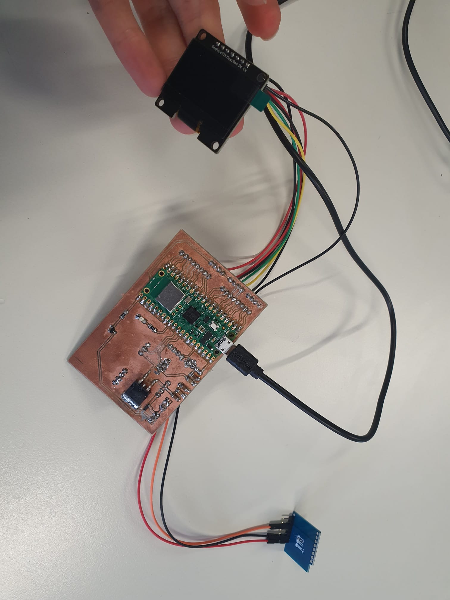
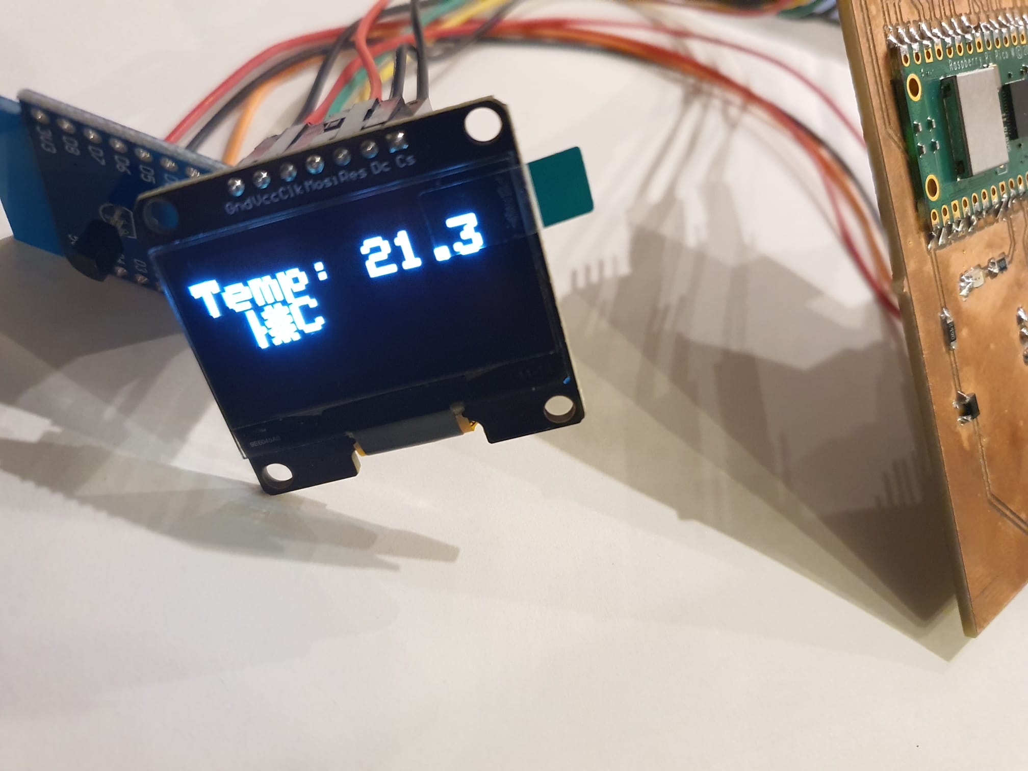
Testing OLED01.3 Display with DS18B20 Temperature Sensor
To experiment with printing the temperature value detected from the DS18B20 temperature
sensor module, I reconnected the same pins as mentioned in Input
Devices - Week 9
and developed the following code:
Reading Temperature on OLED01.3 Code
                                #include
                                    #include
                                    #include
                                    #include
                                    #include

                                    // I2C OLED Setup
                                    #define I2C_ADDRESS 0x3C
                                    #define SCREEN_WIDTH 128
                                    #define SCREEN_HEIGHT 64

                                    Adafruit_SH1106G display(SCREEN_WIDTH, SCREEN_HEIGHT, &Wire, -1);

                                    // DS18B20 Temperature Sensor Setup
                                    #define ONE_WIRE_BUS 27

                                    OneWire oneWire(ONE_WIRE_BUS);
                                    DallasTemperature sensors(&oneWire);

                                    void setup() {
                                      Serial.begin(9600);
                                      sensors.begin();

                                      // Initialize the I2C OLED display; reset = true
                                      if (!display.begin(I2C_ADDRESS, true)) {
                                        Serial.println(F("OLED not found"));
                                        while (1);  // Pause if OLED is not detected
                                      }

                                      // Display startup message
                                      display.clearDisplay();
                                      display.setTextSize(2);
                                      display.setTextColor(SH110X_WHITE);
                                      display.setCursor(0, 10);
                                      display.println("Starting...");
                                      display.display();
                                      delay(2000);
                                    }

                                    void loop() {
                                      // Request temperature from DS18B20
                                      sensors.requestTemperatures();
                                      float tempC = sensors.getTempCByIndex(0);

                                      // Print temperature to Serial Monitor
                                      Serial.print("Temperature: ");
                                      Serial.print(tempC);
                                      Serial.println(" °C");

                                      // Display temperature on the OLED
                                      display.clearDisplay();
                                      display.setTextSize(2);
                                      display.setCursor(0, 10);
                                      display.print("Temp: ");
                                      display.print(tempC, 1);  // Print with one decimal place
                                      display.println(" °C");
                                      display.display();

                                      delay(1000);
                                    }
As we can see the temperature is shown on the display correctly, hence, our wiring and code
are correct!
Testing with DC 12V fan and the Voltage Regulator
To verify the voltage regulator is soldered properly and regulates the desired voltages: one
leg has 12v coming in and the other leg has 5v going out, a multimelter was used.
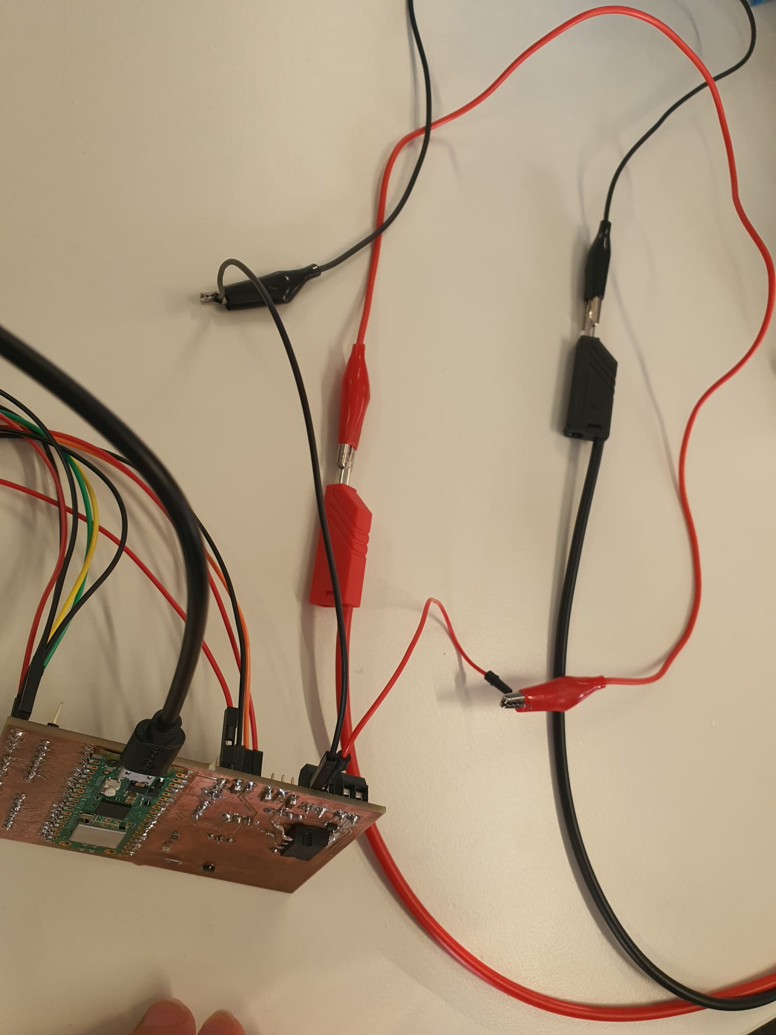
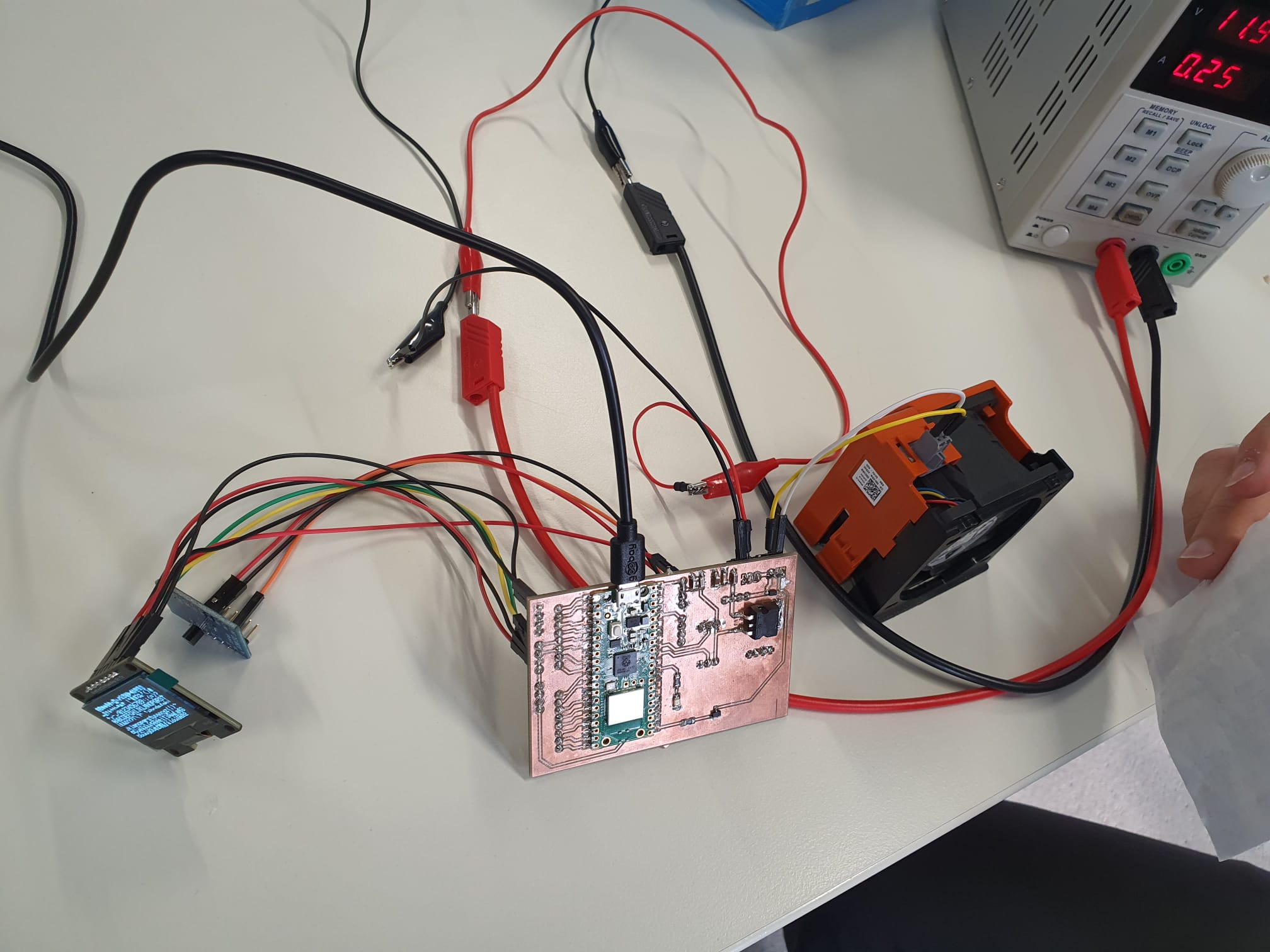
After we confirmed that the voltage regulator is connected properly, we went on with
testing
the second output device I will require for my:
the 12v DC fan.
For this, I connected the fan's pins to the dedicated connector terminals on the
PCB,
one pin was connected to common GND and the second was connected to 12v input.
To supply the circuit with 12v power, benchpower supply was connected and configered
at
~ 11.9 v and ~0.1 A current.
Afterwards, a simple Blink example code was connected and the "LED_BUILTIN" output
pin
was switched to pin 16, which corresponds to the mosfet pin in my schematic (for
more
details, see Electronics
Design - Week 6).
This mosfet in turn drives the fan; where the gate is connected to GPIO 16, drain is
connected to the FAN, and source to common GND.
Mosfet-Fan Circuit Testing Code
        /*
        Blink - Modified for Mosfet Testing


        Most Arduinos have an on-board LED you can control. On the UNO, MEGA and ZERO
        it is attached to digital pin 13, on MKR1000 on pin 6. LED_BUILTIN is set to
        the correct LED pin independent of which board is used.
        If you want to know what pin the on-board LED is connected to on your Arduino
        model, check the Technical Specs of your board at:
        https://www.arduino.cc/en/Main/Products

        modified 8 May 2014
        by Scott Fitzgerald
        modified 2 Sep 2016
        by Arturo Guadalupi
        modified 8 Sep 2016
        by Colby Newman

        This example code is in the public domain.

        https://www.arduino.cc/en/Tutorial/BuiltInExamples/Blink
      */

      // the setup function runs once when you press reset or power the board
      void setup() {
        // initialize digital pin Mosfet as an output.
        pinMode(16, OUTPUT); // Mosfet Gate
      }

      // the loop function runs over and over again forever
      void loop() {
        digitalWrite(16, HIGH);  // turn on Mosfet (HIGH is the voltage level)
        delay(1000);                      // wait for a second

      }
It worked! :) We can see how our fan makes the receipt paper fly!
Conclusion and Reflection
This week's assignment was alittle frustrating to complete yet worthwhile and
satisfying.
Among the challenges I faced were setting up the OLED01.3 display to run in I2C mode,
resolving conflicts between different libraries, finding out the I2C address, and
debugging connection problems.
Using the DS18B20 sensor to display temperature measurements required meticiluous
inspection in terms of hardware connections and code modifications.
By carefully reviewing datasheets of electronics, making iterative code changes, and
persistently debugging, I was finally able to reach my expected output values.
Files
- PCB Test Code - SBC-OLED0.1 Example Modified
- SBC-OLED01.3_Arduino-I2C_Modified.ino
- PCB Test Code - Temperature sensor + Display
- TempI2CDisplay.ino
- PCB Test Code - 12V DC Fan (Modified from Blink Example)
- MosfetFanTest.ino