Output Devise
Output devises are sensor that relay data from a micro-controller or computer to a hardware that can
either inform
the person through sound, light or a display.
This can also be a Mechanical function as well for instants a PC fan. To get a good reading we used
Lysander PCB
board and the PC fan what will be used in
his wind tunnel project. The fans manufacture states that at 12Volts it will consume a current of
0.295 Amps. To
test this we hooked the PCB Board to a lab power
supply. The Voltage was set to 12 volts and the Plus and Minus were hooked up to the input pins on
the board.
The next thing we did was test if the had indeed wired everything correctly, insuring that the fan
was than plugged
in correctly as well. Having done so we pushed the
switch on the power supply and checked if the board and fan would turn on.
Now that this was done we went ahead and talked about how best to measure the power consumption and
how to see if
the power being used by the PC fan was accurate.
To do this we used the formula P=V×I. We noted that P = Power in watts(W), V = Voltage in volts (V),
I = Current in
amperes (A) and that we want to find the
power being used. The math gave us the following result, P=12V×0.295A=3.54W. This was the
consumption with in one
hour. To find the what it used in one minute,
to check what he now usage was we simple did the following. Energy (wh) = Power (Watts) x Time in
minutes / 60min.
We wanted the closest value 1 min was was taken.
the result was that in one we were using O.059 Wh. Now looking at the read out of the power supply
we got 0.051 Wh.
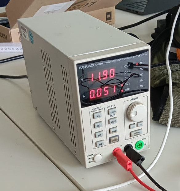
This was a good result. Now we needed to find out how much power the board was using. The fan was
removed and the
result was that the board was using so little current
that it could be completely neglected. Plugging the fan back in we looked at the amps the fan was
using once it was
up to speed. In the begins the fan used more power
to overcome the inertia. This can be compared to the moment you start riding a bicycle. The rider
needs to over come
this resistances. Once done so, the rider needs
less power to to keep moving. To find out if this was also the case we used the blink function for
the built-in LED
but for the fan. We increased the time to 5 seconds.
This gave the fan time to speed up and stop and speed up again. Giving us a good chance to see how
much the current
it was really using. Here we were also within the ballpark.
The current being used according to the power supply read 0.201 Amps, once it was up to speed. So
less than what the
fans maximum of 0.295 Amps.
The interesting thing to observer was the when we hooked in a multimeter between the board and the
fan to get the
power usage there. Below is a video that shows that
the fan once up to speed uses a lot less current. This was measured on the multimeter in mA and the
result was 0.175
mA.
As we can see the usage that we calculated earlier was pretty much dead on. If the need to repeat a
simple test, the
code can be looked at below as well as a simple
sketch that shows the setup.