Electronics Design
Group Assignment
- Use the test equipment in your lab to observe the operation of a microcontroller circuit board.
Individual Assignment
- Use an EDA tool to design a development board that uses parts from the inventory to interact and communicate with an embedded microcontroller.
This week I started experimenting with designing electronics using KiCad. Link to download: KiCad Download
Introduction
In this assignment, I designed a Printed Circuit Board (PCB) that integrates a Raspberry Pi Pico
(RP2040), and two LM35 temperature sensors I want to use for my final project.
First step was to install the fabacademy library
and adding the symbols and the footprints from our inventory. The Pico powers the circuit
with 3.3V, and the LM35 is powered from the same rail to ensure that its output (10 mV/°C) is
safely within the ADC range.
Additionally, mosfet was added to drive the fan as a practice for my final
project. This Mosfet was connected to GND, digital pin on the Pi Pico, and the third pin
was connected to the cathode side of a diode in order to protect the microcontroller.
The anode side was connected to the fan's negative side and then lastly the positive side of the
fan was connected to a 12v external power supply. To unite power supply, a voltage regulator is
added, with filtering capacitors in between, to step down voltage from 12v (for the fan) to 5v
(for the Pi Pico).
However, I haven't decided yet how to power the fan (using a power distribution system or a
breakout board) and which kind of fan. More research is needed. For this task, adding pinheaders
to represent all external components (fan, temperature sensors, 12v power supply) was
sufficient.
Moreover, OLED display was connected in order to show the temperature and the speed of the fans.
An extra LED is connected via a resistor to also indicate the fans state (On/OFF).
Circuit Overview
The circuit consists of the following components:
- Raspberry Pi Pico: Acts as the microcontroller, provides a stable 3.3V rail, and reads the analog temperature signal via its ADC.
- LM35 Temperature Sensor: Outputs a voltage proportional to temperature (10 mV/°C). Its V+ and GND are connected to the Pico's 3.3V and common GND, respectively, while its output is routed to an ADC pin (e.g., GPIO26/ADC0).
- NDS355A Mosfet/ Transistor : Used as a low-side switch to drive the fan (its gate driven by GPIO 16, drain connected to the FAN, and source to common GND).
- Diode 1N4001Soldered on the PCB, connected between the 12V supply and the MOSFET drain to protect the mosfet against inductive voltage spikes.
- OLED Display to display both the current detected temperature and the speed of the fan.
- DC Fanto cool down my laptop once overheated
- Linear Voltage Regulator DPAK to step down voltage from 12v to 5v
Schematic Design in KiCad
Project Setup
Create a new KiCad project, name it "PicoTempFan", save locally. Open the schematic editor.
Create a new KiCad project, name it "PicoTempFan", save locally. Open the schematic editor.
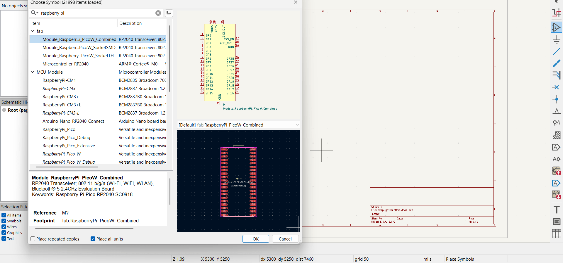
Place the Raspberry Pi Pico
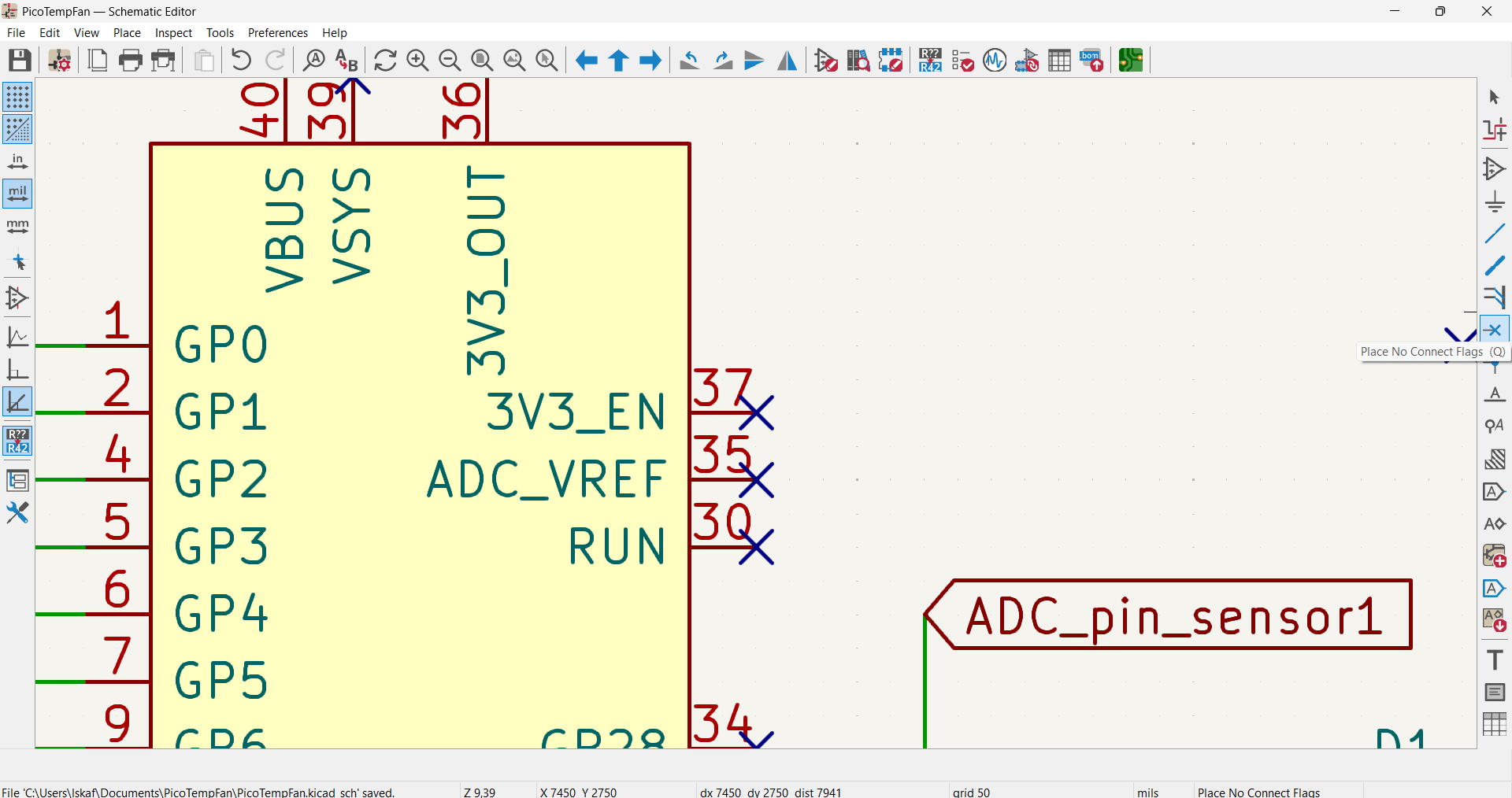
Place the Raspberry Pi Pico symbol from symbol library (or shortcut A). Ensure its power pins
(3V3 and GND) are connected to a 3.3V net, and that unused I/O pins are crossed using
Place No Connect Flags from the toolbar. This way, I can avoid errors when I
run Electrical Rules Checker
Place Two LM35 Temperature Sensors
Add two LM35 symbols (Shortcut A). Wire each V+ to 3.3V, GND to the common ground, and output to
ADC pins on the Pico > GPIO26 and GPI27.
Place the Mosfet
Add mosfet symbol (Shortcut A). Connect source (s) to common GND, Gate (G) to the digital pin
GPIO 15, via a 100 Ohm resistor. Then, connect the drain (D), through a diode for protection, to
the negative side of the fan. The second pin of the fan is connected to 12v external power.
Place the voltage regulator
Add mosfet symbol (Shortcut A). Connect source (s) to common GND, Gate (G) to the digital pin
GPIO 15, via a 100 Ohm resistor. Then, connect the drain (D), through a diode for protection, to
the negative side of the fan. The second pin of the fan is connected to 12v external power.
Place the OLED display
The OLED Display has 4 pins: Vcc to power the display, SDA to transfer the actual data, SCL
(clock signal) to synchronize the data transfer, and a common GND pin. Hence, for the
schematic,any exposed pin could work to assign the I²C communication protocol. For this task, I
selected the default pins, which are GPIO4 for SDA and GPIO5 for SCL.
Connections and Wiring
- The 3.3V net (from the Pico's 3V3 pin) powers LCD.
- The 5v powers LM35 sensors. The output pins are labeled “ADC_pin_sensor1” or “ADC_pin_sensor2” and connected to the corresponding ADC pins; GPIO27 and GPI26. respectively
- The 12V net is labeled as 4 external pins to represent the power source for driving the fans.
- The linear voltage regulator is add to step down from 12v (for the fan) to 5v (for the microcontroller)
- The 3.3V net and common GND are also represented as 4 pinheaders also to avoid the common error of Input power pin not driven by any output power pins
- A test LED is also connected: the cathode side to the common GND and the anode side to GPIO22 pin via a resistor
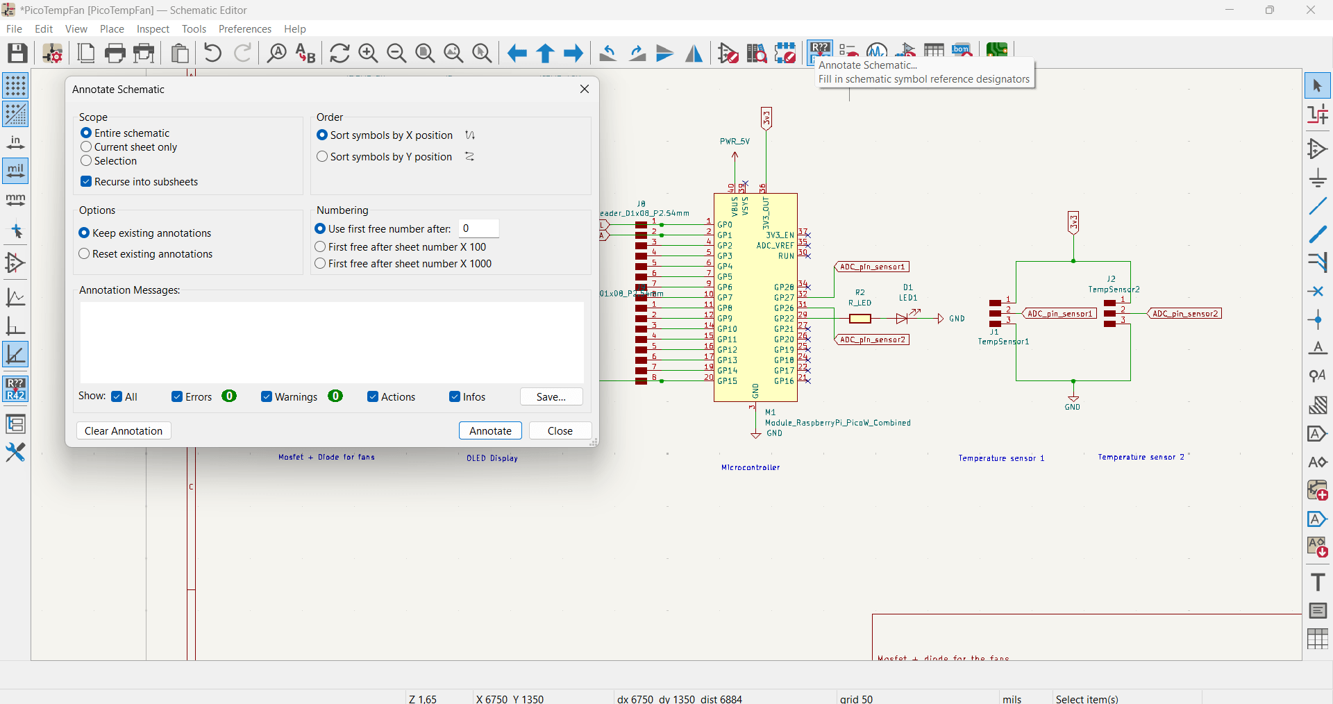
Annotate Schematic and Electrical Rules Check (ERC)
To ensure that all schematic symbol reference designators are filled in, click Annotate
Schematic from the toolbar and click "ok". Afterwards, run the ERC
to ensure all nets are correctly connected. Add PWR_FLAG symbols if KiCad complains about power
nets not being driven. Then, assign appropriate footprints to your components using the CvPcb
tool.
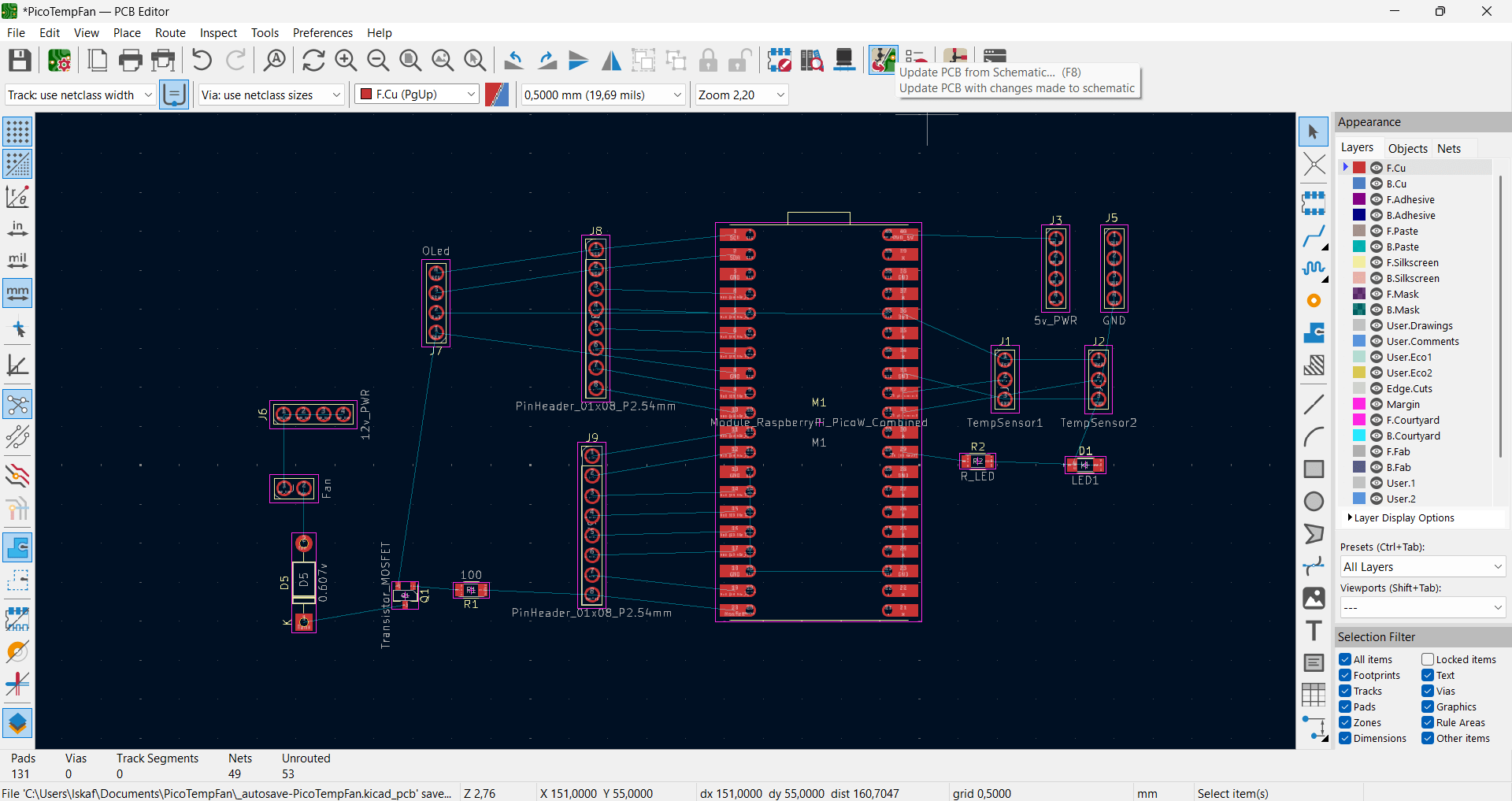
Transition to PCB Layout
Click the Updabte PCB schematic button to project the schematic onto the PCB
editor workspace. Then, organize the components in a logical manner. Route the cables using the
Route Single Track tool to connect the components. For the track, edit the
net class width to be 0.4 mm.
Make sure to follow the PCB design rules (e.g. clearance rules) and assign the correct
footprints.
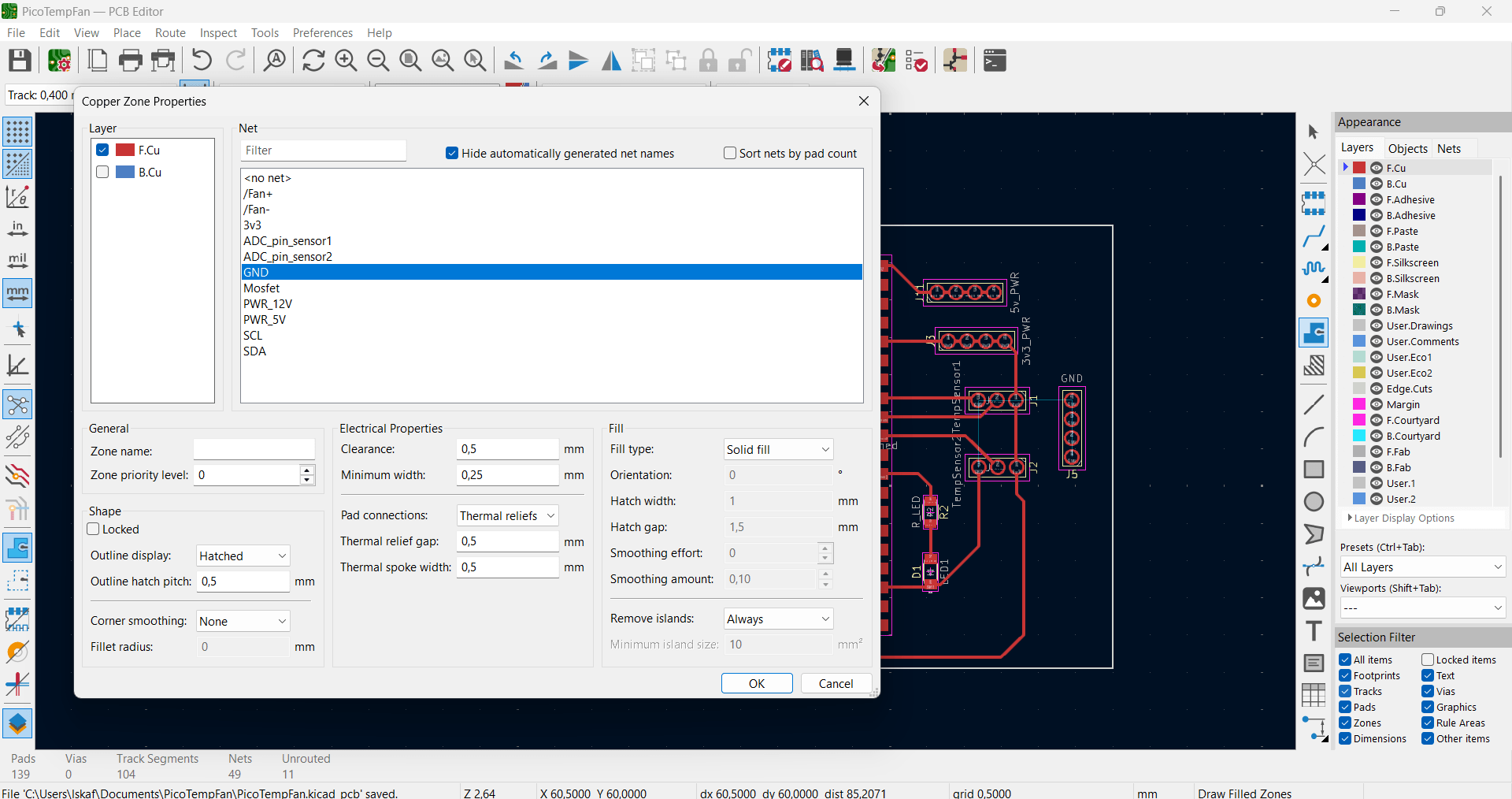
After arrangement and check is done, draw a rectangle around the PCB. Now, press E for
properties then check cut edgesto outline the outer frame of the PCB. Then, use
the Draw Filled Zones function for the GND layer, then press B
to create the copper zone and make and make sure everything is connected.
Generating Gerber and Drill files
After completing the PCB layout, run the Design Rule
Checker (DRC) from the toolbar and generate Gerber files. In order to check
how the PCB looks in 3D, use the 3D Viewer tool. Once done, Gerbers files can
be generated.
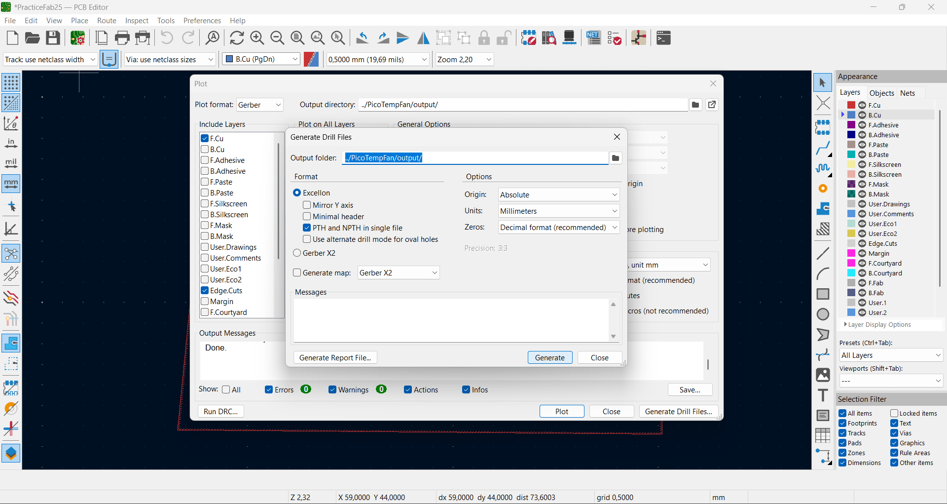
This can be done by going to Files > Fabrication Output > Gerbers
(.gbr) For this assignment, everything can be left to default and layers checks on
F.Cu and cut edges are sufficient. Now, click generate
drill files to generate files. After saving the Gerbers .zip files, they can be
viewed using the Gerber Viewer to check integrity and accuracy before sending
it to the manufacturer.
Now, the Gerber files are ready to be sent to the PCB producer.
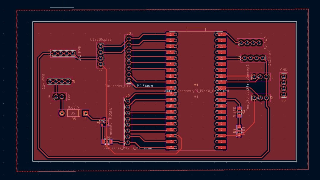
Final PCB View
Conclusion and Reflection
This schematic design uses a Raspberry Pi Pico as the microcontroller, an LM35 sensor to measure
temperature, and a Mosfet to drive the fans via 12 external power source. An OLED display is
used to show the current temperature and the speed of the fan. All components are powered from
the 3.3v, excpet for the fan; external power source of 12v is needed.
Therefore, a voltage regulator will be used to step down voltage from 12 v (fan) to 5 v (Pi Pico
w), hence, unify the power source for all electronics.
Overall, using KiCAD for the first time was abit frustrating and overwhelming, overcoming the
errors and connecting the components on the PCB editor was challenging. Therefore, I will need
to practice designing simple boards more to be faster and more confident with the whole process.
YouTube Tutorials:
- KiCAD 7 PCB Layout in 5 steps
- KiCad 7 ESP32 PCB Design Full Tutorial - made by morten laboratories iot-thing
- Master New KiCad 7 In Under 2 Hours | #PCBCUPID
Files
- KiCAD project
- PicoTempFan.zip