Input Devices
Group Assignment
- Probe an input device's analog levels and digital signals.
Individual Assignment
- Measure something: add a sensor to a microcontroller board that you have designed and read it.
For this week, I attempted to use an DS18B20 shield as my input device to check whether I still need to order LM35 temperature sensor for my LapTable
DS18B20 Temperature Sensor Module Measurement Module
Image source: DS18B20 Sensor Module – Indian HobbyCenter
D1 Mini DS18B20
Shield is a digital thermometer that can measure temperatures accurately over range
of -55°C to +125°C, With an accuracy of ±0.5°C between -10°C and +85°C.
It connects to a central CPU via a 1-Wire bus, which only needs a ground connection and one
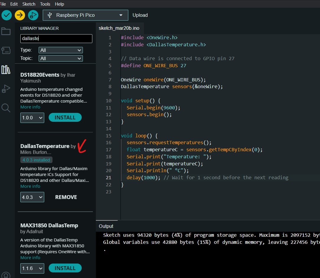
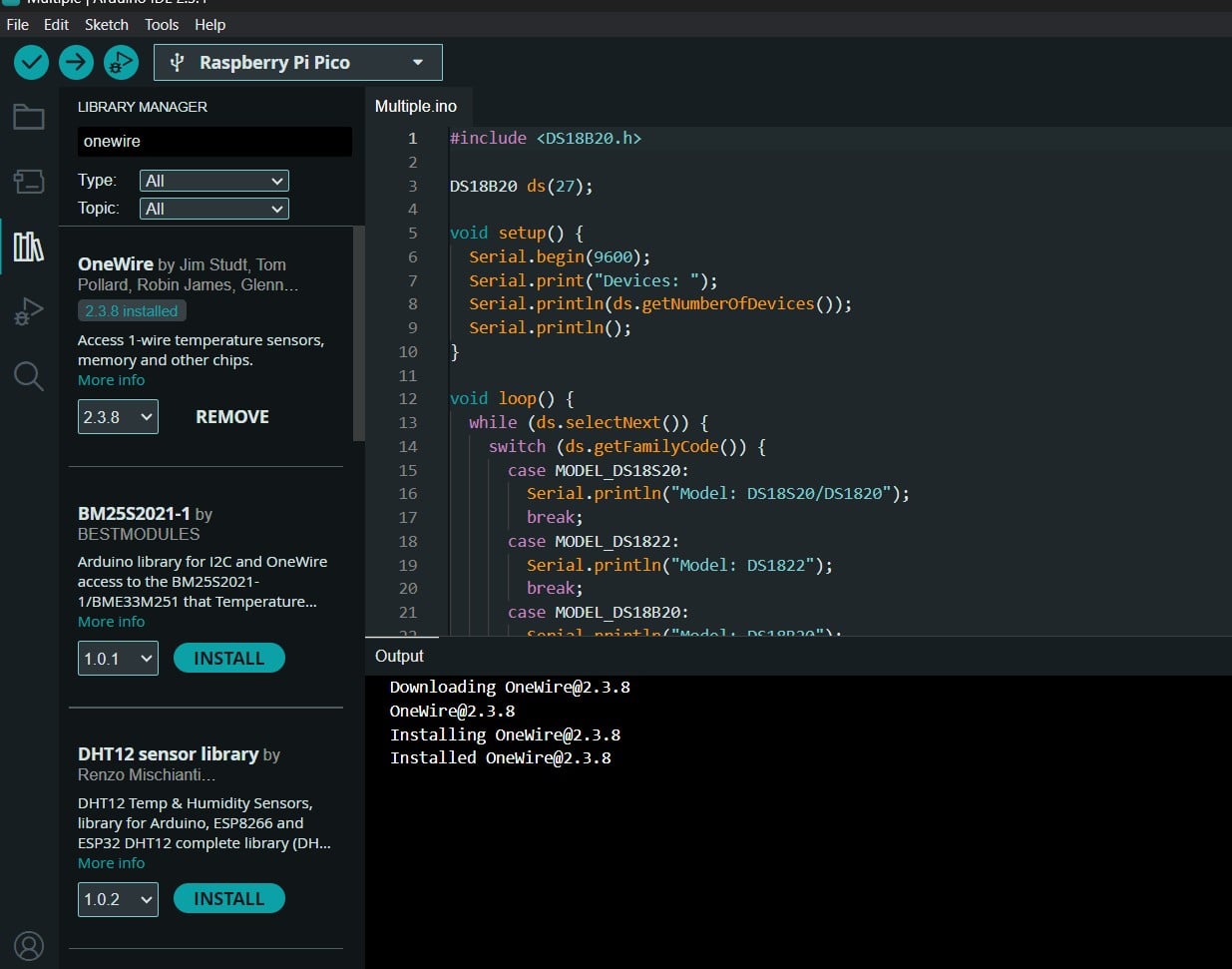
data line. In order to test it, I modified example code from the libraries OneWire and
Dallas Temperature.
For more information, find the datasheet here!.
DS18B20 Sensor Test with my personal PCB
I linked the DS18b20 to pinheaders I soldered on the board I produced in Week8-
Electronics Production. One pin is connected to common GND, one pin is connected to
5V, and the third one is connected to GPIO 27 (output).
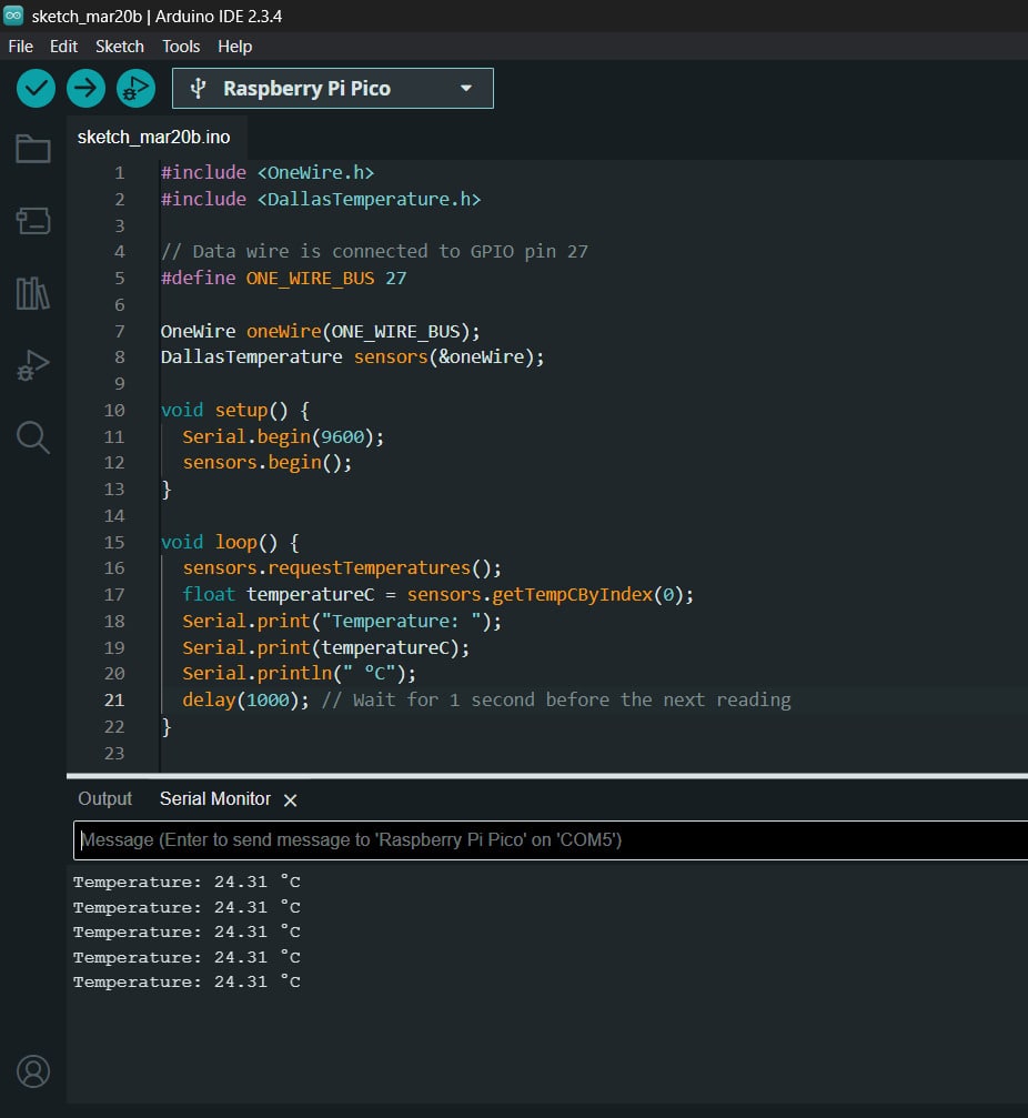
In ArduinoIDE, I ran the code example
single from the library and I read the temperature on the serial monitor in Celsius
degrees.I figured it was roughly around room temperature (~24°C).
Arduino Code
                               *#include
                                #include

                                // Data wire is connected to GPIO pin 27
                                #define ONE_WIRE_BUS 27

                                OneWire oneWire(ONE_WIRE_BUS);
                                DallasTemperature sensors(&oneWire);

                                void setup() {
                                  Serial.begin(9600);
                                  sensors.begin();
                                }

                                void loop() {
                                  sensors.requestTemperatures();
                                  float temperatureC = sensors.getTempCByIndex(0);
                                  Serial.print("Temperature: ");
                                  Serial.print(temperatureC);
                                  Serial.println(" °C");
                                  delay(1000); // Wait for 1 second before the next reading
                                }
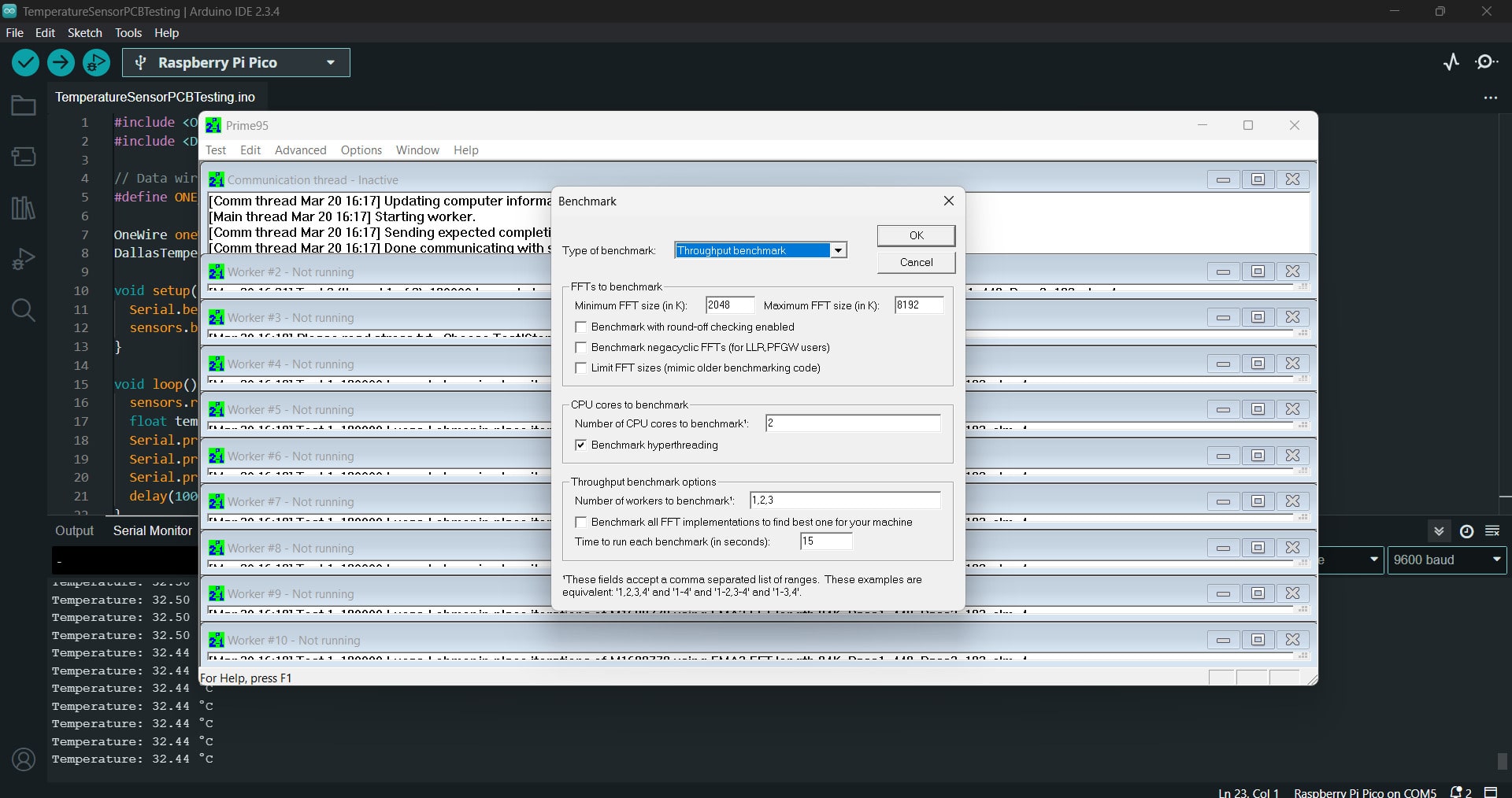
Stress and Benchmark Test
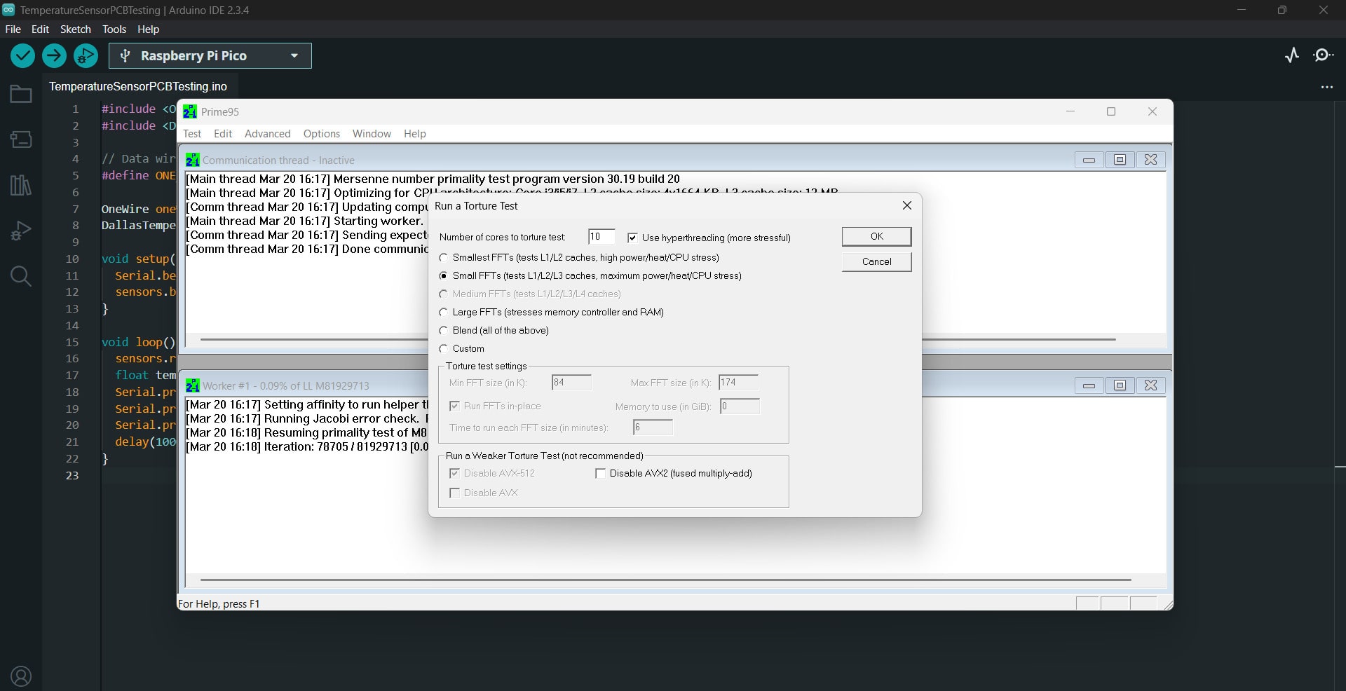
However, in order to push the laptop to its limit, Using Prime95, I conduct a stress test for the
CPU to determine how hot my laptop gets. A stress test is a process that deliberately pushes
the computer system beyond its normal operational capacity to evaluate its stability and
identify its weaknesses.
This will help me determine more precisely what kind of fans I will eventually need and
where to mount the temperature sensors for the most accurate temperature reading when the
laptop is stressed while using multiple softwares simultaneously that require high CPU
performance.
From the Prime95 options, I selected torture test and I ticked on
Small FFTs to push the laptop to the limits. Then, Pressed ok and ran the
test. I repeated the same process but with a throughput benshmark test.
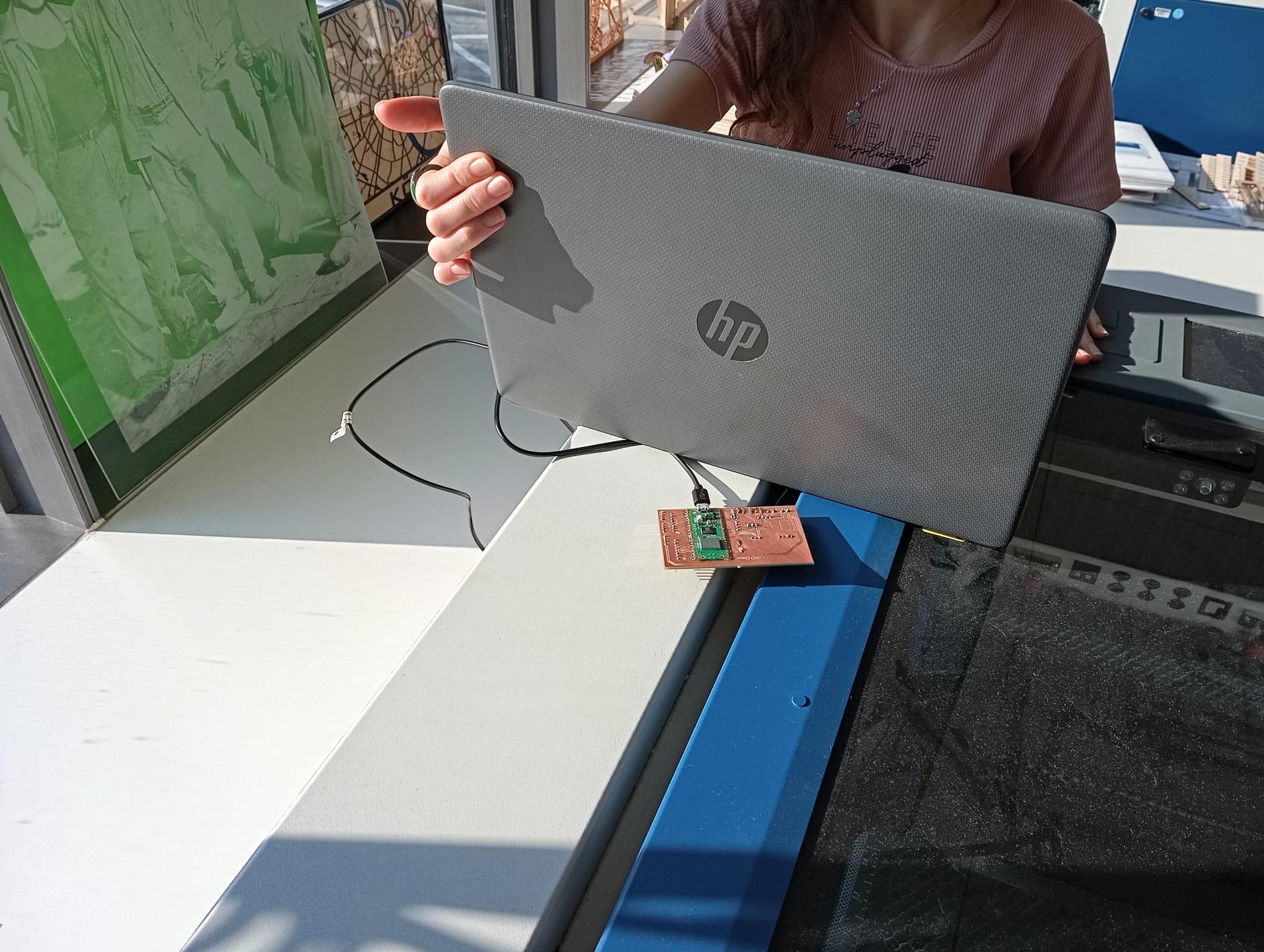
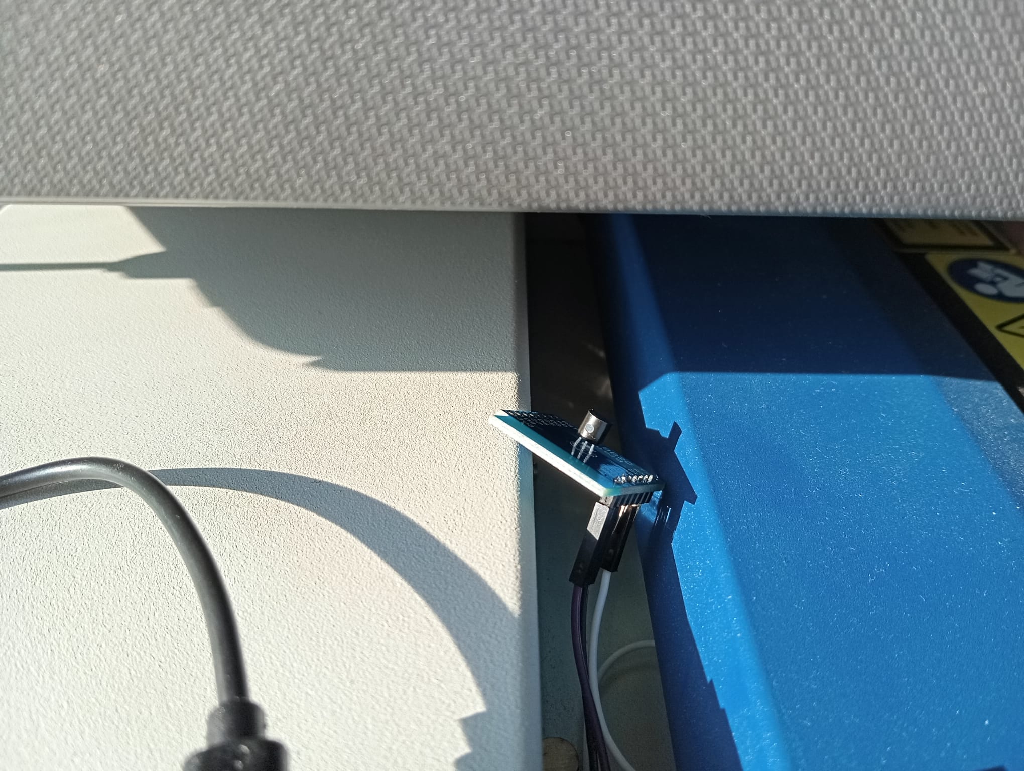
 To amplify even more, I placed my setup under the sun and fixated the temperarure sensor on
the laser cutter under the laptop, where the CPU is placed (middle upper section of the
laptop's bottom surface)
To amplify even more, I placed my setup under the sun and fixated the temperarure sensor on
the laser cutter under the laptop, where the CPU is placed (middle upper section of the
laptop's bottom surface)
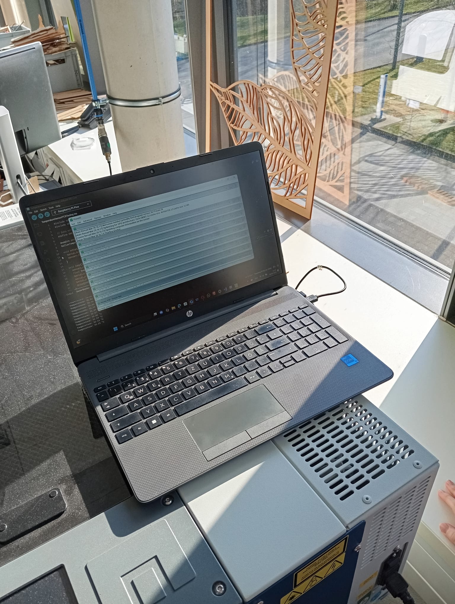
Reading the temperature on the Serial Monitor, I noticed how it raised up to 33°C. This
means that the sensor in fact detected the impact of the sun, as well as the stress and
benchmark test on the heat of the laptop's CPU.
Comparison to HWMonitor
Nevertheless, this can be considered still safe temperatures, as it is still under 70°C
(see:
Normal CPU Temperature). Therefore, I need to find a way to measure the actual
internal temperature of the CPU and turn on the fans for my final project accordingly.
Therefore, I used H HWMonitor to
determine what is the actual heat laptop reaches when under pressure. Comparing to
temperature monitored via HWMonitor I performed in Stress
Test Laptop's CPU - Week 6,
I found out that P-cores (performance Cores) max temperature to be 69°C, and the E-Cores
(Efficiency Cores) Max Tempemperature to be 66°C.
This means that my laptop's CPU is still in the safe zone; remaining under 70°C.
However, the heat on the bottom suface is still visible and working with softwares such
as Fusion360 requires constant monitoring and controlling to keep temperature under 70°C
and to prevent thermal throttling to maintain standard performance.
Thus, I theoretically should set up the threshold of the temperatures detected to be
70°C for the fan to turn on and cool the CPU down.
Next Step - Copper Pad
Using copper pad (~20 × 20 mm) can greatly increase thermal conductivity between the
heat source (CPU) and the sensor (LM35), which improves the accuracy of temperature
measurement from the laptop's bottom surface.
This can be place somehow flushed in the bottom middle surface of the table, so it has
consistent contact with the laptops bottom surface and fixate the temperature sensor on
it.
This still has to be tested once the fan and the temperature sensors are ready, and the
design of the table is modified accordingly.
Conclusion and Reflection
The project for this week helped me better understand input devices and how they are
used in embedded systems in the real world. Using my custom-designed PCB and the DS18B20
digital temperature sensor, I was able to correctly read and interpret temperature
information through an Arduino IDE code.
Furthermore, benchmarking and stress testing the laptop helped me understand realistic
thermal loads and how surface temperature may be greatly impacted by outside factors
like sunshine.
I was able to determine the sensor's limitations and the significance of utilizing a
copper pad or thermal interface to enhance contact and accuracy by comparing the DS18B20
data with internal diagnostics from HWMonitor.