Analog and Digital with the oscilloscope
To probe digital and analog input we used three sensors: DHT22 for temperature and humidity, HC-SR04 for measuring distance through ultrasonic sound waves, and MH infrared tracker
DHT22
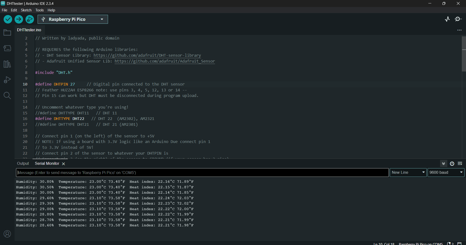
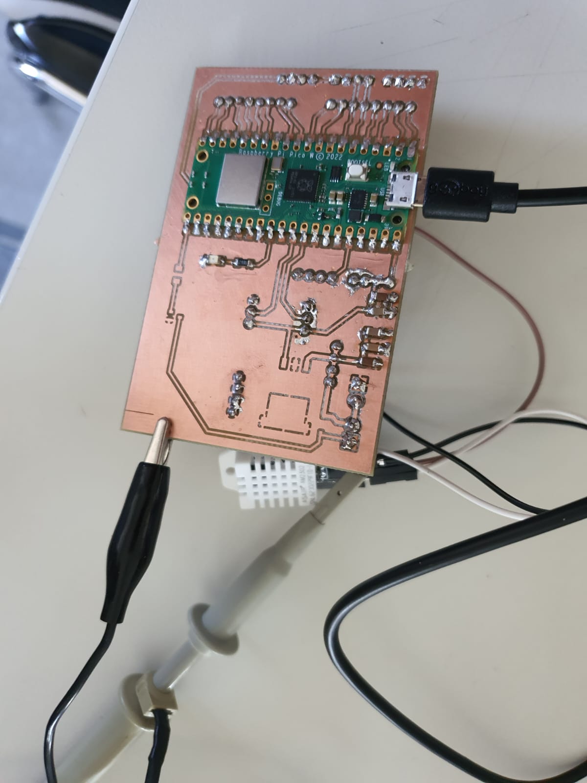
Using the example sketch from the DHT22 library in ArduinoIDE, we connected the DHT22 to the microcontroller (PCB with Raspberry Pi Pico on it) and read the temperature and humidity by connecting one pin to GND, one pin to 5v, and the third to a digital output pin (pin27). Checking the serial monitor, we confirmed that the connections are correct and humidity reads 30% and temperature ~23 °C. An oscilloscope was used to visualize the digital signal from the sensor, which was a timed series of pulses that represent bits.
                    // Example testing sketch for various DHT humidity/temperature sensors
                    // Written by ladyada, public domain

                    // REQUIRES the following Arduino libraries:
                    // - DHT Sensor Library: https://github.com/adafruit/DHT-sensor-library
                    // - Adafruit Unified Sensor Lib: https://github.com/adafruit/Adafruit_Sensor

                    #include "DHT.h"

                    #define DHTPIN 27     // Digital pin connected to the DHT sensor
                    // Feather HUZZAH ESP8266 note: use pins 3, 4, 5, 12, 13 or 14 --
                    // Pin 15 can work but DHT must be disconnected during program upload.

                    // Uncomment whatever type you're using!
                    //#define DHTTYPE DHT11   // DHT 11
                    #define DHTTYPE DHT22   // DHT 22  (AM2302), AM2321
                    //#define DHTTYPE DHT21   // DHT 21 (AM2301)

                    // Connect pin 1 (on the left) of the sensor to +5V
                    // NOTE: If using a board with 3.3V logic like an Arduino Due connect pin 1
                    // to 3.3V instead of 5V!
                    // Connect pin 2 of the sensor to whatever your DHTPIN is
                    // Connect pin 3 (on the right) of the sensor to GROUND (if your sensor has 3 pins)
                    // Connect pin 4 (on the right) of the sensor to GROUND and leave the pin 3 EMPTY (if your sensor has 4 pins)
                    // Connect a 10K resistor from pin 2 (data) to pin 1 (power) of the sensor

                    // Initialize DHT sensor.
                    // Note that older versions of this library took an optional third parameter to
                    // tweak the timings for faster processors.  This parameter is no longer needed
                    // as the current DHT reading algorithm adjusts itself to work on faster procs.
                    DHT dht(DHTPIN, DHTTYPE);

                    void setup() {
                    Serial.begin(9600);
                    Serial.println(F("DHTxx test!"));

                    dht.begin();
                    }

                    void loop() {
                    // Wait a few seconds between measurements.
                    delay(2000);

                    // Reading temperature or humidity takes about 250 milliseconds!
                    // Sensor readings may also be up to 2 seconds 'old' (its a very slow sensor)
                    float h = dht.readHumidity();
                    // Read temperature as Celsius (the default)
                    float t = dht.readTemperature();
                    // Read temperature as Fahrenheit (isFahrenheit = true)
                    float f = dht.readTemperature(true);

                    // Check if any reads failed and exit early (to try again).
                    if (isnan(h) || isnan(t) || isnan(f)) {
                        Serial.println(F("Failed to read from DHT sensor!"));
                        return;
                    }

                    // Compute heat index in Fahrenheit (the default)
                    float hif = dht.computeHeatIndex(f, h);
                    // Compute heat index in Celsius (isFahreheit = false)
                    float hic = dht.computeHeatIndex(t, h, false);

                    Serial.print(F("Humidity: "));
                    Serial.print(h);
                    Serial.print(F("%  Temperature: "));
                    Serial.print(t);
                    Serial.print(F("°C "));
                    Serial.print(f);
                    Serial.print(F("°F  Heat index: "));
                    Serial.print(hic);
                    Serial.print(F("°C "));
                    Serial.print(hif);
                    Serial.println(F("°F"));
                    }
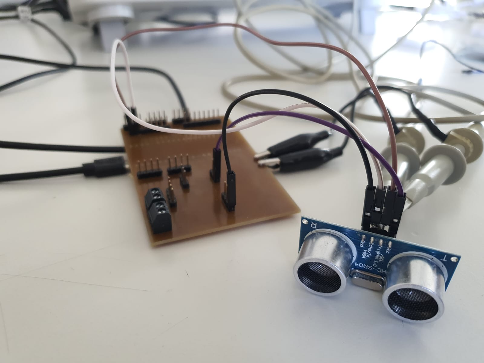
HC-SR04 Ultrasonic Sensor
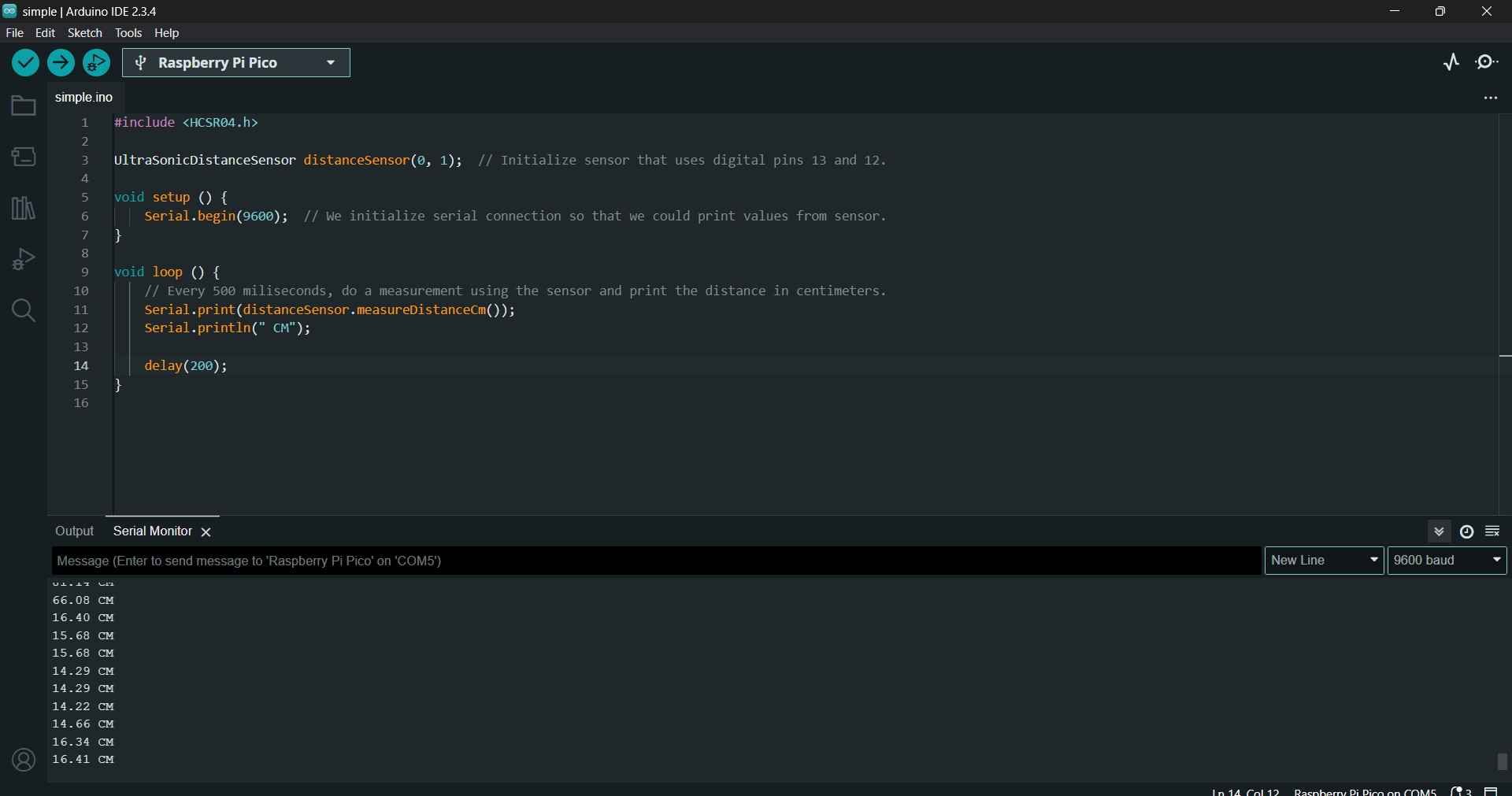
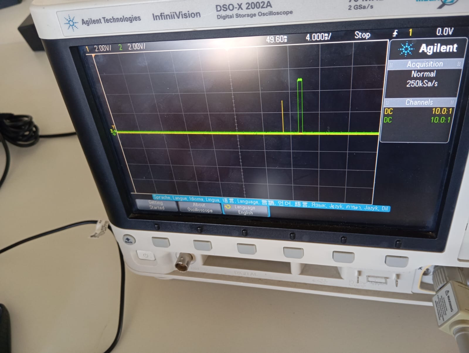
We created a sketch for the HC-SR04 that delivers a continuous trigger pulse and gauges the width of the echo pulse that is returned. There is a correlation between the echo width and distance (about 1.765 ms for 31 cm and 974 µs for 16 cm). We were able to confirm the distance estimate because the oscilloscope showed both the variable echo (green channel) and the fixed trigger (yellow channel).
                    #include

                    UltraSonicDistanceSensor distanceSensor(0, 1);  // Initialize sensor that uses digital pins 13 and 12.

                    void setup () {
                        Serial.begin(9600);  // We initialize serial connection so that we could print values from sensor.
                    }

                    void loop () {
                        // Every 500 miliseconds, do a measurement using the sensor and print the distance in centimeters.
                        Serial.print(distanceSensor.measureDistanceCm());
                        Serial.println(" CM");

                        delay(200);
                    }
MH Infrared Tracker
For this sensor we compared how digital and analog signals differed using the oscilloscope. As shown in the video, the green line jumping from 0 to 5V represents the digital output (discrete data), whereas the yellow line going up and down smoothly in small steps represents the analog output (continuous data).
Logic Analyzer
In order to interpret serial data, we used a logic analyzer. We
connected Raspberry Pi Pico W with pins 11 and 12 (GPIO 8 and 9) to output asynchronous serial data
(channel 2) and a PWM signal (channel 4). We downloaded the software Logic to capture the readout signals.
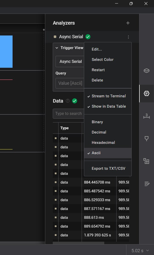
Channel D2 displays "Hello World" broadcasts every second when the analyzer is configured to Async Serial at 9600 baud with ASCII output.
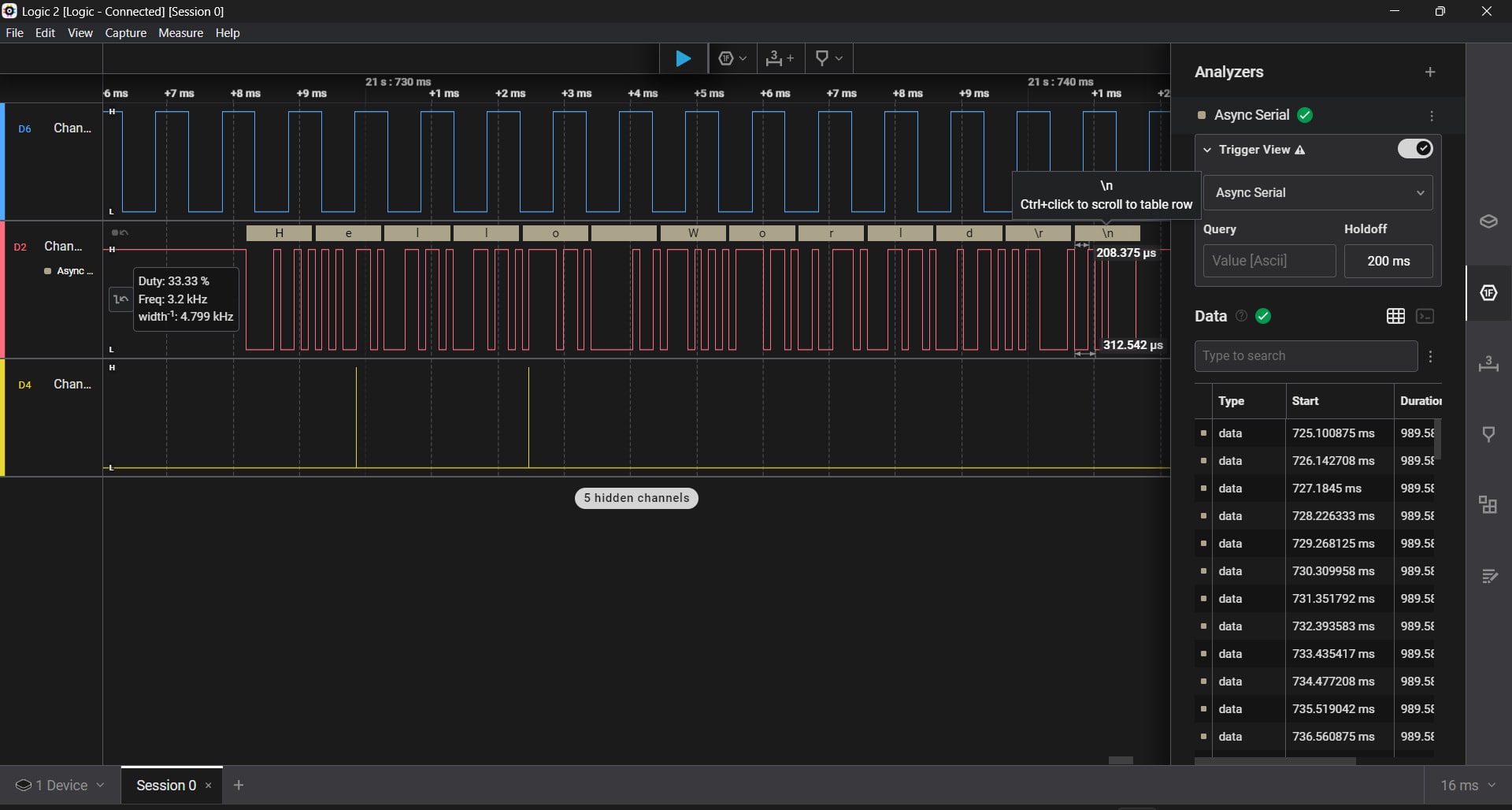
Channel D4 displays a 50% duty cycle PWM wave that is produced by writing a value of 127 (out of 255) to analogOutPin.
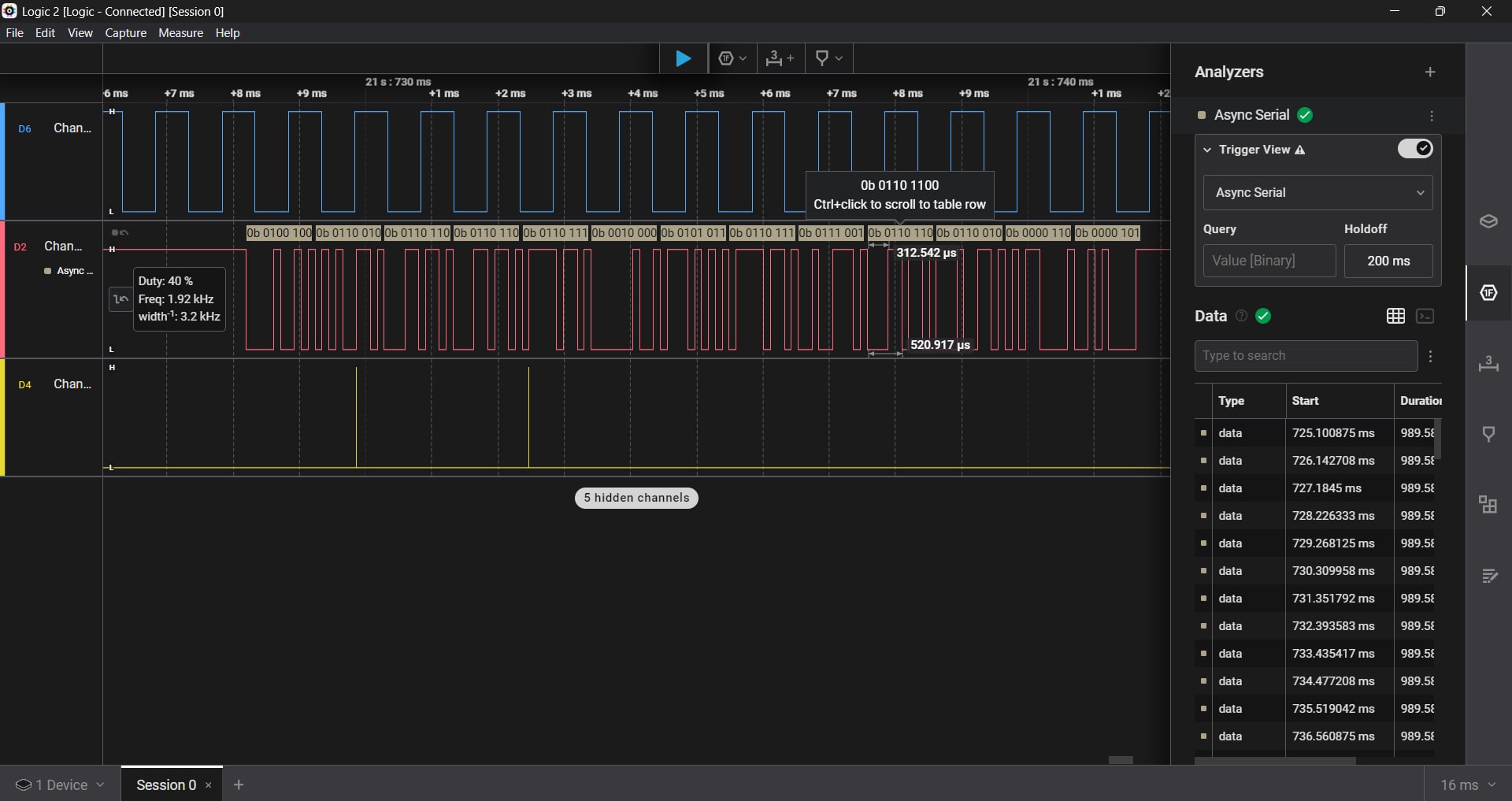
With flush operations clearing the serial stream, the data verifies continuous 1s and 0s based on signal width. It also shows intervals where data is transmitted (2s) and then idle (1s). Furthermore, we can see the timing of the PWM and the serial output in real time by showing how each character is decoded using timestamps.
                    /*
                    Analog input, analog output, serial output

                    Reads an analog input pin, maps the result to a range from 0 to 255 and uses
                    the result to set the pulse width modulation (PWM) of an output pin.
                    Also prints the results to the Serial Monitor.

                    The circuit:
                    - potentiometer connected to analog pin 0.
                        Center pin of the potentiometer goes to the analog pin.
                        side pins of the potentiometer go to +5V and ground
                    - LED connected from digital pin 9 to ground through 220 ohm resistor

                    created 29 Dec. 2008
                    modified 9 Apr 2012
                    by Tom Igoe

                    This example code is in the public domain.

                    https://www.arduino.cc/en/Tutorial/BuiltInExamples/AnalogInOutSerial
                    */

                    const int analogOutPin = 2;  // Analog output pin that the LED is attached to


                    void setup() {
                    // initialize serial communications at 9600 bps:
                    Serial2.begin(9600);

                    }

                    void loop() {
                    // read the analog in value:

                    analogWrite(analogOutPin, 127);

                    // print the results to the Serial Monitor:

                    Serial2.print("Hello World");

                    // wait 2 milliseconds before the next loop for the analog-to-digital
                    // converter to settle after the last reading:
                    delay(1000);

                    }
                    /*
                    Blink

                    Turns an LED on for one second, then off for one second, repeatedly.

                    Most Arduinos have an on-board LED you can control. On the UNO, MEGA and ZERO
                    it is attached to digital pin 13, on MKR1000 on pin 6. LED_BUILTIN is set to
                    the correct LED pin independent of which board is used.
                    If you want to know what pin the on-board LED is connected to on your Arduino
                    model, check the Technical Specs of your board at:
                    https://www.arduino.cc/en/Main/Products

                    modified 8 May 2014
                    by Scott Fitzgerald
                    modified 2 Sep 2016
                    by Arturo Guadalupi
                    modified 8 Sep 2016
                    by Colby Newman

                    This example code is in the public domain.

                    https://www.arduino.cc/en/Tutorial/BuiltInExamples/Blink
                    */

                    // the setup function runs once when you press reset or power the board
                    void setup() {
                    // initialize digital pin LED_BUILTIN as an output.
                    pinMode(9, OUTPUT);
                    }

                    // the loop function runs over and over again forever
                    void loop() {
                    digitalWrite(9, HIGH);  // turn the LED on (HIGH is the voltage level)
                    delay(500);                      // wait for a second
                    digitalWrite(9, LOW);   // turn the LED off by making the voltage LOW
                    delay(500);                      // wait for a second
                    }