
4. Embedded Programming
Assignment
Group assignment:
- Demonstrate and compare the toolchains and development workflows for available embedded architectures
- Document your work to the group work page and reflect on your individual page what you learned
Individual assignment:
- Browse through the datasheet for your microcontroller
- Write a program for a microcontroller, and simulate its operation, to interact (with local input &/or output devices) and communicate (with remote wired or wireless connection)
Learning outcomes
- Implement programming protocols.
Group Assignment
This is a link of this week's group assignment.→ Group assignment
Individual Assignment
Browse the datasheets
I checked several microcontrollers' datasheets as follows;
- RP2040
- ESP32
RP2040
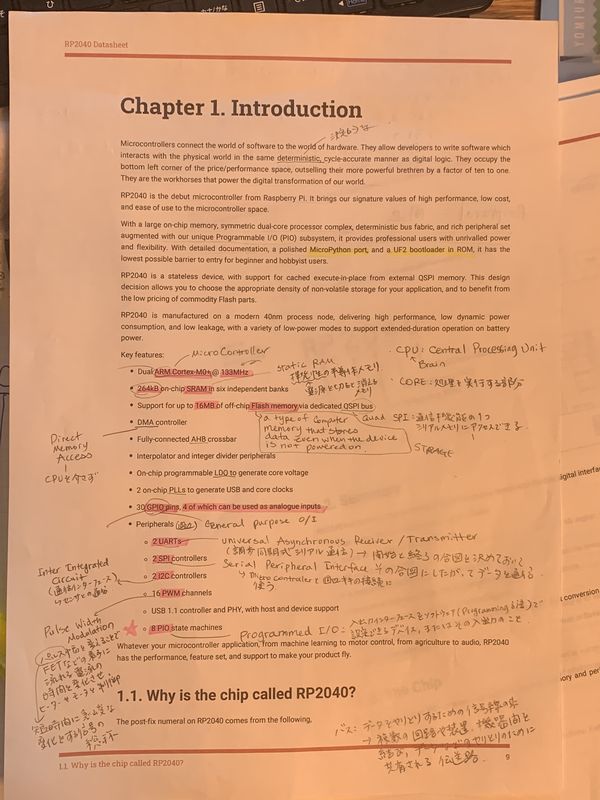
I read RP2040 datasheet.
First of all, there are so many unknown words to read a datasheet.
So I made a words list(dictionary) for understanding.
Basic summary of RP2040 is as follows;
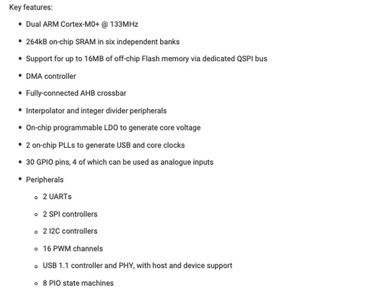
In RP2040, it has 2 processors(ARM Coretex-M0+) and which speed is up to 133MHz.
Also 264kb SRAM(on-chip) in six independent banks.
AS it has also 30 GPIO pins and 4 of which can be used as analog input,
this controller can be used for my final project.
My final project needs color controller(analog changing) for lights.
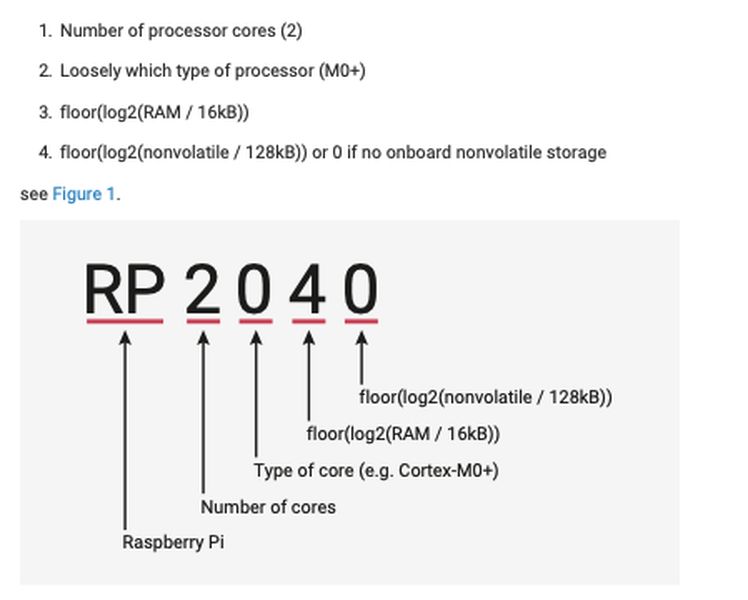
Each letter of the name has a meaning.
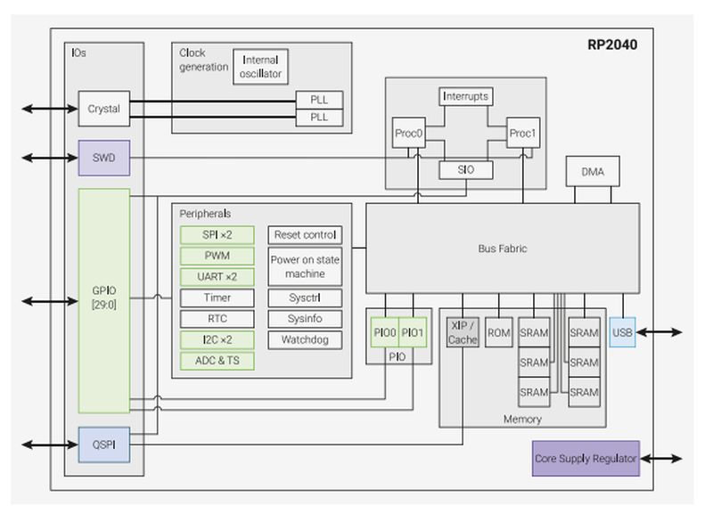
The system overview is as follows;
The pinout of RP2040 is
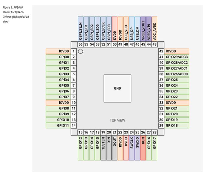
I learnt several words at the previous pages,
now I can see the functions and which port I can choose for certain purpose.
ESP32
This is ESP32 datasheet.
ESP32 has a lot of functions.
- CPU and Memory
- Xtensa single-/dual-core 32 bit LX microprocessors
- 448KB ROM
- 520KB SRAM
- 16KB SRAM in RTC
- QSPI supports multiple flash/SRAM chips
- Peripheral Interface
- 34 programmable GPIOs
- 5 strapping GPIOs
- 6 input-only GPIOs
- 12-bit SAR ADC up to 18 channels
- 2 8-bit DAC
- 10 touch sensors
- 4 SPI interfaces
- 2 I2S interfaces
- 2 I2C interfaces
- 3 UART interfaces
- Ethernet MAC interface with dedicated DMA IEEE 1588 support
- RMT(TX/RX)
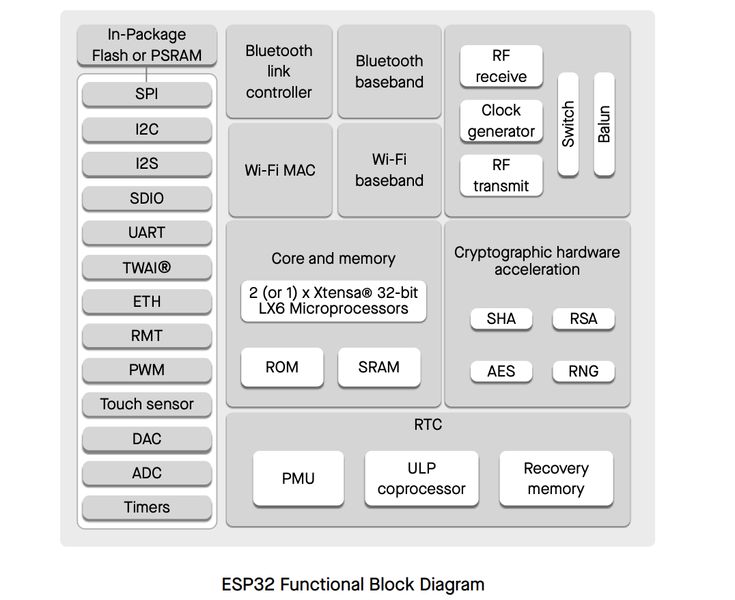
Some of the functions, such as Wi-Fi, DAC and ADC seem to fit my final project. It needs DAC for color chart and Wi-Fi for connect with lights and controller.
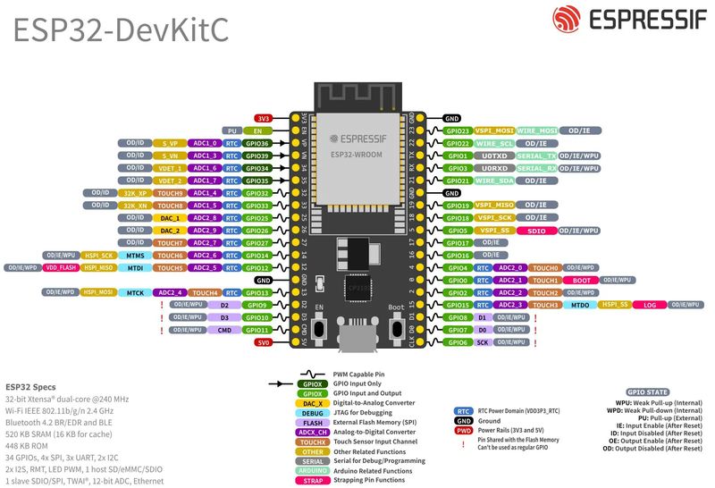
This is a ESP32's functional block diagram.
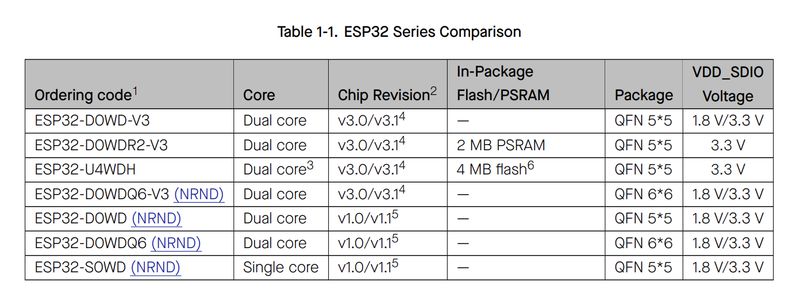
Esp32 provides several series.
These are pinout sheets for ESP32. It has 2 types of pinout layout(depends on the model).
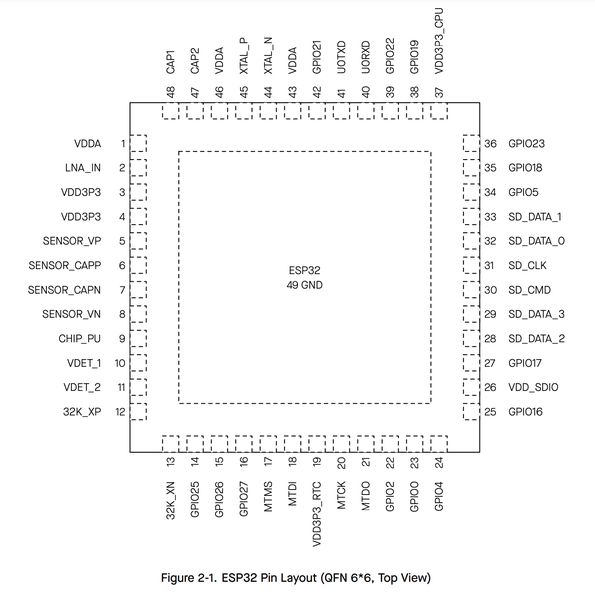
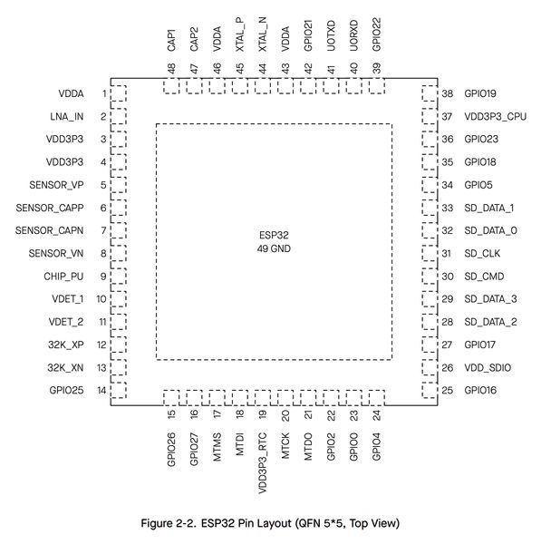
As I want to use the monitor and wi-fi for the final project, I may choose to use ESP32 now.
Write a program to microcontroller
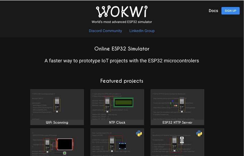
I used "WOKWI" basically as a simulator, Arduino and MicroPython as languages.
- Toolchains
- Arduino
- MicroPython
- controller
- ESP32
- simulator
- Wokwi
- ESP32 : Arduino
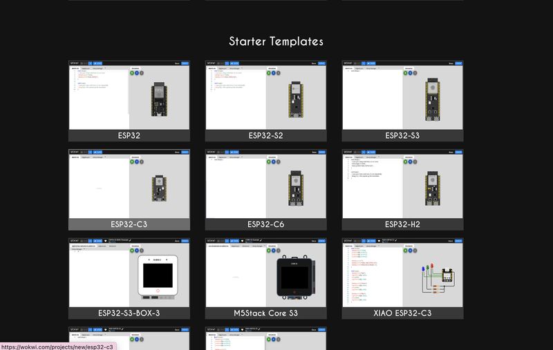
I chose ESP32 → ESP32(starterTemplates)
and I could get the arduino code from my instructor and I put it into WOKWI.
I thought it would work easily, but it didn't.
However, led light is always on and button didn't work at all.
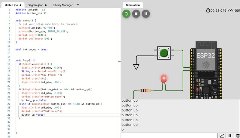
I had no idea why it happened. So I made simpler code with same circuit for understanding the function of led and ESP32.
#define led_pin 25
#define button_pin 33

void setup() {
  pinMode(led_pin, OUTPUT);
  pinMode(button_pin, INPUT_PULLUP);
  Serial.begin(9600);
  Serial.setTimeout(100);
}
 if(digitalRead(button_pin) == LOW){
    Serial.println("button down...");
    digitalWrite(led_pin, HIGH);  //LED ON
  }else if(digitalRead(button_pin) == HIGH){
    Serial.println("button up!");
    digitalWrite(led_pin, LOW);   //LED OFF
  }
This time it worked properly.
Next I made 5 LEDs programming.
This time, when you enter the number from 1 to 5, corresponding light is on
and when you push the button, all lights are off.
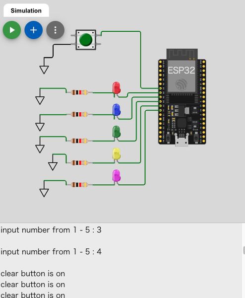
#define button_pin 32
#define led_rouge 33    //red pin
#define led_bleu  25    //blue pin
#define led_vert  26    //green pin
#define led_jaune 27    //yellow pin
#define led_rose  14    //pink pin
#define num_rouge 1
#define num_bleu  2
#define num_vert  3
#define num_jaune 4
#define num_rose  5

#define pin_num 5

bool isDisplay = true;

// functions


void setup() {
  // put your setup code here, to run once:
  pinMode(led_rouge, OUTPUT);
  pinMode(led_bleu, OUTPUT);
  pinMode(led_vert, OUTPUT);
  pinMode(led_jaune, OUTPUT);
  pinMode(led_rose, OUTPUT);
  pinMode(button_pin, INPUT_PULLUP);

  Serial.begin(9600);
  Serial.setTimeout(100);
}

void loop() {

  // put your main code here, to run repeatedly:
     if(digitalRead(button_pin) == LOW){ //Led all off
      Serial.println("clear button is on");
      digitalWrite(led_rouge, LOW);   //LED OFF
      digitalWrite(led_bleu, LOW);   //LED OFF
      digitalWrite(led_vert, LOW);   //LED OFF
      digitalWrite(led_jaune, LOW);   //LED OFF
      digitalWrite(led_rose, LOW);   //LED OFF
    }

   if(isDisplay){
    Serial.print("input number from 1 - 5 : ");
    isDisplay = false;
  }
  if (Serial.available()){
    Serial.write("input number from 1 - 5 : ");
    String s = Serial.readString();
    Serial.println(s);
    int chnm = s.toInt();
    if (chnm < num_rouge || chnm > pin_num){
      Serial.println("Please enter the number from 1 ~ 5");
    }

   else if (digitalRead(button_pin) == HIGH){
      switch(chnm){
        case num_rouge:
          digitalWrite(led_rouge, HIGH);
          break;
        case num_bleu:
          digitalWrite(led_bleu, HIGH);
          break;
        case num_vert:
          digitalWrite(led_vert, HIGH);
          break;
        case num_jaune:
          digitalWrite(led_jaune, HIGH);
          break;
        case num_rose:
          digitalWrite(led_rose, HIGH);
          break;
      }
    }
  }
}
In this program, I also would like to check the "switch" code(same as C language) that I learnt it can be used here from my instructor.
For the final project, I'd like to check the work of RGB LED for color changing.
So I put RGB LED and tried to work it.
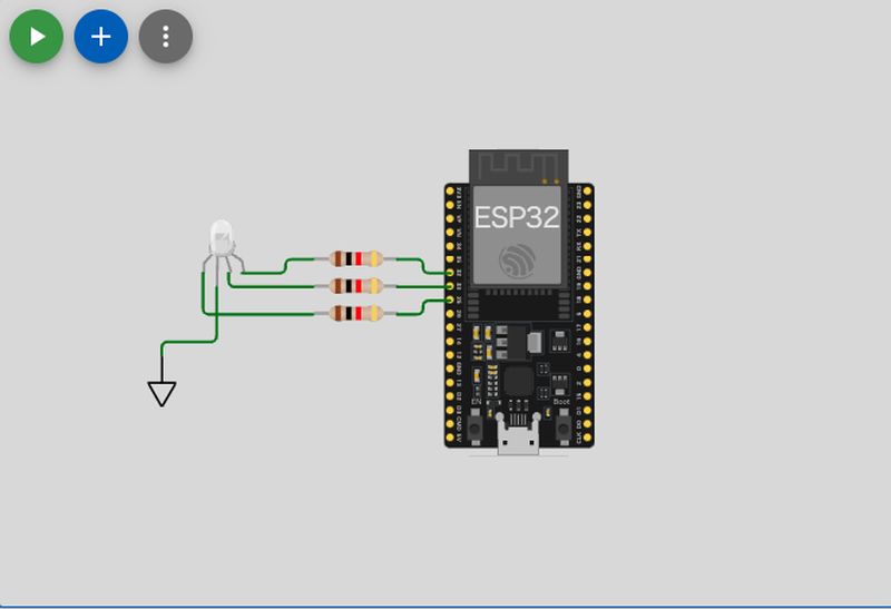
	//LED PIN
	#define rgb_rouge 25
	#define rgb_bleu  32
	#define rgb_vert  33

	void setup() {
	  // put your setup code here, to run once:
	  pinMode(rgb_rouge, OUTPUT);
	  pinMode(rgb_bleu, OUTPUT);
	  pinMode(rgb_vert, OUTPUT);

	  Serial.begin(9600);
	  Serial.setTimeout(100);
	}

	void loop() {
		digitalWrite(rgb_rouge, LOW);
		delay(100);
		digitalWrite(rgb_bleu, LOW);
	 //	delay(100);
		digitalWrite(rgb_vert, HIGH);
	 //	delay(100);

	  delay(10); // this speeds up the simulation
	}
At first, nothing happened. No error. No operation.
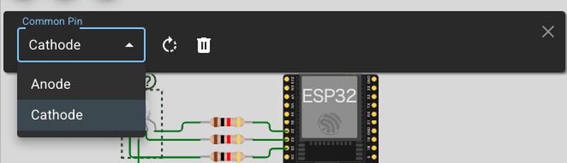
I asked the instructor about it, she told me if I checked the common pin, Anode or Cathode.
I didn't know about it and kept in default(anode).
I changed the common pin to cathode and run the program, this time it worked.
(Of course I put the words "anode" and "cathode" in my words list!)
- ESP32:MicroPython
Next, I tried to make a same program by MicroPython. I got the code from WOKWI and change the pinCode to right number, and check it.
	# MicroPython in ESP32 from the sample code of Pi pico in WOKWI

	from machine  import Pin
	import utime

	red = Pin(25, Pin.OUT)
	green = Pin(33, Pin.OUT)
	blue = Pin(32, Pin.OUT)

	while True:
	  red.value(0)
	  green.value(1)
	  blue.value(1)
	  utime.sleep(1)

	  red.value(1)
	  green.value(0)
	  blue.value(1)
	  utime.sleep(1)

	  red.value(1)
	  green.value(1)
	  blue.value(0)
	  utime.sleep(1)
I used both Arduino and python, it seems Arduino looks easy for me to write until now, as Arduino seems similar to C language for me.
Research
For reading datasheet, I checked many explanation pages in internet.
It's almost all words in electrics are new to me and I needed simple explanation.
I listed several pages in Link section, and many of them are written in Japanese for better understanding for me.
For programming, I researched a lot of page about arduino grammer and how to construct the code. It seems similar to C language for me and I would like to use Arduino further more right now.
What I learned this week
I learnt the words for microcontroller and simulation.
Wokwi helped me a lot for programming and simulating the work of a microcontroller.
I've got a rough idea how to develop my final project concretely
and what controller and programming language are good for it.
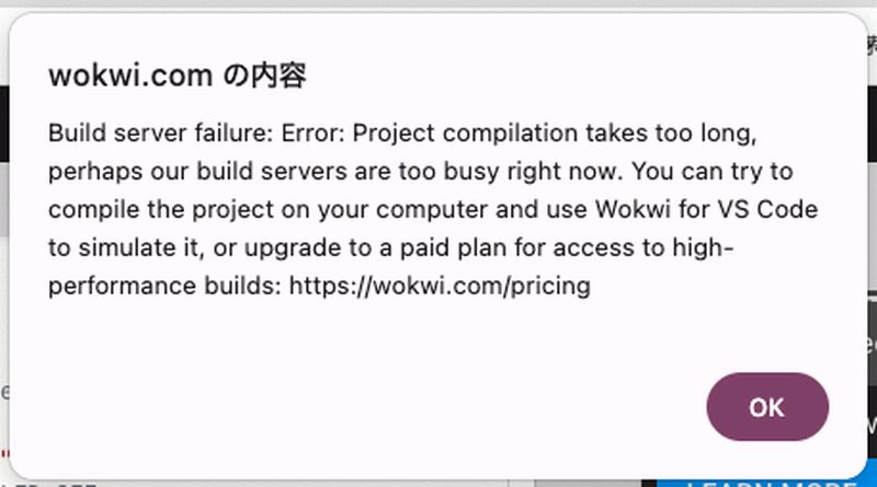
In addtion, I understood this message loved me a lot and appeared me many times.
Useful links
- SPI Interface
- Arduino String->int
- Arduino tutorial
- Arduino tutorial
- Arduino tutorial
- Clock speed
- anode and cathode
- How to start micropython
- MISO / MOSI