
Table of Contents
- Group Assigment
- Compare as many tool options as possible.
- Document your work on the group work page and reflect on your individual page what you learned.
- Individual Assigment
- Write an application for the embedded board that you made. that interfaces a user with an input and/or output device(s)
- Final Project Development
This week my laptop broke down suddenly so it needed to be repaired but the technicians were out of town, so I had to wait.
However if I waited then i would not have been able to update my documentation so I got another laptop.
Since the new laptop didn’t have my previous setup, I had to start by pulling my documentation folder from the repository.
I followed the same steps I had done duringweek 1.
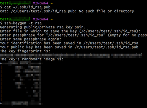
To briefly recap, I generated a new SSH key because this was a different device and the GitLab server didn’t recognize it yet.
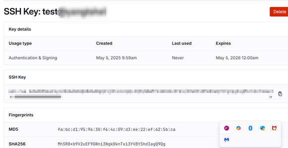
After generating the SSH key, I copied the public key and added it to my GitLab account under SSH Keys. This allowed me to securely connect to my repository using SSH.
Then I used Git to pull my documentation folder and began working on it just like before.
- Opened Git Bash or Command Prompt: On Windows, I opened Git Bash (you can also use Command Prompt or PowerShell).
- Ran the SSH Key Generation Command: I entered the following command:
ssh-keygen -t ed25519 -C "youremail@gmail.com"- -t ed25519: Specifies the type of key (recommended).
- -C "..." : Adds a label (your email) to identify the key.
- Pressed Enter to Accept the Default File Location: I just hit Enter when it asked where to save the key, so it saved to the default path:
C:\Users\YourName\.ssh\id_ed25519 - (Optional) Added a Passphrase: I was asked to enter a passphrase. I could either leave it blank (just press Enter) or add one for extra security.
- Copied the Public Key: Then I copied the key using this command:
or by opening the file in a text editor:cat ~/.ssh/id_ed25519.pubC:\Users\YourName\.ssh\id_ed25519.pub - Pasted the Key into GitLab: Went to GitLab > Preferences > SSH Keys, pasted the key into the field, and saved it.
After generating the SSH key, I copied the public key and added it to my GitLab account under SSH Keys. This allowed me to securely connect to my repository using SSH. Then I used Git to pull my documentation folder and began working on it just like before.
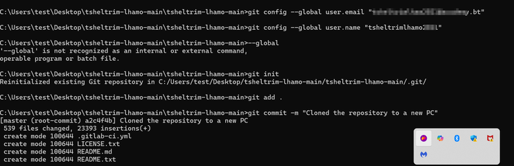
- Set My Global Git Username: I ran the following command to set my global username for Git:
git config --global user.name "tsheltrimlhamo2021" - Set My Global Git Email: I ran this command to set my global email for Git:
git config --global user.email "tsheltrimlham2021@academy.bt" - Initialized the Git Repository: Since the folder wasn't a Git repository yet, I ran the following command to initialize it:
git init - Added Files to the Git Repository: After initializing, I added all the files using:
git add . - Committed the Changes: I committed my changes with a message:
git commit -m "Initial commit" - Linked the Repository to GitLab: I then linked my local repository to the GitLab repository with:
git remote add origin https://gitlab.com/your-username/your-repo.git - Pushed the Changes to GitLab: Finally, I pushed the changes to GitLab with:
git push -u origin master
Group Assignment
For the group assignment, we You can access the group assignment here
Individual Assignment
Tkinter
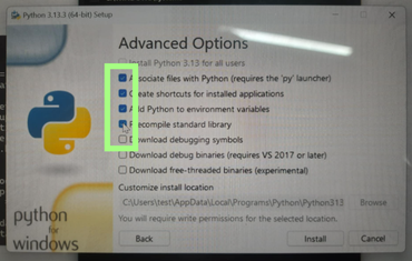
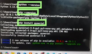
Tkinter is a built-in Python library that facilitates the creation of graphical user interfaces (GUIs) for applications. It provides a variety of widgets such as buttons, text boxes, labels, and menus, allowing developers to design interactive interfaces for their programs. To begin with Tkinter, I first had to download the python application from google. First search python download on google. Then select your preferred options and proceed with the installation. Then to check if python is installed in my laptop I used a command in terminal.
I installed pyserial using pip (with a command like pip install pyserial) so that Python could use the serial module — specifically serial.Serial() — to communicate with hardware like Arduino or other microcontrollers over a serial port (USB, COM, etc.).
By default, Python doesn't include the serial module. The installation step ensures that the pyserial package is added, which gives:
import serial
Without installing it, you'd get an error like ModuleNotFoundError: No module named 'serial'.
Getting Started with Tkinter!
Before coding, I first created a Python file in Visual Studio Code (VSCode). I saved the file with a .py extension and made sure to select Python as the programming language.
Before running a program, I watched a tutorial I understood I needed to install the Python extension in VSCode. After installing it, I wrote a code prompting AI and it worked successfully!
Now that the setup is done, it’s time to get serious with more coding…
Fundamental Tkinter Code I Learned
1. Importing Tkinter
import tkinter as tk2. Creating the Main Window
root = tk.Tk()3. Adding Widgets (Labels, Buttons, etc.)
label = tk.Label(root, text="Hello, Tkinter!")
button = tk.Button(root, text="Click me!")
4. Organizing Widgets Using Geometry Managers
Using pack:
label.pack()
button.pack()
Using grid:
label.grid(row=0, column=0)
button.grid(row=1, column=0)
5. Configuring Widget Properties
label.config(font=("Arial", 12), fg="blue")
button.config(bg="green", command=some_function)
6. Defining Event Handlers
def some_function():
    print("Button clicked!")
7. Running the Main Event Loop
root.mainloop()
Next up, I’ll try designing my own GUI — just before I begin working on the LED switch project!
Bhutanese look to Buddhist astrology for all sorts of reasons from major events such as marriage and partner compatibility.
Akin to the Chinese and Tibetan cultures, Bhutanese have 12 zodiac signs represented by 12 animals.
The twelve animals are believed to be the audience before Buddha passed into Mahaparinirvana, according to an oral tradition. Each animal represents a certain month and year and 12 years is considered one cycle.
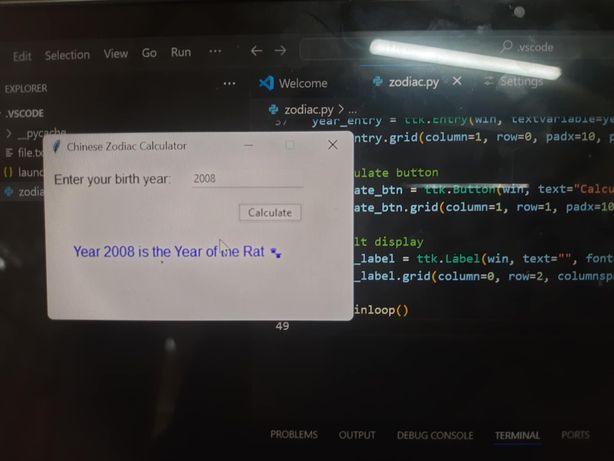
So I designed a GUI to calculate the zodiac based on ones birth year with the help of AI.. The prompt I gave it was "
Generate a Python Tkinter application that calculates the Chinese Zodiac animal for a given birth year. The application should have:
- A main window titled 'Chinese Zodiac Calculator' with a fixed size.
- A label prompting the user to 'Enter your birth year:'.
- An input field for the user to type the year.
- A 'Calculate' button that, when clicked, determines and displays the zodiac animal.
- A label to show the result, including the year and the zodiac animal (e.g., 'Year XXXX is the Year of the [Animal] 🐾').
- Error handling for invalid input (non-numeric or negative years), displaying an appropriate error message (e.g., '❌ Invalid input! Please enter a valid positive year.').
- The zodiac calculation should be based on the standard 12-year cycle, using 2020 as the Year of the Rat as a reference point.
import tkinter as tk
from tkinter import ttk

def chinese_zodiac(year):
    animals = [
        "Rat", "Ox", "Tiger", "Rabbit", "Dragon", "Snake",
        "Horse", "Goat", "Monkey", "Rooster", "Dog", "Pig"
    ]
    base_year = 2020  # Year of the Rat, a known reference
    index = (year - base_year) % 12
    return animals[index]

def calculate_zodiac():
    try:
        birth_year = int(year_var.get())
        if birth_year < 0:
            raise ValueError
        zodiac = chinese_zodiac(birth_year)
        result_label.config(
            text=f"Year {birth_year} is the Year of the {zodiac} 🐾"
        )
    except ValueError:
        result_label.config(
            text="❌ Invalid input! Please enter a valid positive year."
        )

# Create main window
win = tk.Tk()
win.title("Chinese Zodiac Calculator")
win.geometry("350x180")
win.resizable(False, False)

# Year input
ttk.Label(win, text="Enter your birth year:", font=('Arial', 11)).grid(column=0, row=0, padx=10, pady=10, sticky='w')

year_var = tk.StringVar()
year_entry = ttk.Entry(win, textvariable=year_var, width=20)
year_entry.grid(column=1, row=0, padx=10, pady=10)

# Calculate button
calculate_btn = ttk.Button(win, text="Calculate", command=calculate_zodiac)
calculate_btn.grid(column=1, row=1, padx=10, pady=5, sticky='e')

# Result display
result_label = ttk.Label(win, text="", font=('Arial', 12), foreground="blue")
result_label.grid(column=0, row=2, columnspan=2, padx=10, pady=15)

win.mainloop()
-
Function:
chinese_zodiac(year)
This function determines the Chinese Zodiac animal based on a given year. It uses a list of animals and calculates the index using modulo operation:base_year = 2020is used as the reference year for "Rat".index = (year - base_year) % 12gives the corresponding animal.
-
Function:
calculate_zodiac()
This function reads the year entered by the user, validates it, and updates the result label with the corresponding zodiac sign:- Checks if the year is a valid positive number.
- If valid, calls
chinese_zodiacand displays the result. - If invalid, shows an error message.
-
GUI Components (Tkinter)
Tkinter is used to create a simple and user-friendly interface:ttk.Label– Displays instructions and results.ttk.Entry– Text input for the birth year.ttk.Button– Triggers the zodiac calculation.result_label– Displays the output in blue font.
-
Main Window
The main window setup includes:win = tk.Tk()– Initializes the main window.win.title()– Sets the window title.win.geometry()– Sets fixed window size (350x180).win.mainloop()– Starts the GUI event loop.
It first tries to convert your typed year into a number. If you type something that isn't a valid positive number (like "abc" or "-1990"), Python normally gets confused and crashes. But because we've wrapped this part in a try block, if an error happens, the program doesn't crash. Instead, it immediately jumps to the except block, which is like a safety net. The except block then neatly tells you there was "Invalid input!" on the screen, letting you know what went wrong without breaking the application. This makes the program much more user-friendly and robust.
Then I tried controlling my LED with a web interfacec andI generated the code with the help of AI.
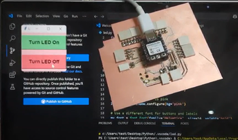
You run the Python Tkinter GUI code here. This code provides buttons for you to press, which send serial commands ('1' or '0') to the Arduino via USB.
import serial
from tkinter import *

def led_on():
    arduino_data.write(b'1')

def led_off():
    arduino_data.write(b'0')

led_control_window = Tk()
led_control_window.title('LED Control')

btn_on = Button(led_control_window, text='Turn LED On', command=led_on)
btn_on.pack(pady=10)

btn_off = Button(led_control_window, text='Turn LED Off', command=led_off)
btn_off.pack(pady=10)

arduino_data = serial.Serial('COM13', 9600)

led_control_window.mainloop()
This is the code in Python which runs on my computer and provides a user interface (GUI) using Tkinter. It allows you to press buttons to send commands to the Arduino, which then controls the LED.
import serial
from tkinter import *
from tkinter import font

def led_on():
arduino_data.write(b'1')

def led_off():
arduino_data.write(b'0')

# Set up the Tkinter window
led_control_window = Tk()
led_control_window.title('LED Control')

# Set background color to pink
led_control_window.configure(bg='pink')

# Use a different font for buttons and labels
my_font = font.Font(family='Helvetica', size=14, weight='bold')

# Create the "Turn LED On" button with a different style
btn_on = Button(led_control_window, text='Turn LED On', command=led_on, font=my_font, bg='lightgreen', fg='black', padx=20, pady=10)
btn_on.pack(pady=10)

# Create the "Turn LED Off" button with a different style
btn_off = Button(led_control_window, text='Turn LED Off', command=led_off, font=my_font, bg='lightcoral', fg='black', padx=20, pady=10)
btn_off.pack(pady=10)

# Initialize the serial connection to Arduino
arduino_data = serial.Serial('COM13', 9600)

# Run the Tkinter event loop
led_control_window.mainloop()
This is the code that I uploaded to my microcontroller.
void setup() {
  pinMode(13, OUTPUT);       // Set the built-in LED pin as output
  Serial.begin(9600);        // Start serial communication at 9600 baud
}

void loop() {
  if (Serial.available() > 0) {      // If data is available to read
    char command = Serial.read();    // Read one byte
    if (command == '1') {
      digitalWrite(13, HIGH);        // Turn LED ON
    }
    else if (command == '0') {
      digitalWrite(13, LOW);         // Turn LED OFF
    }
  }
}
How Your Computer Talks to Your Board-My understanding
The computer and my microcontroller are two people who want to talk, but they don't speak the same language directly. They need a special translator and a dedicated phone line.
-
The "Phone Line" (USB Cable & Serial Port): When you plug your board into your computer with a USB cable, your computer creates a virtual serial port (like COM13). This is like setting up a special, direct "phone line" just for your computer and board to talk on.
-
The "Translator" (pyserial): This is where
pyserialcomes in. It's a Python tool that lets your computer's programs use that "phone line." When your Python code saysserial.Serial('COM13', 9600), it's like picking up the phone, dialingCOM13, and agreeing to speak at a certain speed (called 9600 baud). Both sides must speak at the same speed! -
Sending Messages:
- When you click the "Turn LED On" button on your computer screen, your Python program uses
pyserialto send a tiny message—just the number '1' (as a byte,b'1')—down that "phone line" to your board. - Click "Turn LED Off," and it sends a '0' (
b'0').
- When you click the "Turn LED On" button on your computer screen, your Python program uses
-
Receiving and Acting:
- Meanwhile, your microcontroller board has its own simple program running. This program is constantly "listening" on its end of the "phone line."
- When it receives the '1' message, its program understands this means "turn the LED on!" and it does exactly that by sending power to the LED.
- If it receives '0', it cuts the power, turning the LED off.
Final Project Development
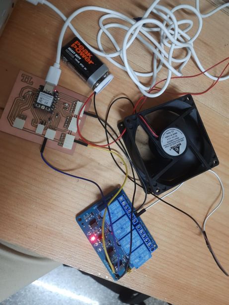
This week, I focused on testing and ensuring that the components functioned correctly. I worked with a 4-channel relay module connected to a DHT sensor. The setup was programmed so that when the DHT sensor detected a temperature above 30°C, it would trigger the relay to turn on a fan. To simulate this condition, I used the warmth of my hands to raise the temperature near the sensor—and it worked perfectly!
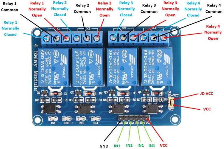
I used the PCB that I made during the Electronics production week , a 4 channel relay, a 9V battery, a 5V dc fan and then some jumper wires.
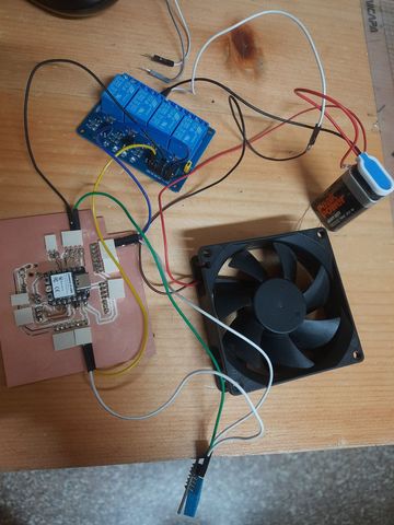
Connecting the relay to the fan and the power supply and the PCB!
Connecting the dht to the already connected relay
The codes that were uploaded kept on giving issues, so I used a multimetre and BINGO- realized there were some short circuits in my board. So then I remade and remilled a generic board this time and when I tested it with it, it worked fine!! Whoo! That debugging and troubleshooting process was very tiresome. I even tried booting my Xiao several times and even changed my code a lot of times. However the problem lied with my board. So I made a generic board, milled and soldered it and then Woohoo! it worked.
This video showcases the successful test of my program in action. Initially, the fan remained off as the temperature was below 30°C. However, after applying heat to the DHT sensor using my hands—triggering heat transfer—the sensor detected a rise in temperature above 30°C. In response, it sent signals to the Xiao ESP32-C3, which then activated the relay, turning the fan on.
#include "DHT.h"

// Pin definitions
#define DHTPIN 2             // GPIO2 on XIAO ESP32-C3
#define DHTTYPE DHT22        // Use DHT11 if that's your sensor
#define RELAY_PIN 3          // GPIO3 to control the relay

#define TEMP_THRESHOLD 30.0  // Temperature threshold in °C

DHT dht(DHTPIN, DHTTYPE);

void setup() {
  Serial.begin(115200);
  dht.begin();

  pinMode(RELAY_PIN, OUTPUT);
  digitalWrite(RELAY_PIN, LOW);  // Ensure fan is off at start
}

void loop() {
  delay(2000); // DHT sensor requires at least 2 sec delay

  float temperature = dht.readTemperature();

  // Check if reading failed
  if (isnan(temperature)) {
    Serial.println("Failed to read from DHT sensor!");
    return;
  }

  Serial.print("Temperature: ");
  Serial.print(temperature);
  Serial.println(" °C");

  if (temperature > TEMP_THRESHOLD) {
    digitalWrite(RELAY_PIN, HIGH); // Turn fan ON
    Serial.println("Fan ON");
  } else {
    digitalWrite(RELAY_PIN, LOW);  // Turn fan OFF
    Serial.println("Fan OFF");
  }
}
Files
You can access the files here
Generic Board's rml and kicads original file too