Assignments
This week we learned about electronics production and it was amazing. The way you had to find all of those tiny components[resistors and led] and pin sockets and had to solder it to your board. How you had to be extra careful while zeroing the x,y and z axis while using the SRM machine and how you had to make sure that the endmill doesn't break because it is expensive! It was also fun learning how you connect a USB cable to the Xiao Esp32 c3 as a power supply and as a way to upload your code from Arduino Ide. It was crazy how many different libraries were there for it too! Then there comes the debugging! really hard to find mistakes cause even a really small error stops the entire board from functioning! Anyways this time I thoroughly enjoyed everything
Table of Contents
- Group Assigment
- Individual Assignment
- Final Project Development
- Characterize the design rules for your in-house PCB production process: document feeds, speeds, plunge rate, depth of cut (traces and outline) and tooling.
- Document the workflow for sending a PCB to a boardhouse
- Document your work to the group work page and reflect on your individual page what you learned
- End mills: Metal pieces that are used to remove material.
- Sacrificial Layer: A layer below the copper plate that is slowly removed when the end mills go beyond the designated cutting area.
- Zeroing Adjusting your end mill to be positioned at t=your set origin.
- Clean and shiny soldering iron tip
- 300℃ - 350℃ temperature
- Flux on the pads before dropping solder on it
- Heat both the pad and component to get them to rise to the same temperature, then solder will stick to both
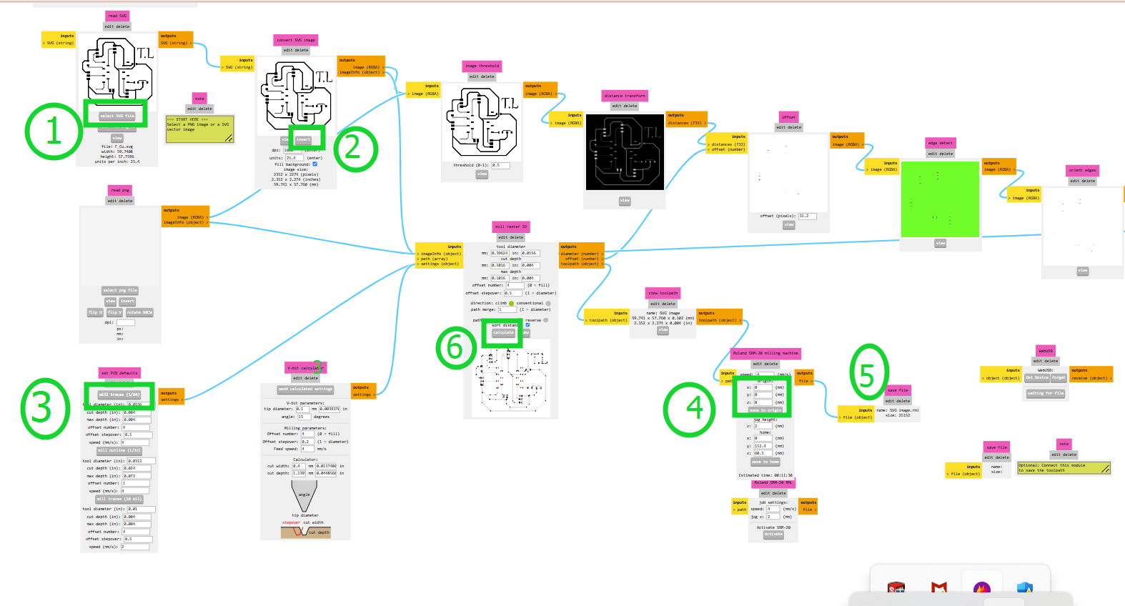
- Insert an SVG or PNG file (we will use an SVG file).
- Invert the image.
- Inversion is necessary because the software interprets black areas as regions to **preserve** and white areas as regions to **mill away**.
- By inverting, the traces remain intact while the surrounding copper is removed.
- Select "Mill traces by 1/64 inch" since we are using a 1/64-inch endmill for copper cutting.
The same procedure applies for edge cuts, except in STEP 3, where you must select "Mill with 1/32 endmill" as we will be using that for edge cutting. - Set all axes (X, Y, and Z) to 0.
- Delete two unnecessary items (which are on/off elements and you can delete them by clicking on "edit delete"), then right-click and select Add Module.
- Go to Files, click Save, and connect it to the Outputs file.
- Press "Calculate", and your RML file is ready to print!
- Trace milling: 0.4 mm Flat End Mill (1/64 inch)
- Outline cutting: 0.8 mm Flat End Mill (1/32 inch)
- Start with tracing, so use the 1/64 inch endmill.
- Set the part you want to cut as (0,0), not the machine’s origin.
- In the "Set Origin Point" section, press X/Y and confirm that both turn to 0.
- Bring the tip of the endmill as close as possible to the board using the screen controls.
- Gently lower the endmill onto the board, then close the collet.
- Lightly pressing it onto the board improves cutting accuracy.
- In the "Set Origin Point" section, press Z and confirm it turns to 0.
- Press the Cut button and select the file to mill.
- Delete any previously selected files before choosing your .nc or .gcode file.
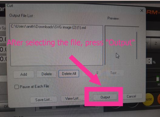
- Press Output to start the milling process.
Roadmap

Group Assignment
Weekly Tasks
Design Rules
PCB Workflow
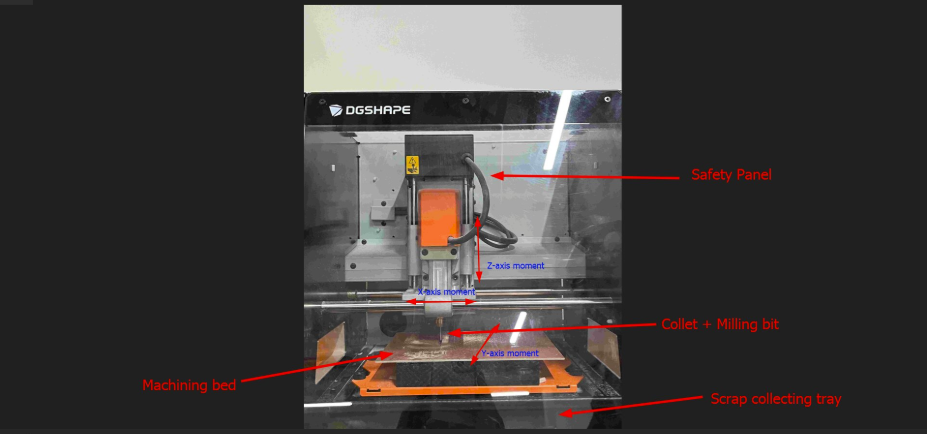
Our milling machine is the Monofab SRM-20 Milling Machine. Here’s a labelled picture that gives you a basic idea of how the machine works. I got this picture from my friend Damzang. You can access the group assigment page here
Individual Assignment
Make and test a microcontroller development board that you designed
Quentorres Board customization
This week, we had to make and test a microcontroller development board that we designed, but[careless me] did not read the assignment properly and instead of using the board that I designed from scratch, I used the Quentorres Board. It was originally created by Quentin Bolsée and later redesigned by Adrián Torres.
The Quentorres is basically a programmer that helps with microcontroller development, especially for AVR Series 1 & 2 and ARM (SAMDino) microcontrollers. It even has a button and an LED, which makes it easier to test and experiment with.
However while I was generating the toolpath for the design, my loca instructor stopped me and asked what I was doing and I excitedly explained to him what I did. Then he shook his head and explained to me what the actual assignment was. From now onwards I should be extra careful while doing the assignments! Well, this is what I did till I was brought back to the trangic realization of my mistake!
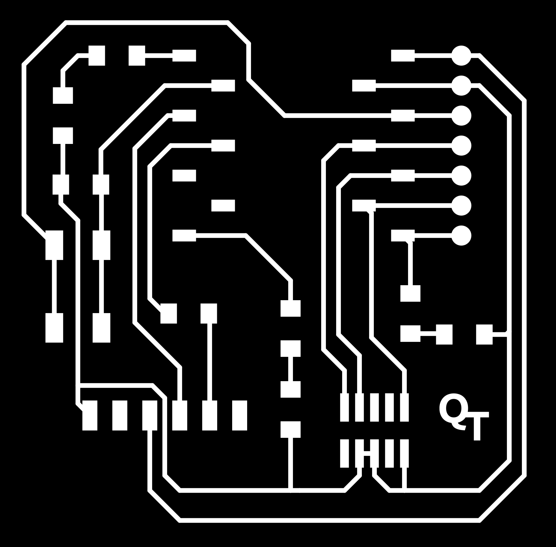
Firstly, I downloaded the png files here
These images are arranged as trace, interiror and drill!


Customizing
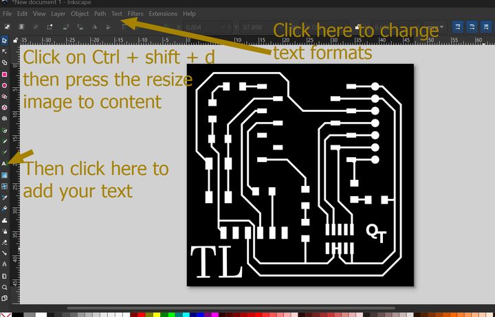
Then to customize the board, I added my initials using inkscape
The Actual Assignment
I decided to mill the final project board that I designed last week. And I continued to work on it. I generated its toolpath thats given in last weeks documentation. YOu can access it here I mainly focussed on milling and practicing soldering and not breaking the end mill because our local instructor would be very mad as that tiny piece of thing is very expensive!
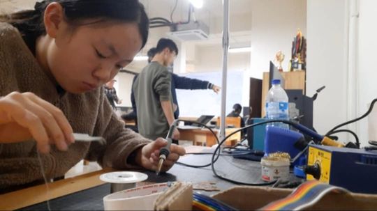
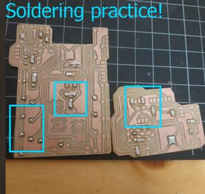
To proceed with the milling, firstly we had to do the zeroing, after which we cut the traces, then the edge cuts too! This is a picture of me practicing soldering on some used boards and putting capicitors in their positions(just practicing and I learned that I wasn't born with a natural talent for it. But the right practice makes perfect-so lets work hard.)
At first, my soldering attempts resulted in large, half-spherical blobs and then I sent the pictures to Rico san who gave me very good advices.
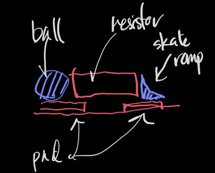
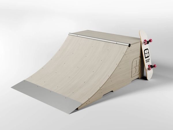
He told me that while soldering, it shouldnt look like a ball but instead should look like a skate ramp. He also gave me some really useful tips with which I gradually improved my ungifted soldering skills.
Soldering Tips
P.s. I had to redesign my board as 1 of my sensors for the final project needed a 3x1 pin socket so I remodified the design and converted it into an rml file and then followed the same procedures as given above.
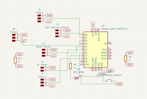
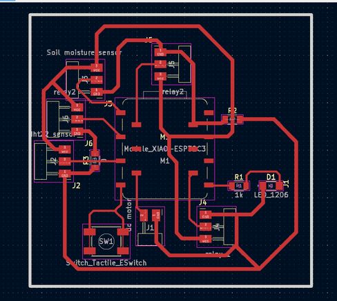
Mods CE
After that, we have to convert those PNG files to RML files. Mods CE is a website that allows users to create toolpaths, control CNC machines, generate G-code, and process images for laser cutting, milling, and 3D printing. These are the steps that I followed to prep my files for milling.
You can access the details to generate a toolpath here
First of all, go to MIT MODS. Then right click -> Programs -> Open Program -> Roland (SRM-20 mill 2D PCB)-> Select svg
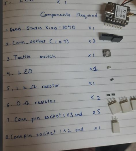
NOTE: I mistakenly wrote Seed Studio instead of my microncontroller's actual name which is Xiao Esp32 c3
Roland SRM-20 Milling Guide

I borrowed this image fromDamzangs website as it offers a comprehensive labelled diagram of the machine here at our lab
For this week's individual assignment, I milled a custom microcontroller development board. The PCB material I used was FR-1. It's a common and affordable material that works well for prototyping.
To secure the FR-1 board to the Roland SRM-20 milling machine, I used double-sided tape. I applied several strips of the tape to the back of the blank PCB, ensuring even coverage. Then, I carefully positioned it on the sacrificial layer of the machine bed and pressed down firmly to ensure it was well-adhered and wouldn't move during the milling process.
The milling process involved two stages, requiring a change of the end mill. First, I milled the traces using a fine 1/64 inch (0.4 mm) flat end mill. Once the traces were complete, I needed to cut out the outline of the board. To do this, I paused the machine and proceeded to change the milling bit.
The process for changing the bit was as follows: I first loosened the collet that held the 1/64 inch end mill. After carefully removing it, I inserted the larger 1/32 inch (0.8 mm) flat end mill into the collet and tightened it securely. It's crucial to ensure the new bit is firmly in place to prevent any slippage during the cutting process. Importantly, I did not reset the X and Y origin points, as these were already accurately set for the trace milling. I only needed to carefully re-zero the Z axis to ensure the new, larger end mill was at the correct starting height relative to the PCB surface.
1. Set the Endmill
- Tools and Bits To Use:
2. Set X/Y Origin
3. Set Z Origin
In VPanel, click "Set Origin Point" → "Home" to move the spindle to the home position. Then use the X, Y, Z arrow buttons to move the spindle to the desired milling start point manually.
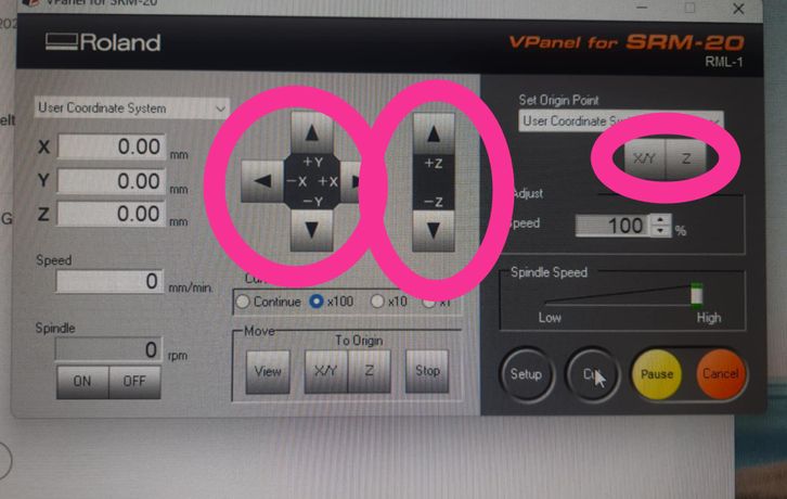
4. Start Milling
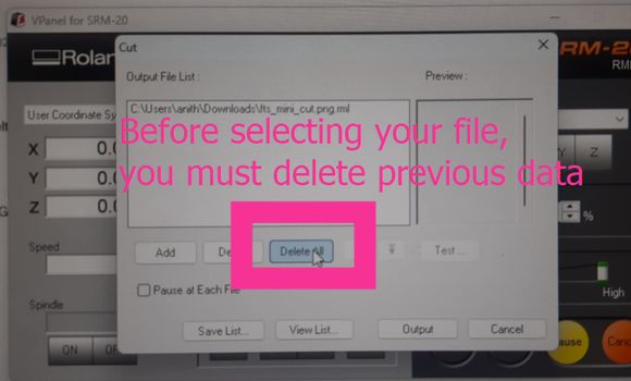
Then click "Output" to preview the toolpath.
After the milling is done, small chips or fine dust accumulate around the work area. So we have an awesome vacuum to clear the debris.
To cut the edge cuts, we have to change mill to 1/32 bit and press on the x/y and the do the zeroing for z-axis. NOTE: Do not set origin the x/y coordinates again!
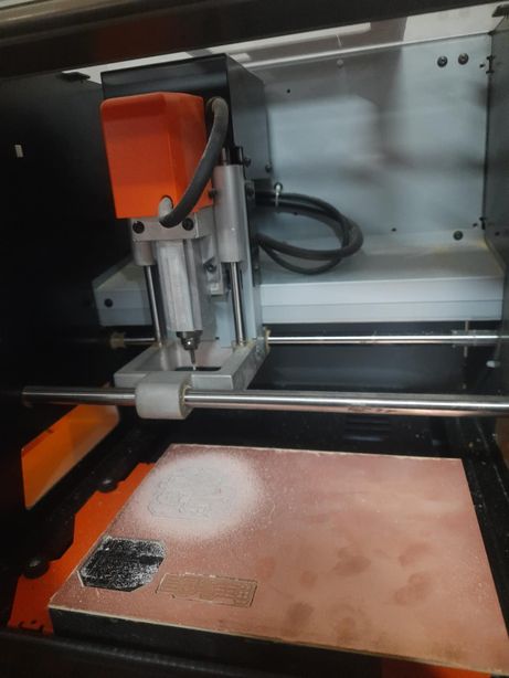

After that I took it out carefully with a flat spatula.While it's indeed a good practice to clean the PCB with steel wool after milling to remove any burrs or oxidation, I did not personally perform this step after milling my board this week. I just vacuumed it.


Yipee! After another careful examination and application, I was able to do it!! And then I started soldering it with the components shared earlier! The practice of 2 hours that I did earlier helped a lot!! Then I did the continuity test with my local isntructor.
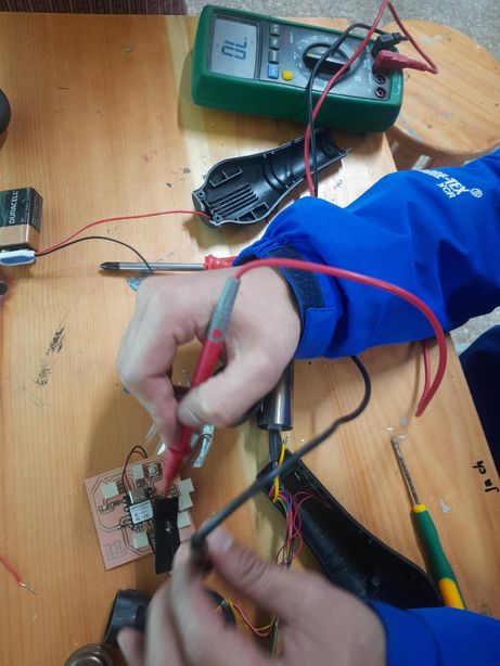
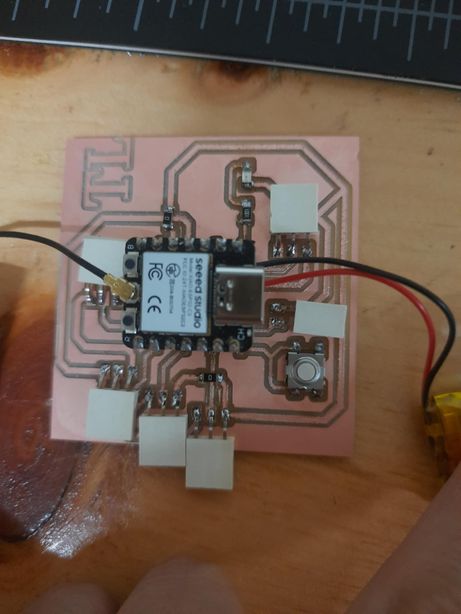
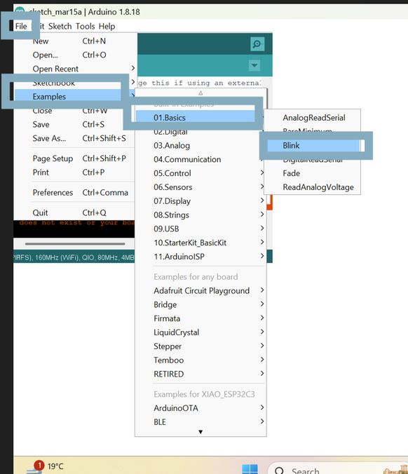
Then I uploaded a blink code to my PCB and it did not work at first but it was because I placed the Xiao in the opposite manner as it was supposed to be placed! Silly me! But after then correction it was very smooth!
To compress this video firstly I went to command prompt and then changed my directory with the following command: cd C:\Users\tshel\OneDrive\Pictures Then I removed the audio and compressed it with the command: ffmpeg -i vid.mp4 -vcodec libx264 -crf 35 -preset veryslow -an -b:v 500k compressed_vid.mp4 and the video was compressed from 1.4 mb to 116 kb! Fantastic right?
                                This is the in built example code for blink in arduino ide
                                /*
  Blink

  Turns an LED on for one second, then off for one second, repeatedly.

  Most Arduinos have an on-board LED you can control. On the UNO, MEGA and ZERO
  it is attached to digital pin 13, on MKR1000 on pin 6. LED_BUILTIN is set to
  the correct LED pin independent of which board is used.
  If you want to know what pin the on-board LED is connected to on your Arduino
  model, check the Technical Specs of your board at:
  https://www.arduino.cc/en/Main/Products

  modified 8 May 2014
  by Scott Fitzgerald
  modified 2 Sep 2016
  by Arturo Guadalupi
  modified 8 Sep 2016
  by Colby Newman

  This example code is in the public domain.

  https://www.arduino.cc/en/Tutorial/BuiltInExamples/Blink
*/

// the setup function runs once when you press reset or power the board
void setup() {
  // initialize digital pin LED_BUILTIN as an output.
  pinMode(LED_BUILTIN, OUTPUT);
}

// the loop function runs over and over again forever
void loop() {
  digitalWrite(LED_BUILTIN, HIGH);   // turn the LED on (HIGH is the voltage level)
  delay(1000);                       // wait for a second
  digitalWrite(LED_BUILTIN, LOW);    // turn the LED off by making the voltage LOW
  delay(1000);                       // wait for a second
}
While not explicitly required for this week's assignment, reflecting on the process makes me realize the importance of running a Design Rule Check (DRC) in the future, especially now that I have a better understanding of the limitations of the SRM-20 machine. It's a step I'll definitely prioritize in subsequent electronics design projects to avoid potential milling issues.
A Design Rule Check (DRC) is an automated process in PCB design software that verifies if your layout meets predefined rules based on manufacturing limits, industry standards, and design needs. It's crucial because it ensures manufacturability, detects errors early, improves reliability and performance, reduces costs and iterations, optimizes board space, and guarantees standards compliance. By catching issues like too-close traces or incorrect via sizes before production, DRC saves time and money, leading to better and more reliable circuit boards. Understanding machine limitations, like those of the Roland SRM-20, makes DRC even more important for successful fabrication.
Files
You can access the files here
Quentorres board customization
Final Project Board
