Electronics Production
- Characterize the design rules for your in-house PCB production process: document feeds, speeds, plunge rate, depth of cut (traces and outline) and tooling.
- Document the workflow for sending a PCB to a boardhouse
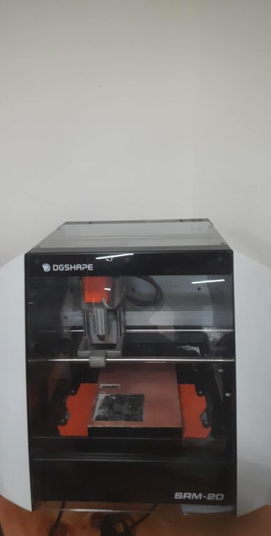
The Monofab SRM-20 is a compact desktop milling machine designed for precision prototyping and small-scale manufacturing. It allows users to mill a variety of materials but we will be using it with modeling wax and PCB boards for our assignments. You can learn more about it here
SRM-20 Desktop Milling Machine Specifications
Understanding the specifications of the SRM-20 is very important for ensuring proper usage, safety, and efficiency. The specifications inform us about the types of materials the machine can cut, the maximum size of the workpieces it can handle, and how precise and accurate the milling process will be. Details such as spindle speed, mechanical resolution, and cutting area help users plan their projects effectively and choose the right settings and tools. Additionally, knowing the power requirements, interface options, and environmental conditions allows for a proper setup of the machine in the workspace. We learned about it here
| Model | SRM-20 |
|---|---|
| Cuttable Material | Modelling Wax, Chemical Wood, Foam, Acrylic, Poly acetate, ABS, PC board |
| X, Y, and Z Operation Strokes | 203.2 (X) x 152.4 (Y) x 60.5 (Z) mm |
| Workpiece Table Size | 232.2 (X) x 156.6 (Y) mm |
| Distance From Collet Tip to Table | Max. 130.75 mm (5.15 in) |
| Loadable Workpiece Weight | 2 kg (4.4 lb) |
| X-, Y-, and Z-Axis Drive System | Stepping Motor |
| Operating Speed | 6 - 1800 mm/min (0.24 - 70.87 inch/min) |
| Software Resolution | 0.01 mm/step (RML-1), 0.001 mm/step (NC code) 0.000039 inches/step (RML-1 or NC code) |
| Mechanical Resolution | 0.000998594 mm/step (0.0000393 inches/step) |
| Spindle Motor | DC motor Type 380 |
| Spindle Rotation Speed | Adjustable 3000 - 7000 rpm |
| Cutting Tool Chuck | Collet Method |
| Interface | USB |
| Control Command Sets | RML-1, NC code |
| Power Requirements | Machine: DC 24V, 2.5A AC Adapter: AC 100-240 V ±10%, 50/60 Hz |
| Power Consumption | Approx. 50 W |
| Operating Noise | During operation: ≤ 65 dB (A) During standby: ≤ 45 dB (A) |
| External Dimensions | 451.0 (W) x 426.6 (D) x 426.2 (H) mm |
| Weight | 19.6 kg (43.2 lb) |
| Installation Environment | Temperature: 5 to 40°C (41 to 104 °F) Humidity: 35 to 80% (no condensation) |
| Included Items |
USB cable, AC adapter, Power cable, Cutting tool, Collet, Set screw, Spanners (7, 10 mm), Hexagonal wrenches (2, 3 mm), Positioning pins, Double-sided tape, Start-up guidance card |
Characterizing Design Rules
We used Prof. Neils characterized files to define the rules.

Then convert the png files into svg using Inkscape.
NOTE: Dont forget to resize the background to the image because later on it will look very small in MODS CE which
wasted 15 minutes of our time wondering what went wrong.
Then you convert the file into rml files using MIT MODS
and you can learn more about it in the electronics designing group assignment that we did
First of all, go to MIT MODS. Then right click -> Programs -> Open Program -> Roland (SRM-20 mill 2D PCB)-> Select svg
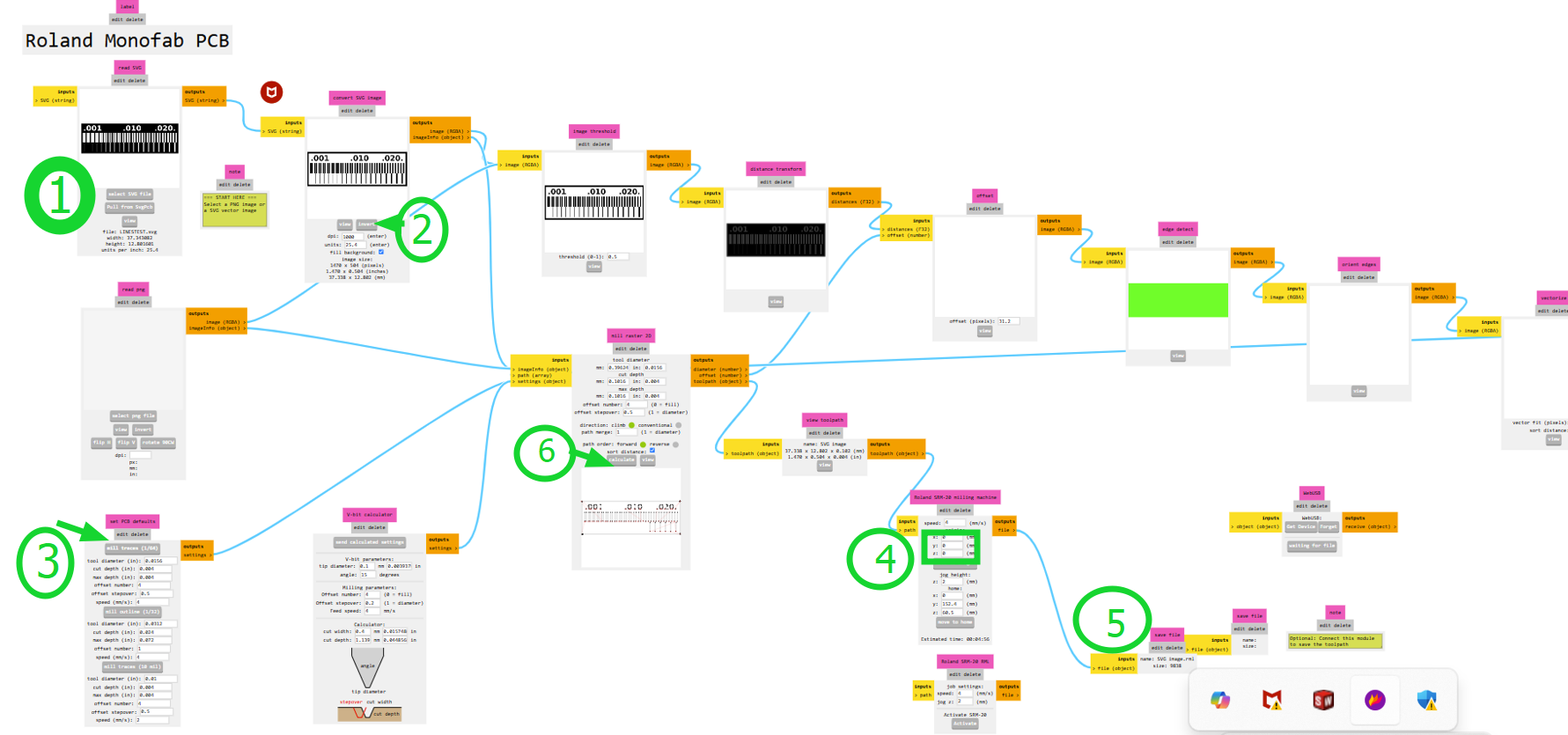
- Insert an SVG or PNG file (we will use an SVG file).
- Invert the image.
- Inversion is necessary because the software interprets black areas as regions to **preserve** and white areas as regions to **mill away**.
- By inverting, the traces remain intact while the surrounding copper is removed.
- Select "Mill traces by 1/64 inch" since we are using a 1/64-inch endmill for copper cutting.
- Set all axes (X, Y, and Z) to 0.
- Delete two unnecessary items (which are on/off elements and you can delete them by clicking on "edit delete"), then right-click and select Add Module.
- Go to Files, click Save, and connect it to the Outputs file.
- Press "Calculate", and your RML file is ready to print!
The same procedure applies for edge cuts, except in STEP 3, where you must select "Mill with 1/32 endmill" as we will be using that for edge cutting.
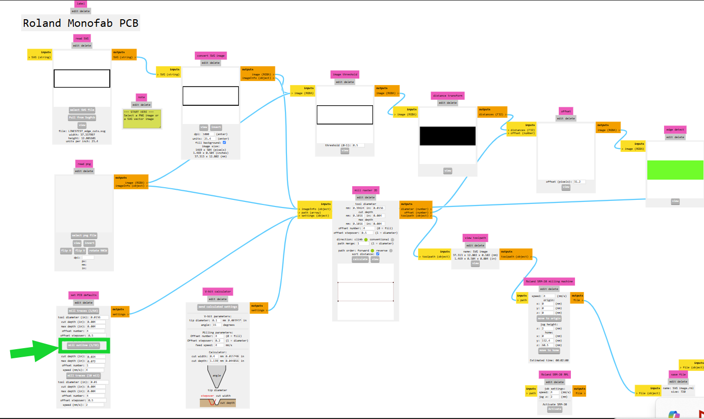
Milling Files
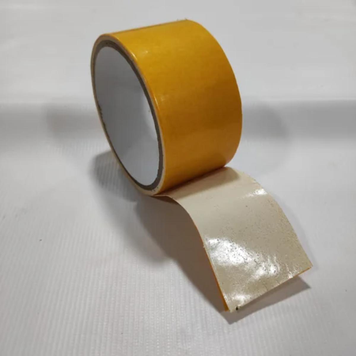
We used double sided tape to stick the board! Image source.
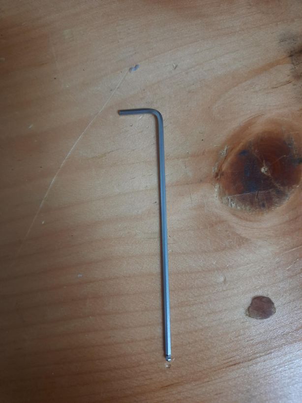
- The SRM-20 uses collets to hold the cutting tool in place, and an Allen key is needed to tighten or loosen the collet screw when swapping out different end mills.
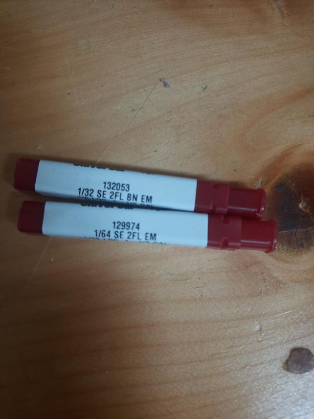
We use 2 endmills while fabricating a pcb. The 1/32-inch end mill is used for cutting the outline of a PCB , creating larger features, and performing general milling tasks. The 1/64-inch end mill is designed for milling thin copper traces on a PCB.
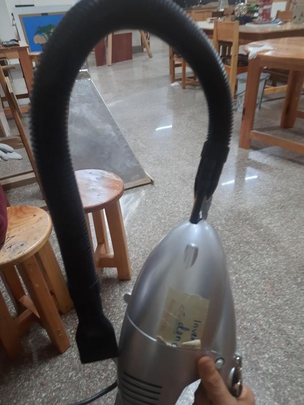
Using a vacuum cleaner helps remove these particles, ensuring a clean and safe working environment is very important to so, this is a picture of the vacuum cleaner we have at out lab.
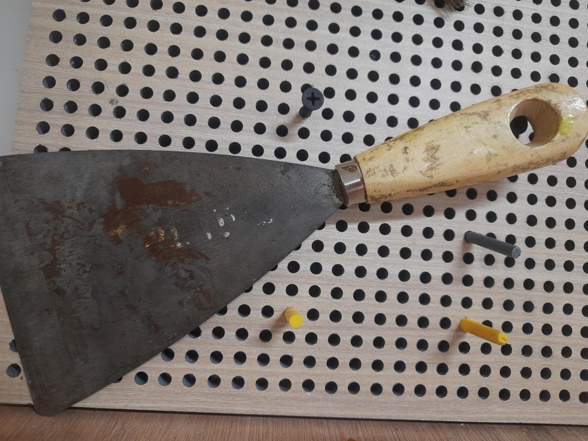
Once a PCB has been cut, removing it properly is crucial to avoid damaging delicate traces or components and that is where the spatula comes in. This is an image of the spatula at our lab.
Result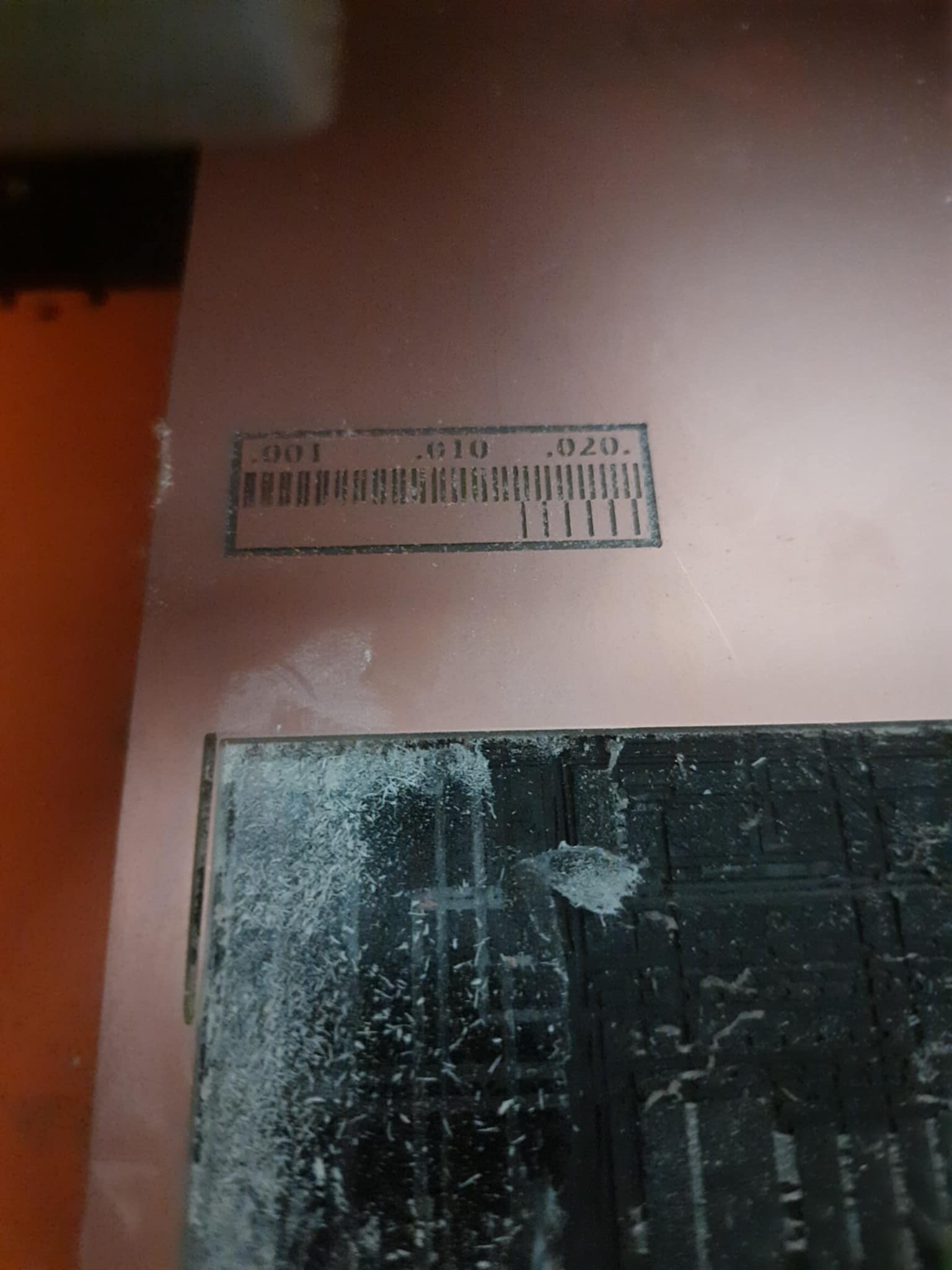
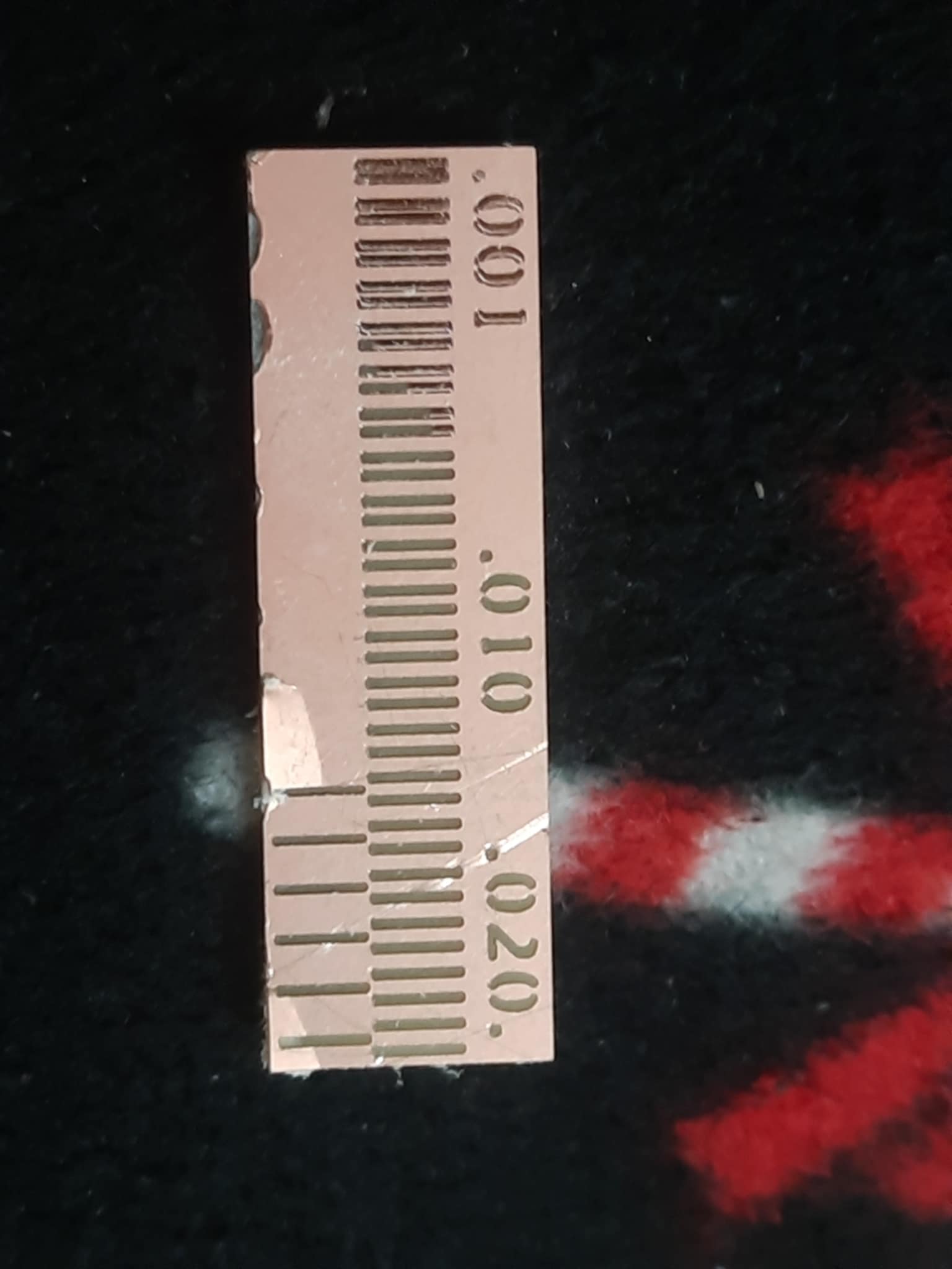
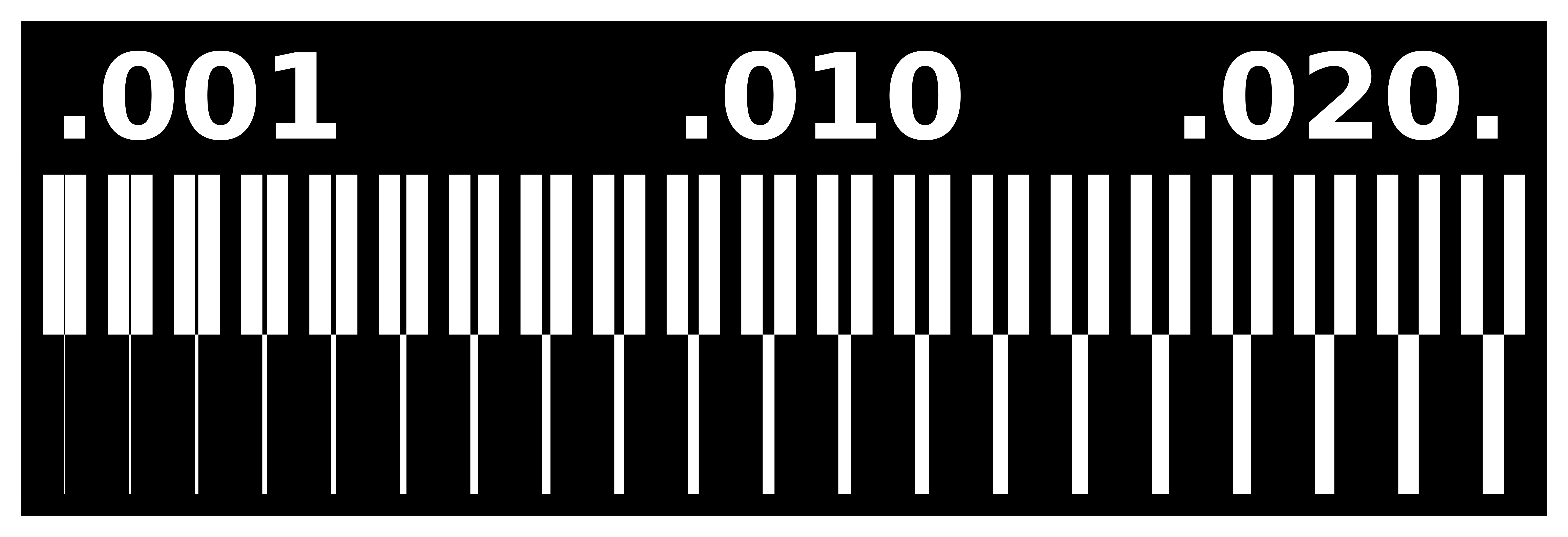
The 1st outcome was not as expected due to bad block levelling. So we levelled our block properly and did it again.
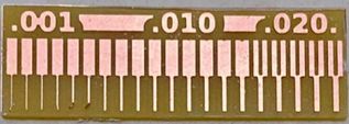
We concluded that only the 0.020 range shows proper visibility of the trace width and spacing. This is due to the fact that the only range larger than 1/64" (0.015) is 0.02. We must therefore stick to this range while designing our circuit boards in the future.