Assignments
This week we had our reviews(exams) so I wasn't able to explore and work on the output devices as much as I would have liked. However I did complete all of my assignments but couldn't progress much with my final project development. In a nutshell, this week was amazing. I explored LCD, OLED and servo motors and the experience was wonderful. However I had actually started debugging and troubleshooting my boards and the codes this week and it was tiresome at some point and frustrating at others. However I pulled through, a survivor like no other!
Table of Contents
- Group Assignment
- Measure the power consumption of an output device.
- Document your work on the group work page and reflect on your individual page what you learned.
- Individual Assignment
- Add an output device to a microcontroller board you've designed and program it to do something.
- Final Project Development
- We collected the things we needed:
- A multimeter
- The device we wanted to test
- A power source
- Wires
- We made sure to stay safe by wearing safety goggles.
- We checked the multimeter to make sure it was working right.
- We connected the power source to the input of the multimeter.
- Then we connected the output of the multimeter to the device.
- We made sure all the wires were connected tightly.
- We turned on the device and waited for it to work normally.
- We looked at the multimeter to read:
- Voltage (V)
- Current (I)
- We wrote down the numbers.
- We used this simple formula:
Power (W) = Voltage (V) × Current (I) - Then we compared our results to the device’s normal values to see if it was working as expected.
- VCC-VCC
- GND-GND
- SCL-D5(Designated connection for SCL in Xiao esp32 c3)
- SDA-D4(Designated connection for SCL in Xiao esp32 c3)
Roadmap
Group Assignment
This week, our group learned how to measure the power use of a device. This is helpful when making our own boards, to check if everything works well or if something needs fixing. You can find more about our group assignment here
Power Consumption
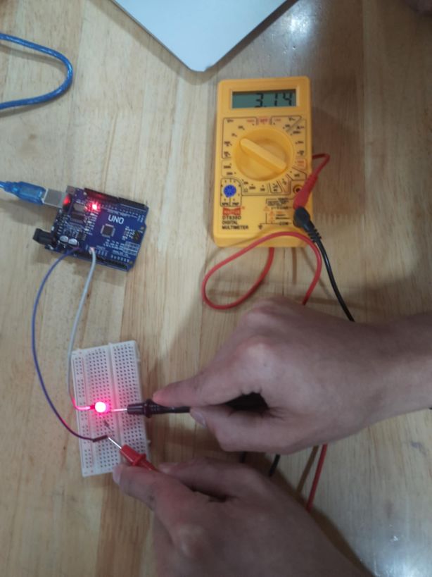
We used a multimeter to measure how much power the device uses. Here's what we did:
1. Getting Ready
2. Making the Connections
3. Turning On and Measuring
4. Calculating Power
This activity helped us understand how much power a device uses and why it’s important when making or fixing our own boards.
Reflection
Measuring the power use of a device turned out to be a really fun and interesting experience. I learned a lot, and there were a few “wow” moments too. Our team did a good job getting everything ready. We made sure we had all the tools we needed, and we stayed safe with our safety goggles on. Connecting the power source to the multimeter and then to the device felt kind of cool—like we were on a tech mission 😭. One of the most important things I learned was the difference between measuring voltage and current. Voltage is measured in parallel, meaning you connect the multimeter across two points of a circuit to see the potential difference. Current, however, must be measured in series, which means the multimeter becomes part of the circuit path, so that all the current flows through it. This is because voltage is like measuring the "pressure" between two points, while current is like measuring the "flow" passing through a single point. Understanding this helped us set up the experiment correctly and safely. Seeing the power meter light up was super satisfying. And honestly, doing the calculations afterward was more fun than I expected. We’ve learned before that Power = Voltage × Current, but learning it through this hands-on experience made it way more fun and meaningful. Doing the calculations after seeing the real numbers felt amazing and way better than just reading it in a book.
Individual Assignment
Before getting into the Arduino programming world, we must know some basic terms such as: #include is used to add libraries, which are collections of pre-written code that provide additional functionality, such as controlling displays, sensors, or motors. The void setup() function is a special block that runs once at the beginning of the program; it is used to initialize settings like pin modes or start communication protocols. The void loop() function runs repeatedly after setup() and contains the main logic that the Arduino executes continuously. A function call is when a specific function is invoked to perform a task, such as turning on an LED, printing to a screen, or reading a sensor. The delay() function pauses the program for a specified number of milliseconds, which is useful for creating time gaps between actions or slowing down repetitive tasks. These elements together form the basic structure and flow of most Arduino sketches.
With Arduino
LCD
We had to add an output device to a microcontroller board I've designed and program it to do something. For this I decided to try out simple output devices like LCD 16x2 as it was time to explore.
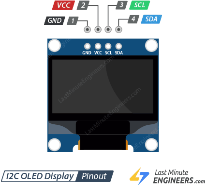
We will be using an I2C module which is basically a serial communication protocol that allows microcontrollers and peripheral devices to communicate over a two-wire bus, using SDA (Serial Data) and SCL (Serial Clock) lines, enabling efficient data exchange for short-distance applications. An I2C LCD interface module simplifies connecting and controlling LCD displays using the I2C protocol, reducing the number of required GPIO pins on microcontrollers and simplifying wiring. Image source.
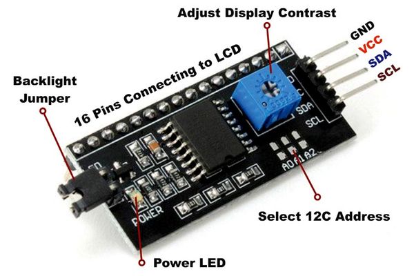
Connections: Very important to check out your micro controllers pinouts. I checked Xiao Eso32 c3's pinouts
p.s. I assumed SCL wasn't requried because it was clock but turns out it was very important. Took me about 2 hours to figure out this problem later on!
Next, I had to download an external library for the LCD I2C module, which is available
here or from the Arduino software itself.
The Arduino IDE includes a built-in library for LCDs, but it does not support the I2C module by default. Therefore, I had to install an additional library for LCD I2C.
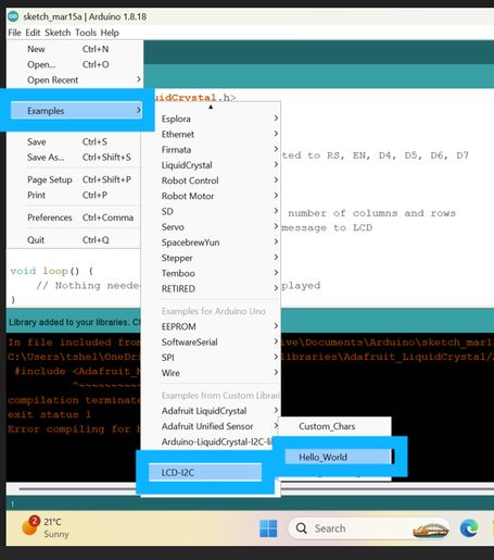
If you are using the library from the provided link, it comes as a ZIP file after downloading. 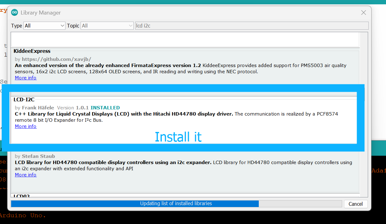
To install it, open the Arduino IDE, go to Sketch > Include Library > Add .ZIP Library, and select the downloaded file.
After having this library installed your software, go to files > examples and you will see that the library comes with attached examples. So I first chose the hello board example and it ...did not work!!!
#include <LCD-I2C.h>
#include <Wire.h>

LCD_I2C lcd(0x27, 16, 2); // Default address of most PCF8574 modules, change according

void setup() {
    Wire.begin();
    lcd.begin(&Wire);
    lcd.display();
    lcd.backlight();
}

void loop()
{
    lcd.print("     Hello"); // You can make spaces using well... spaces
    lcd.setCursor(5, 1); // Or setting the cursor in the desired position.
    lcd.print("World!");
    delay(500);

    // Flashing the backlight
    for (int i = 0; i < 5; ++i)
    {
        lcd.backlight();
        delay(50);
        lcd.backlightOff();
        delay(50);
    }

    lcd.backlight();
    lcd.clear();
    delay(500);
}
This Arduino sketch was supposed to initialize an LCD connected via I2C to display the message "Hello World!" The Wire and LCD-I2C libraries are included to handle I2C communication and LCD control. In the setup() function, the I2C communication is initialized using Wire.begin(), and the LCD is set up with lcd.begin(&Wire), followed by turning on the display and enabling the backlight. In the loop() function, "Hello" is printed on the first row with spaces for alignment, and "World!" is printed on the second row starting from the 6th column (index 5). After a short delay, the backlight is flashed on and off five times to create a blinking effect. Finally, the screen is cleared, and the loop repeats. This creates a dynamic "Hello World!" message with visual feedback via the flashing backlight but it did not work.
After repeated examination I realized I hadnt connect the SCL pin and had disregarded it so I had to connect it. But even after then it did not work!
- I believe the code for the LCD didn't work on my initial board because of milling errors which caused several short circuits.
- This meant that even when the connections seemed right, the electrical paths were compromised, preventing the LCD from receiving the correct signals or power.
- The backlight did not turn on either, which was a clear indicator of a power or connection issue, likely stemming from those short circuits on the first board.
- When I used the I2C LCD adapter board with my second, functional board (the generic board I created that you will see later on), I connected it as follows, adhering to the standard I2C communication protocol:
- VCC on the LCD module to 5V on my board.
- GND on the LCD module to GND on my board.
- SDA on the LCD module to D4 (SDA pin) on the Xiao ESP32-C3 microcontroller (which is socketed into my board).
- SCL on the LCD module to D5 (SCL pin) on the Xiao ESP32-C3 microcontroller.
- This setup utilized the dedicated I2C pins (D4 and D5) on the Xiao ESP32-C3, which are then routed out to connectors on my generic board.
- Here is the complete code used for the LCD on my board. The LiquidCrystal_I2C library handles the I2C communication, so the pin assignments are primarily managed by the Wire library's initialization and the lcd object's address.
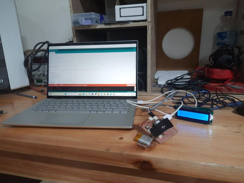
For such a simple procedure, it was taking a lot of time, so I decided to do debugging. So I decided to use Arduino.
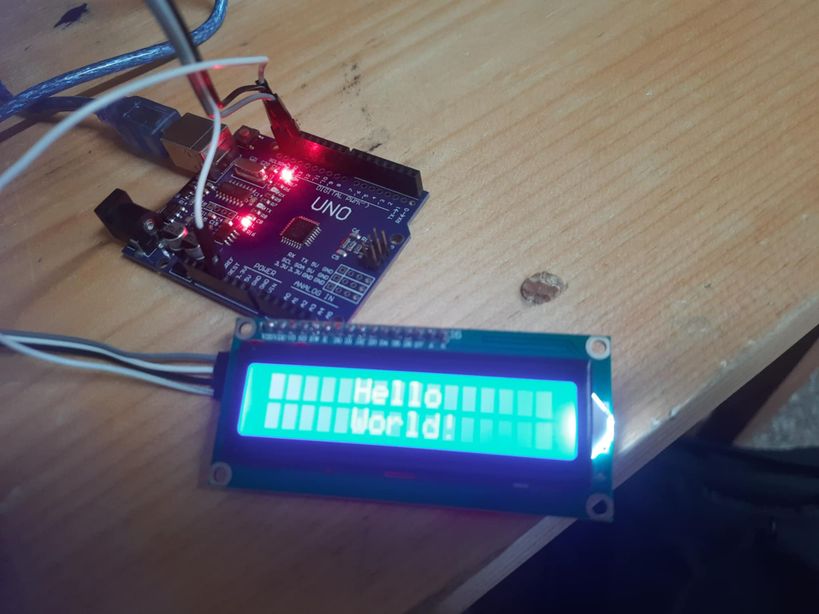
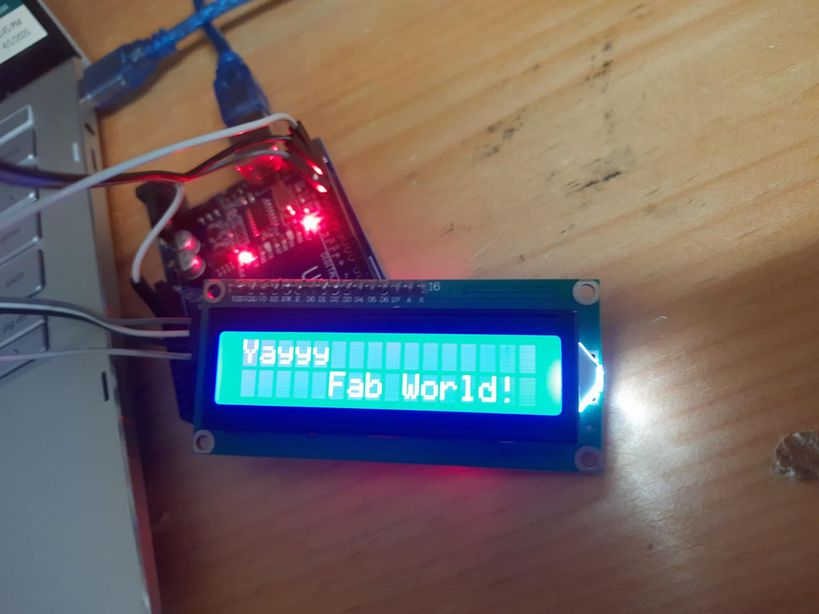
Then I just added a tiny tweek to the code and changed to words to Yayyy Fab World!
#include#include // Make sure you have this library installed // Set the LCD address to 0x27 for a 16 chars and 2 line display // This address is common for PCF8574 modules, but might vary. // If your LCD doesn't work, you might need to find its I2C address using an I2C scanner sketch. LiquidCrystal_I2C lcd(0x27, 16, 2); void setup() { Wire.begin(); // Initialize I2C communication lcd.init(); // Initialize the LCD lcd.backlight(); // Turn on the backlight lcd.clear(); // Clear any existing display content } void loop() { lcd.setCursor(0, 0); // Set cursor to the first column (0) of the first row (0) lcd.print("Yayy"); // Print "Yayy" lcd.setCursor(5, 1); // Set cursor to the sixth column (5) of the second row (1) lcd.print("Fab World!"); // Print "Fab World!" delay(500); // Keep the message displayed for 0.5 seconds // Optional: Flashing the backlight for effect (as in the example) // for (int i = 0; i < 5; ++i) { // lcd.backlight(); // delay(50); // lcd.noBacklight(); // Use noBacklight() to turn off backlight // delay(50); // } // lcd.backlight(); // Turn backlight back on after flashing // lcd.clear(); // Clear the screen after a delay // delay(500); // Wait 0.5 seconds before repeating }
OLED
OLED (Organic Light-Emitting Diode) is a display technology where each pixel emits its own light, resulting in perfect blacks, vibrant colors, and high contrast, unlike traditional LCD screens that require a backligh
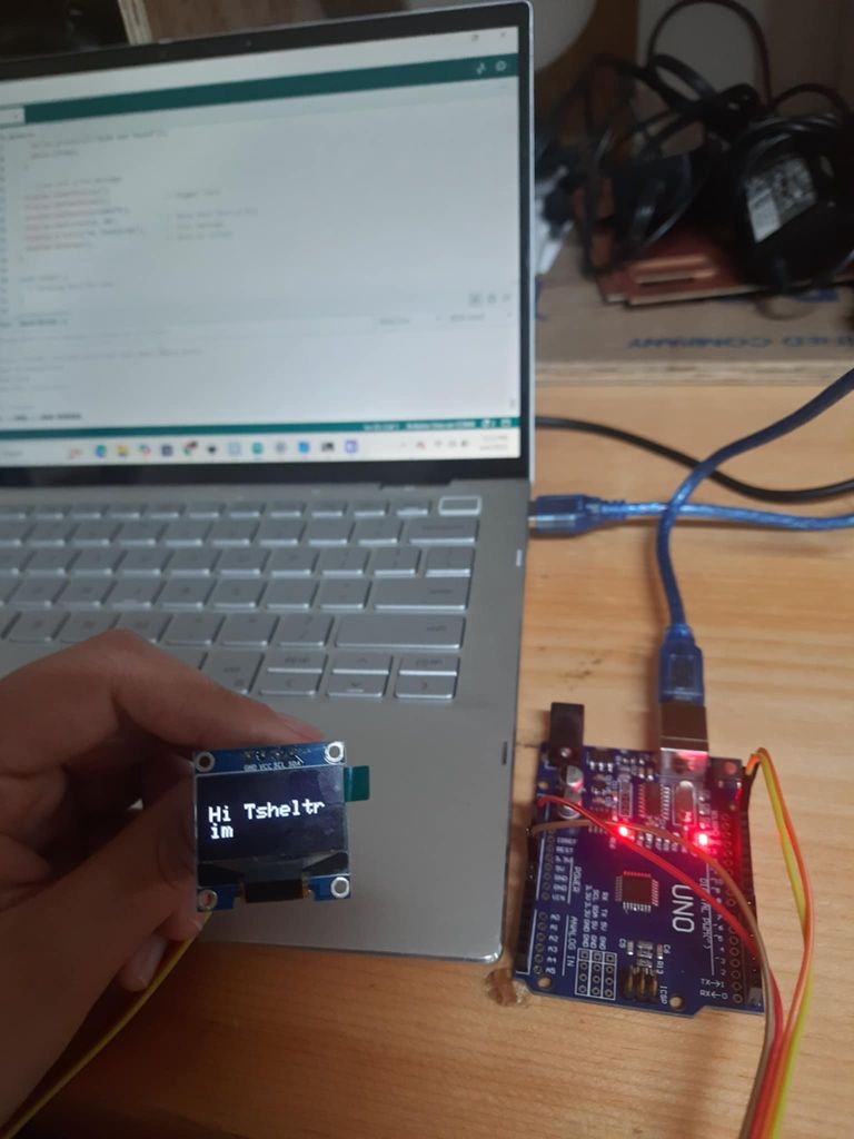
I also wanted to try with OLED so I used arduino to check if my OLED was functioning properly or not. And it was a success and it displayed "Hi Tsheltrim" To simply start, we need to download various Libraries such as Adafruit SSD1306-for controlling the SSD1306 OLED display and adafruit GFX Library-for graphics functions like text, shapes, lines, etc and finally Adafruit BusIO- which gets installed automatically when you install Adafruit SSD1306
#include <Wire.h>
#include <Adafruit_GFX.h>
#include <Adafruit_SSD1306.h>

// OLED display size
#define SCREEN_WIDTH 128
#define SCREEN_HEIGHT 64

// Create OLED display object
Adafruit_SSD1306 display(SCREEN_WIDTH, SCREEN_HEIGHT, &Wire, -1);

void setup() {
  Serial.begin(115200);

  // Initialize OLED
  if (!display.begin(SSD1306_SWITCHCAPVCC, 0x3C)) {
    Serial.println(F("OLED not found"));
    while (true);
  }

  // Clear and write message
  display.clearDisplay();
  display.setTextSize(2);              // Bigger text
  display.setTextColor(WHITE);
  display.setCursor(0, 20);            // Move text down a bit
  display.println("Hi Tsheltrim");     // Your message
  display.display();                   // Show on screen
}

void loop() {
  // Nothing here for now
}
This Arduino sketch displays the message "Hi Tsheltrim" on a 128×64 pixel OLED screen using the Adafruit SSD1306 and GFX libraries. After including the required libraries and defining the screen dimensions, an Adafruit_SSD1306 object is created to interface with the display. In the setup() function, serial communication is initialized for debugging, and the OLED display is started. If initialization fails, an error message is printed, and the program halts. Upon successful setup, the display is cleared, text size is increased to make it more readable, and the cursor is positioned vertically to center the message better. The message "Hi Tsheltrim" is printed and then displayed using display.display(). The loop() is left empty as no continuous operation is needed for this simple greeting display.
OLED Display Setup and Functionality
For the OLED display, both with the Arduino and my own board, the connections were consistent as they utilize the I2C communication protocol.
Connections to Arduino (for testing)
- VCC on the OLED to 5V on the Arduino
- GND on the OLED to GND on the Arduino
- SDA on the OLED to A4 (SDA pin) on the Arduino Uno
- SCL on the OLED to A5 (SCL pin) on the Arduino Uno
Connections to My Board
- VCC on the OLED to 5V on my board
- GND on the OLED to GND on my board
- SDA on the OLED to D4 (SDA pin) on the Xiao ESP32-C3 microcontroller (routed to a connector on my board)
- SCL on the OLED to D5 (SCL pin) on the Xiao ESP32-C3 microcontroller (routed to a connector on my board)
Importance of the GFX Library
The Adafruit GFX Library is necessary because the Adafruit_SSD1306 library relies on it for all graphic primitives. While Adafruit_SSD1306 handles the communication with the SSD1306 OLED controller, it doesn't contain functions for drawing text, lines, circles, or other shapes. That's where the GFX (Graphics and Fonts eXtension) library comes in.
Functions Used from the GFX Library
display.clearDisplay(): Clears the entire buffer of the display.display.setTextSize(2): Sets the size of the text.display.setTextColor(WHITE): Sets the color of the text.display.setCursor(0, 20): Sets the position for drawing text or graphics.display.println("text"): Prints text to the display buffer.display.display(): Sends the display buffer to the screen to make changes visible.
Without the GFX library, functions like setTextSize(), setTextColor(), setCursor(), and println() would not be available for the Adafruit_SSD1306 object.
Servo motor
A servo motor is a rotary or linear actuator that allows for precise control of angular or linear position, velocity, and acceleration in a mechanical system. It is an electric motor that converts electrical power into mechanical power
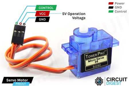
Image source
#include <Servo.h> // Include the Servo library

Servo myServo; // Create a Servo object

void setup() {
  myServo.attach(A5); // Attach the servo to pin A5
}

void loop() {
  // Sweep the servo from 0 to 180 degrees and back
  for (int pos = 0; pos <= 180; pos++) {
    myServo.write(pos); // Tell the servo to move to the specified position
    delay(15); // Wait for the servo to reach the position
  }

  for (int pos = 180; pos >= 0; pos--) {
    myServo.write(pos); // Tell the servo to move to the specified position
    delay(15); // Wait for the servo to reach the position
  }
}
This Arduino sketch controls a servo motor using the Servo library. A Servo object named myServo is created and attached to analog pin A5 in the setup() function. In the loop(), the servo is programmed to sweep smoothly from 0 to 180 degrees and back. This is achieved using two for loops: the first gradually increases the angle from 0 to 180, and the second decreases it from 180 back to 0. The myServo.write(pos) command moves the servo to the specified angle, and the delay(15) gives it enough time (15 milliseconds) to reach each position, creating a smooth sweeping motion.
Servo Motor Control with PWM
A servo motor requires a Pulse Width Modulation (PWM) signal to control its angular position. The signal looks like a series of pulses on a digital pin.
How the PWM Signal Works
- Frequency: Standard hobby servos typically expect a PWM signal with a frequency of 50 Hz (or a period of 20 milliseconds). This means a new pulse is sent every 20ms.
- Pulse Width: The width of the pulse (the duration for which the signal is HIGH within that 20ms period) determines the angle of the servo:
- Approximately 1000 microseconds (1ms) → one extreme (e.g., 0 degrees)
- Approximately 1500 microseconds (1.5ms) → center position (e.g., 90 degrees)
- Approximately 2000 microseconds (2ms) → other extreme (e.g., 180 degrees)
- Signal Representation: Graphically, the signal is a square wave where the HIGH duration varies, but the total period remains constant.
The microcontroller generates this precise timing using its PWM capabilities. The Servo.h library in Arduino simplifies this greatly, allowing us to use myServo.write(angle) directly, which internally calculates and generates the correct pulse width for the desired angle.
Servo Motor Connections on My Board
- VCC (Red wire) on the servo to 5V on my board
- GND (Brown/Black wire) on the servo to GND on my board
- Signal Pin (Orange/Yellow/White wire) on the servo to Digital Pin 7 on the Xiao ESP32-C3 microcontroller (routed to a connector on my board)
Digital Pin 7 was chosen as it’s a suitable PWM pin on the Xiao ESP32-C3. The code snippet used for the servo motor includes myservo.attach(7);, which correctly attaches the servo to GPIO pin 7 on the Xiao ESP32-C3.
NOTE: I compressed the output video with the command: ffmpeg -i m.mp4 -an -filter:v "setpts=0.5*PTS" -preset fast -crf 28 m_compressed.mp4 to speed up its playback by 2 times and also remove the audio from a video and compress it.
With my board
Soon enough I realized that my board was maybe too complex or it just did not work so I created a new 1. Rico san had adviced us to create a new generic board. These were our guidelines were creating it.
To that end, I would like to specify the following requirements for your 'Development Board'... Socket connections for your Xiao MCU
- Socket connections for your Xiao MCU
- A 5 pin connector (male or female type, up to you) connected to the 5V Xiao pin
- A 5 pin connector connected to the GND Xiao pin
- A 5 pin connector connected to the 3V3 Xiao pin
- A 2 pin connector connected to the TX and RX pins of your Xiao (the lower left and right pins)
- A 2 pin connector connected to the SCL and SDA pins of your Xiao (the 5th and 6th pins down from the top on the right side)
- A 4 pin connector for your Analog pins (A0 to A3)
- A 7 pin connector for your Digital pins that are not also Analog pins (D4 to D10)
- An LED and companion resistor connected in series with your 5V pin and GND
- An LED and companion resistor connected in series with your 3V3 pin and GND
- A 'Debugging' LED (ideally a different color from the Power LEDs) and companion resistor connected between a Digital Pin and GND
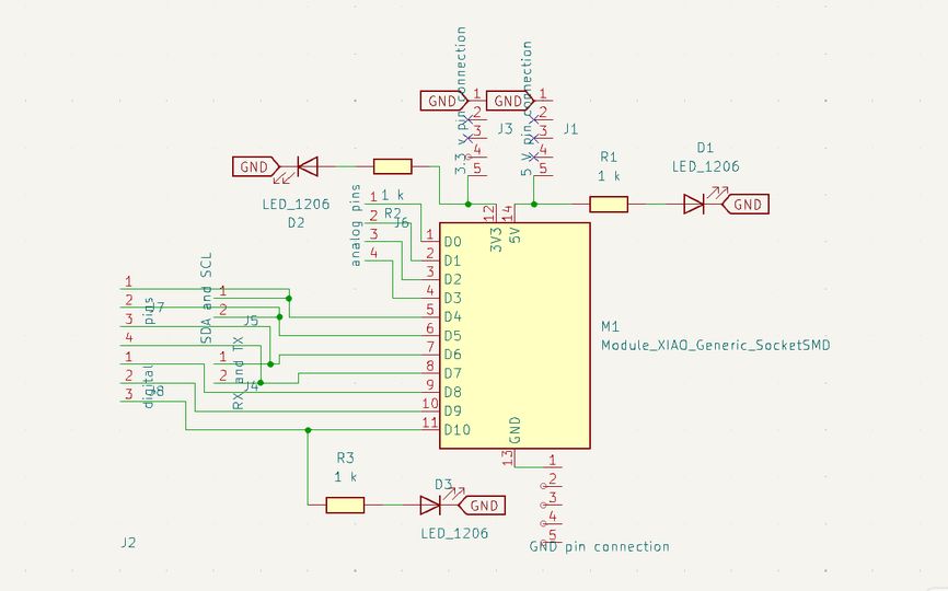
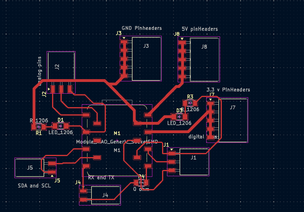
This is my schematic and my PCB.
Ummmm... This was my 1st schematic and pcb design of the board which I sent to sir Rico who graciously gave me feedbacks and suggestions that actually benefited my board a lot eventually making life easier for me! Thank you Rico san!
Then he sent me feedbacks and it were as follows:
- The 5 pin connectors for GND, 3V3, and 5V are not properly connected in the schematic. All 5 connection points must be connected to their respective MCU pin.
- Your D1 and D2 LEDs are currently floating and disconnected; they need to be connected to ground.
- What are these LEDs, and why are they connected in series?
- At the moment, you don't have LEDs to indicate if your 5V and 3V3 lines have power (Power Indicator LEDs).
- If you finish the connections this way, D1 and D2 will become programmable LEDs.
- J3 is in the same location as the USB connector for the Xiao, which might make it an awkward location for the connector.
- Consider pushing the connectors away from the MCU connector a bit more to make it easier to solder.
- Ensure there is a 1cm empty space around the MCU.
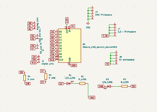
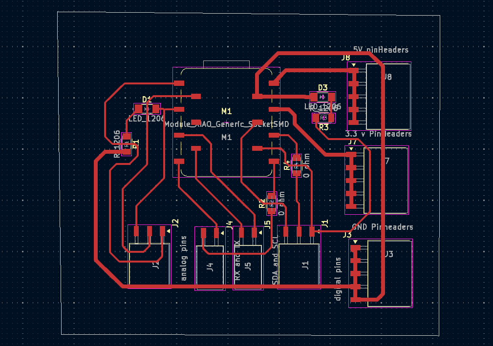
He also asked me to check out Shoko's documentation which was of great help as her PCB and schematic was very clean so I also tried my best to create a very clean looking PCB schematic using labels! These are my schematic and PCB.
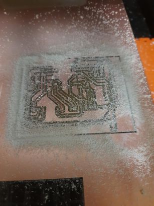
Milling and Soldering
Converting the design to rml files using MIT mods, milling it and soldering it is very important. You can refer to my past week's documentation to delve deeper into it as I did not redo the documentation. These are some of the pictures I took while milling and soldering it.
I milled my copper layer with 1/32 endmill as it was in the wrong container that was labelled as 1/64 bit so i used it and thats how the precision got messed up and some of the components went through a shot circuit and it was best to remill so i did it.
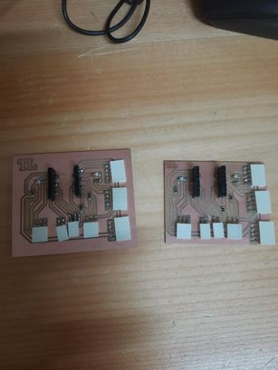
I systematically went through each component and trace, using the continuity tester on the multimeter to pinpoint the unintended connections. It was a painstaking process but essential to understand where the milling error had caused problems. The board on the right side is the 1st one which has a lot of short circuits, and the one on the left side is the one that is actually functional..
LCD
Then with my generic board I did all of the connections and the Wooohooo, the lcd worked. The code is the same as given above with the "Yayyy Fab World!" being displayed.
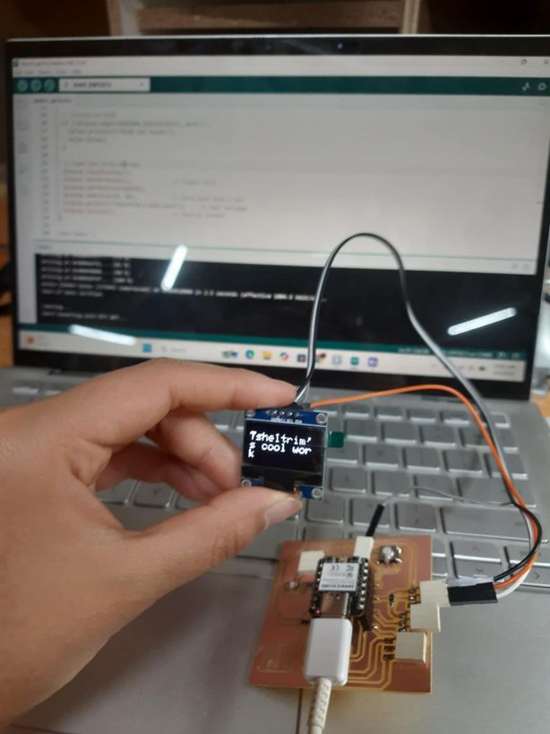
OLED
#include <Wire.h>
#include <Adafruit_GFX.h>
#include <Adafruit_SSD1306.h>

// OLED display size
#define SCREEN_WIDTH 128
#define SCREEN_HEIGHT 64

// Create OLED display object
Adafruit_SSD1306 display(SCREEN_WIDTH, SCREEN_HEIGHT, &Wire, -1);

void setup() {
  Serial.begin(115200);

  // Initialize OLED
  if (!display.begin(SSD1306_SWITCHCAPVCC, 0x3C)) {
    Serial.println(F("OLED not found"));
    while (true);
  }

  // Clear and write message
  display.clearDisplay();
  display.setTextSize(2);              // Bigger text
  display.setTextColor(WHITE);
  display.setCursor(0, 10);            // Move text down a bit
  display.println("Tsheltrim's cool work");     // Your message
  display.display();                   // Show on screen
}

void loop() {
  // Nothing here for now
}
This Arduino sketch is designed to display the message "Tsheltrim's cool work" on a 128×64 pixel OLED screen using the Adafruit SSD1306 and GFX libraries.
Servo motor
I compressed my video using ffmpeg usign the following command : ffmpeg -i servo_with_my_board.mp4 -an -filter:v "setpts=0.5*PTS" -preset fast -crf 28 servo_with_my_board_compressed.mp4
#include <Servo.h> // Include the Servo library

Servo myservo;

void setup() {
  myservo.setPeriodHertz(50);  // 50Hz for servo
  myservo.attach(7);           // GPIO 7 is a good PWM pin
}

void loop() {
  myservo.write(0);    // Move to 0 degrees
  delay(1000);
  myservo.write(90);   // Move to 90 degrees
  delay(1000);
  myservo.write(180);  // Move to 180 degrees
  delay(1000);
}
This Arduino sketch demonstrates how to control a servo motor by rotating it to fixed angles: 0°, 90°, and 180°, with 1-second delays between each movement. The Servo library is included to simplify PWM control. In setup(), the servo is configured to operate at 50 Hz—typical for standard servos—and is attached to digital pin 7, a PWM-capable pin. In the loop(), the servo moves sequentially to 0°, 90°, and 180°, with delay(1000) allowing time at each position. This creates a simple back-and-forth stepping motion useful for testing or demonstrating servo positioning.
Final Project Development
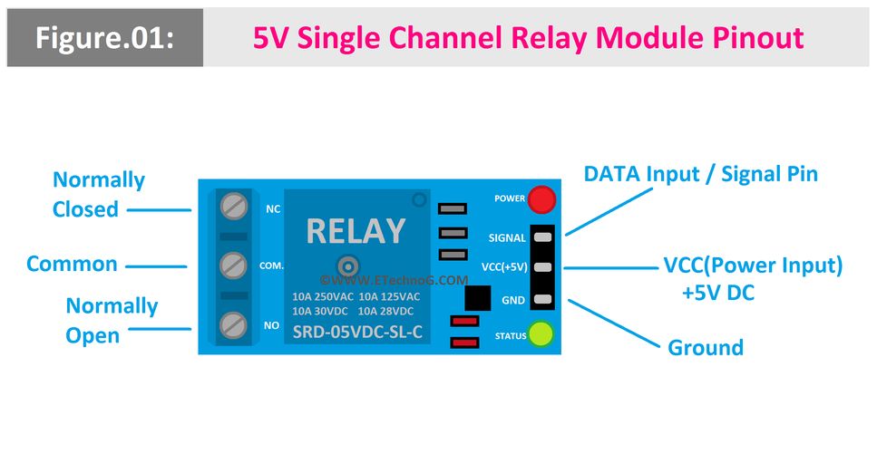
Relay module
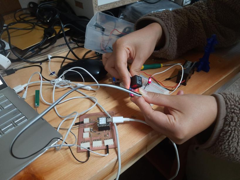
I decided to explore the relay module too as I will be using it for my final project so, I learnt about relay and then used it to switch on and off a LED with a breadboard and then connected it to a dc motor without a breadboard. I used a 9V battery.
My signal pin was 2.
The relay module is here. Image source
I used a 9V battery to control the DC motor. This is the code that I used both for the dc motor as well as the led bulb. This turns a connected device—like a DC motor or an LED bulb—on and off every second using digital pin 2. Here's a brief explanation of how it works:
void setup() {
  pinMode(2, OUTPUT);
}

void loop() {
  digitalWrite(2, HIGH);
  delay(1000);
  digitalWrite(2, LOW);
  delay(1000);                 // wait for a second
                  // wait for a second
}
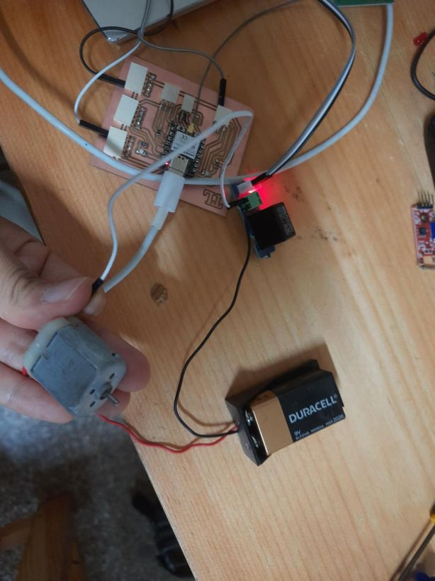
I used a breadboard here because I had to use a 1k resistor or else the voltage supplied by the 9V battery would have bombed my poor LED bulb, so to control the excess of it I used a breadboard.
Redesigning my enclosure
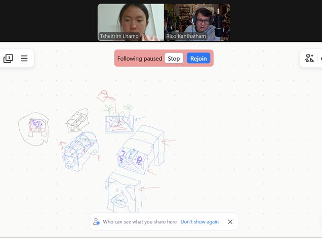
Then I had a session with my regional instructor sir Rico and clarified my doubts regarding the model for my final project. This was a briefing where I presented my model and then he suggested useful feedbacks that I will use to further enhance my design.
Key Modifications of my design for now
- The unique feature of my design will be that it will be divided into 3 modules-the electronics box, the plant placement box and the water reservoir so that I can scale up my project in the possible.
- The dimensions will be 20 cm by 40 cm by 30 cm.
- The face of the pig will serve as the electronic box, and it will be able to open and close by sliding it. The face features(the nose, eyes and ears) will be laser printed and engraved.
- There will be a plant placed in the middle module, and the moisture sensor and DHT22 will be placed inside it.
- The last module will serve as the water reservoir. That water will be pumped to the middle module with a relay passing through a pipe for which a hole has been placed already."
Files
You can access the files here
General purpose board - Tsheltrimduino
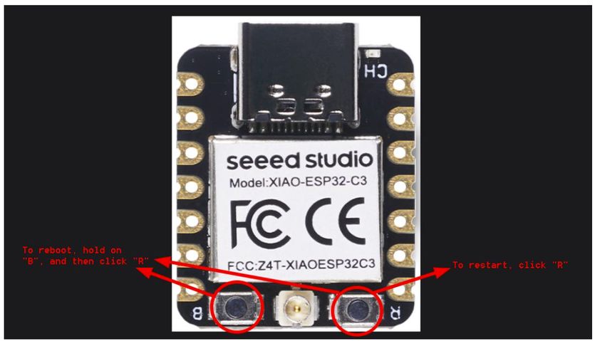
MAJOR ERROR!!
This week, i mainly suffered from not being able toupload my code from the Arduino Ide. Then I went through Thinely Wozer's documentation and found a fix. All I had to do was reboot my MC as SOON as I started uploading the code, and then restarting the MC once the code was uploaded. This image is borrowed from his website