
Roadmap
This week, our school kept us engaged in various activities and due to this some of my goals in my roadmap weren't completed on time as I would have liked. Regardless of it, I was able to complete all of my assignments on time.
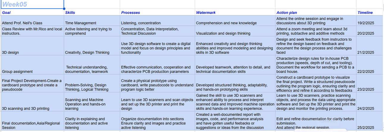
Table of Contents
Group Assignment
For the group assignment we had to find out the design rules for the 3d printing machine that we had in our lab.
3D Printer
At the DGI Aesthetic Centre, we have Prusa i3 MK3. And it is very popular because it is reliable and the prints are precise, it is open-source with a strong community support and has easy maintenance.
This is the 3D printer specifications that I created after learning about our printer. I learned a lot of new vocabularies that you can see in the software and vocabularies section. But a very interesting new word I learned was FDM (Fused Deposition Modeling) which is a 3D printing technology where a thermoplastic filament is melted and extruded through a nozzle to create objects layer by layer.
| Parameter | Value |
|---|---|
| Type | Fused Deposition Modeling (FDM)-(plastic filament is melted and laid down layer by layer to create an object) |
| Nozzle Diameter | 0.4mm |
| Max Print Speed | 200 mm/s |
| Layer Thickness | 0.1mm → 0.3mm |
| Filament Diameter | 1.75mm |
| Bed Leveling | Auto-Mesh Bed Leveling(automatically measures and adjusts for bed unevenness, ensuring a perfect first layer.) |
| Temperature | PLA → 218°C |
| Slicer | PrusaSlicer |
| Control | LCD screen, USB and SD card |
| Build Volume | 200 x 200 x 200 mm |
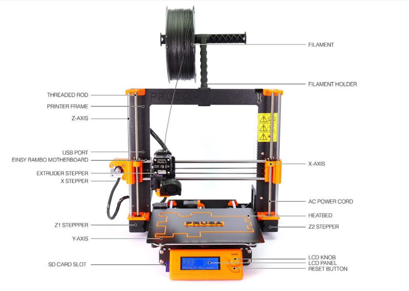
The 3D printer that we have at our Fab Lab is the Prusa i3 MK3, and here’s a well labelled diagram of the printer. Image Source
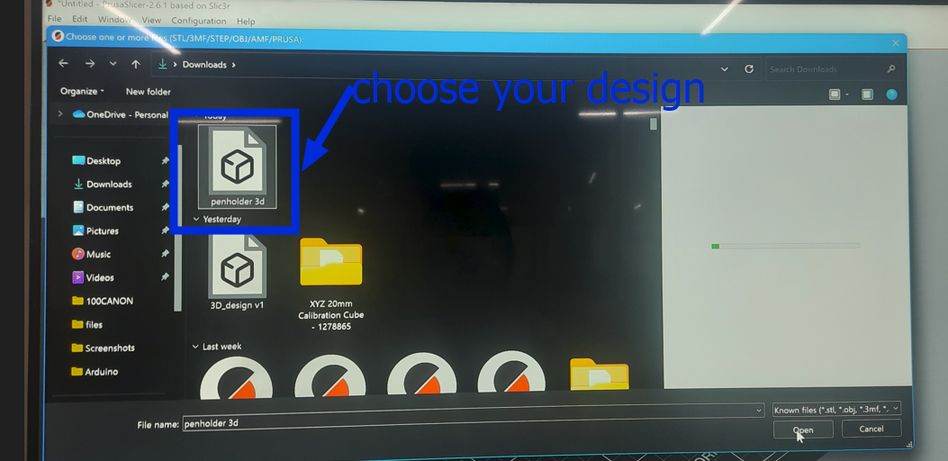
Slicing
Slicing in 3D printing is the process of converting a 3D model (like an STL file) into G-code, which the printer can understand. G-code is generated from slicer software like Prusa Slicer that we often use here, translating STL files into machine-readable instructions. For the design test rule we downloaded it from here. After slicing, we downloaded the file, and then printed it. You can access the group assignment here 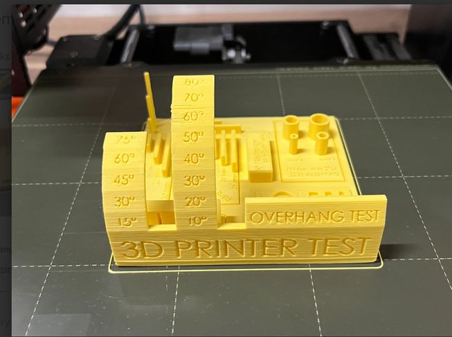
Conclusion
Our printer struggled with embedded letters, though they remained readable, especially when larger. The vertical test performed well up to 6 cm, after which the layers became messy and fuzzy. Bridging was surprisingly successful, but the filament distribution was uneven. The printer handled angles smoothly up to 60 degrees, beyond which the surfaces became rough and needs support.
Satey Measures
- These are important points to remember while printing a design.
- Always watch your printer – leaving it unattended can be risky.
- Temperature matters – too hot or too cold can ruin a print.
- Start off your print at a slower speed to make sure that your foundation is strong.
- Speed affects quality – printing too fast can cause issues.
- Slicing is important – a bad slice can lead to failed prints.
Individual Assignment
For this week we had to 3d scan an object. For it we used Polycam which can be used to quickly scan and generate 3D model. It is user friendly and simple to use and you can download it on the App Store/Playstore.I found this great user interface in Yangtshel Wangyel's website.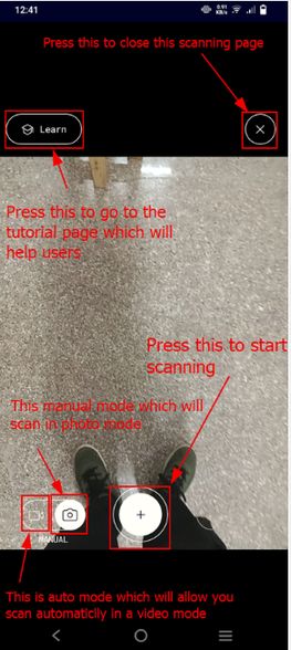
How to scan?
Scan the object and move slowly around the object, keeping it in focus.
A pro tip: Ensure good lighting for better details.
NOTE: Capture all angles, including the top and bottom.
BUT
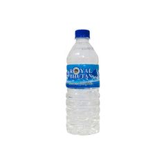
I made a mistake: I tried to scan a transparent mineral water bottle. The scanner struggled to scan transparent bottles because they lack surface details, and light passes through them, confusing the scanner.
I chose to scan a transparent water bottle that is common here in Bhutan but after I uploaded the model, I mistakenly deleted the images so I got this image from Google.
Image source.
📸 Scanning Process
The scanning process with Polycam involved me moving my mobile phone steadily around the object I wanted to capture. The app uses the phone's camera and sensors to detect the shape and surface details from different angles. 1 It's kind of like taking a video while slowly circling the object, but instead of just recording images, it's actively building a 3D model in real-time.
The application provided a few key visual cues during the scanning process:
- Live Mesh View: As I moved the phone, I could see a 3D mesh of the object being created on my screen in real-time. This allowed me to see which areas had been captured and which hadn't.
I believe a uniform, non-reflective background would significantly improve the water bottle scan.
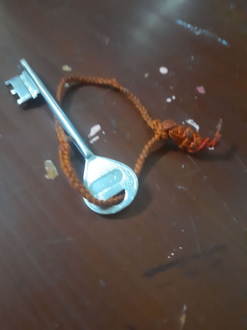
So the results werent great so lesson learned: never scan a transparent object because it confuses the scanner! Then I decided to scan my house key and it turned out great!
For the next assignment I had to design and print an object that would have been hard to print using subtractive method.Then we 3d printed an object for which we used prusa slicer too. Now what is subtractive method? and what is additive method?
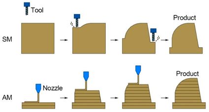
Additive Manufacturing
Additive manufacturing is basically a process of creating 3D objects by adding layer by layer of a material based on a digital model. This allows for complex geometries and customization.
Subtractive Manufacturing
Subtractive manufacturing involves removing material from a solid block to achieve the desired shape, usually through processes like milling, turning, or grinding. But it can create a lot more waste than the additive manufacturing process. This is a very helpful image that helps you understand and visualize it better.
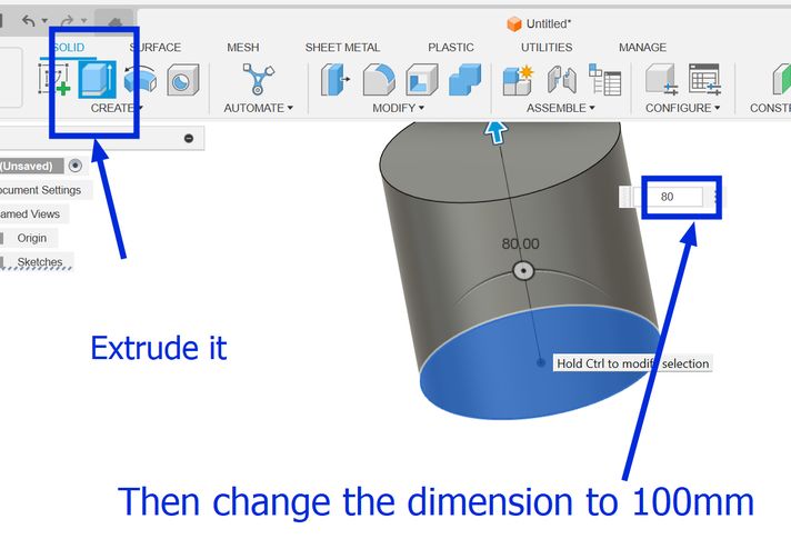
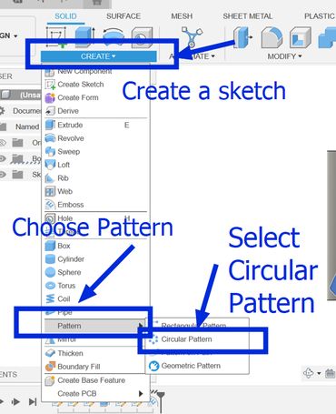
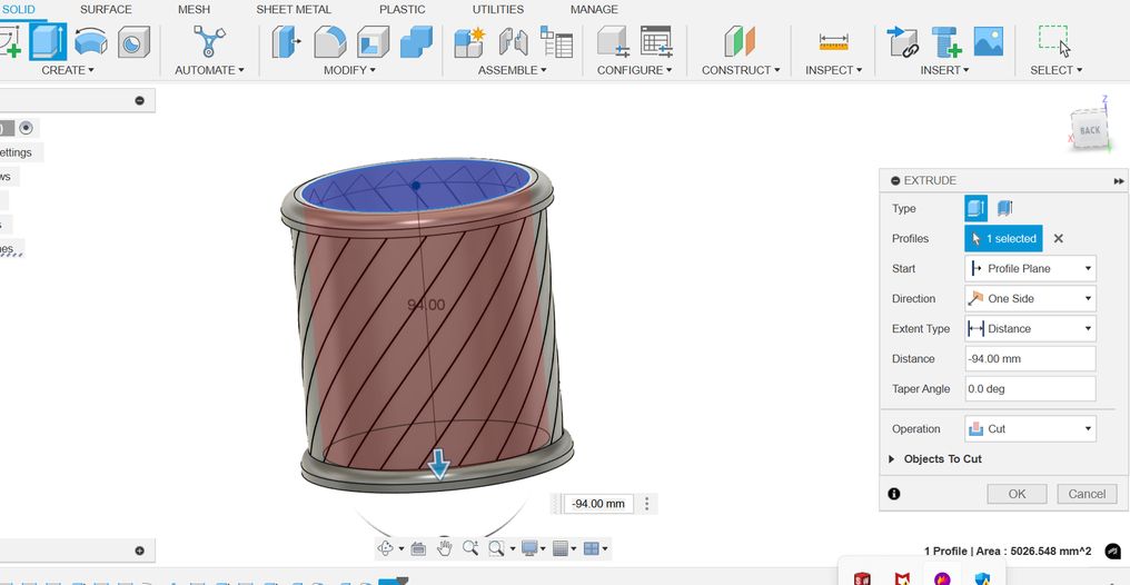
I will be creating a pencil or penholder that will have holes in between. It will be slanted in a certain angle and it will look very cool(according to me of course). Firstly open fusion and follow the instructions given.
Then go to Modify and press move/copy and then a small tab will appear where you should change the "move objects default setting" to "sketch objects." Then you will be able to rotate and move the object or sketch that you choose.
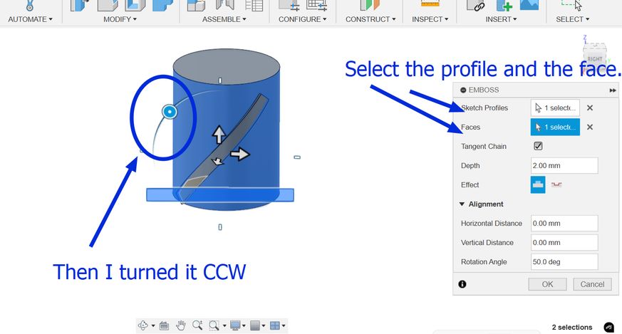
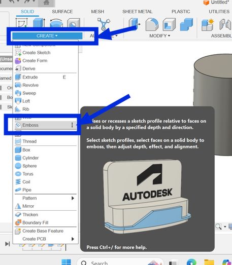
Then I used the emboss tool which is basically a raise or recess a sketch profile onto one or more faces of a solid body. Simply put, it is like a shape (like a letter or a logo) in 2D. Then, the Emboss tool lets you press that 2D shape onto the surface of your 3D object, making it either stick out (like a raised stamp) or go in (like a stamp that leaves an imprint).You get to decide how deep or how high the "stamp" goes. It's a way to easily add details like logos or text to your 3D models.
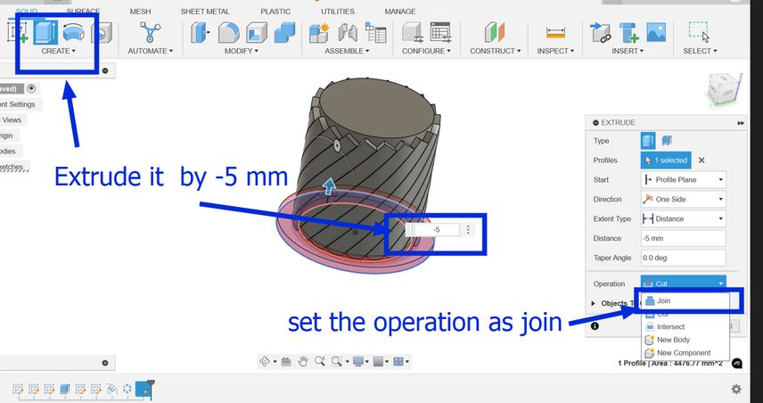
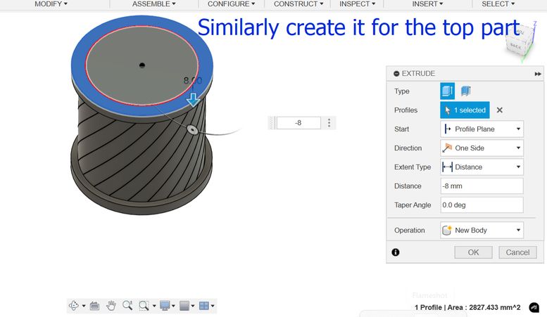
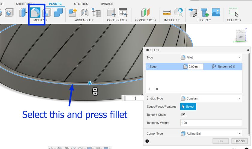
Then choose an edge and then select fillet and enter the value which was 5 in my case and I did it for both the top and bottom part.
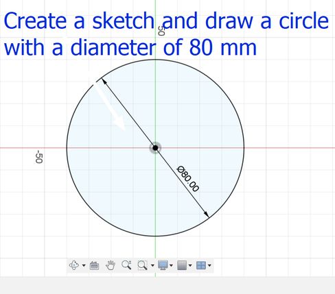
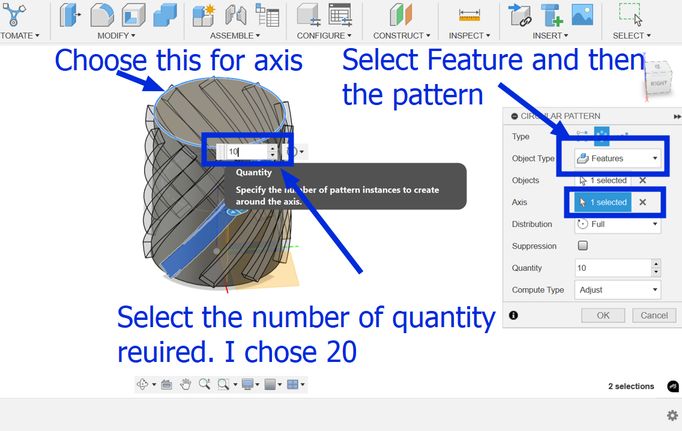
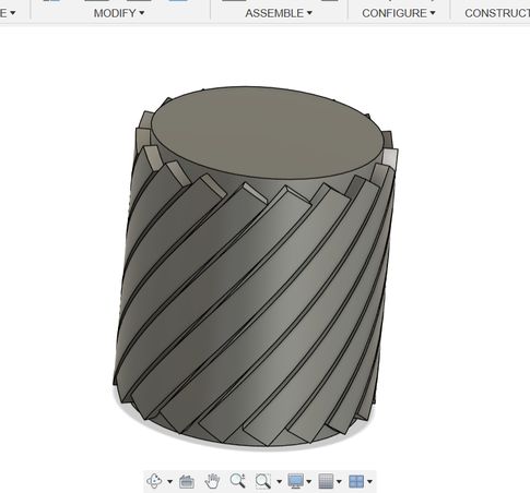
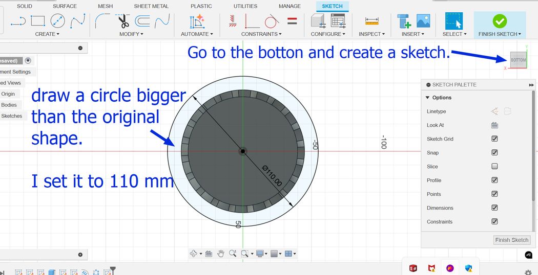
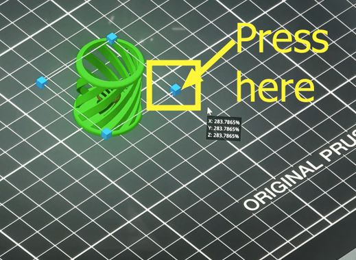
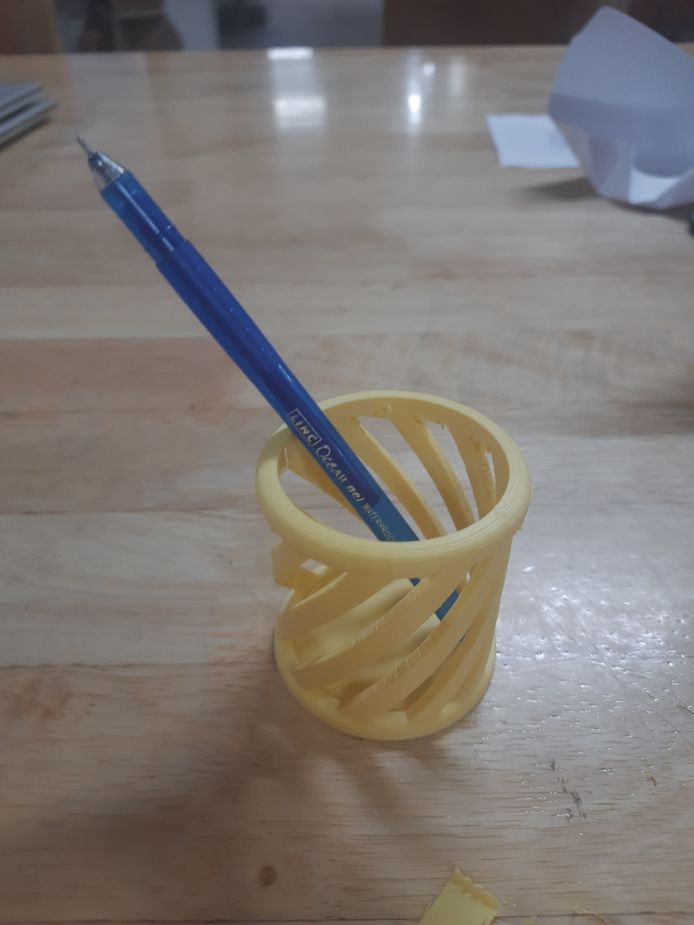
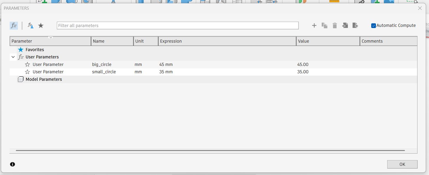
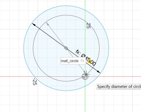
And finally create a new sketch and draw a circle of diameter 80 mm and extrude it downwards to make a hole! but Ooops! Its not what I envisioned it to be, I want the holes to be a bit bigger so now I go back to my sketch and make the circular pattern number to 10 and this is how it looks. I tried several different numbers such as 20, 28, 15 and 13 which always gave an undesired output. Then the number 10 for the circular pattern gave me the design that I had in mind so I stuck to it.
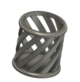
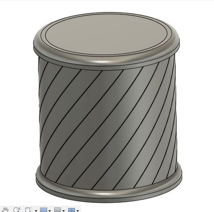
Yipee!!!! Finally it is done.

Then
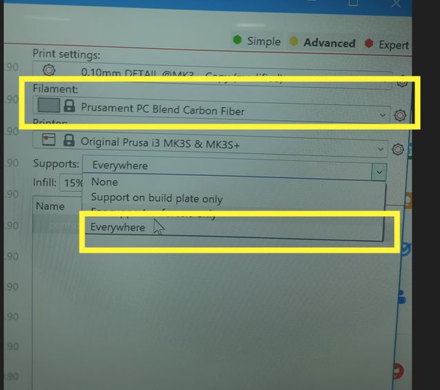
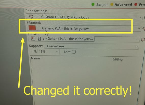
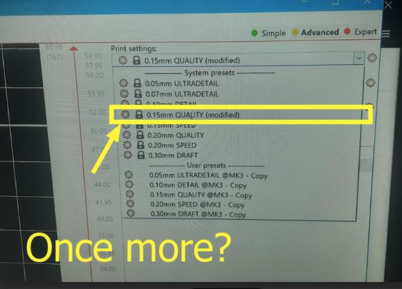
Before printing, we must set the layer height, the wall thickness and the infill which are important essentially as the infill affects the object’s internal strength and material use, the layer height impacts the surface smoothness and detail resolution and the wall thickness ensures the outer shell is strong enough, affecting durability.
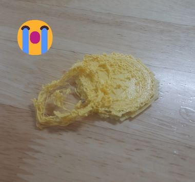
And Ooooooooops! a disaster. now to identify the error, we mistakened the yellow filament for another one so we tried again!
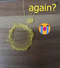
AND FINALLY!!!
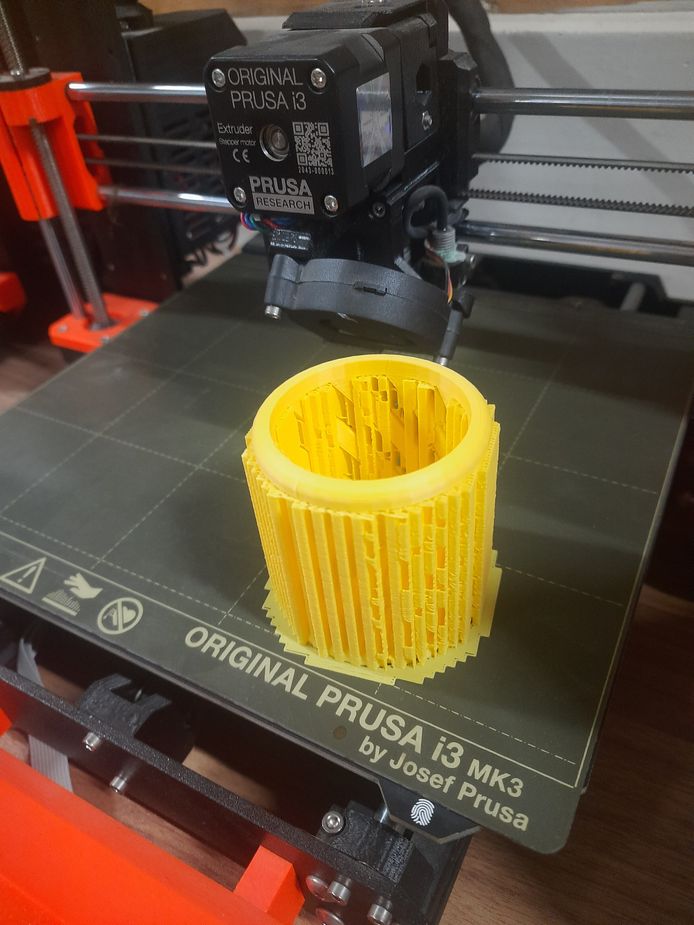
I did no post processing as when i removed the supports manually, it came off precisely and smoothly.
Why did I choose to make it?
A circular pen holder is additive because you typically build it up using tools like extrude or revolve, which add material to form the shape.
If it were subtractive, you'd start with a bigger solid block and carve out the cylindrical shape by removing material.
Holes are Part of the Design, it is not subtracted – unlike subtractive manufacturing (where holes are drilled or cut out), in additive manufacturing, the holes exist from the start as part of the 3D model.
Well turns out my design doesnt fit the category of being a design hard to be produced by subtractive manufacturing so I had to redo it! Woww after all of that hardwork right! Well, no complaints because my designing abilities improved through that. God planned it all. So without any further a do..
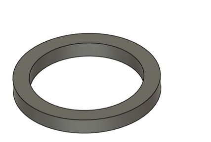
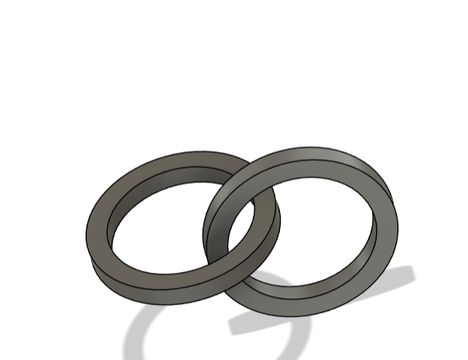
For this chain, subtractive methods (like milling or turning) would require work by removing material from a solid block. For a chain, where the links need to be interconnected with a specific shape, achieving this precisely with subtractive methods would be very challenging.
Week 05 Progress!
This week our local instructor assigned each of us our support instructors[fab academy students who have graduated last year] and I got 2 great mentors for fab academy namely Ngawang Pemo Dukpa and Yangtshel Wangyel. Then I went through their websites and in azhim Ngawang's website, I saw that she created a pseudocode to understand the workflow of her project better and then i thought why not do it myself. Then I gave the AI-Chatgpt this prompt, "Generate a pseudocode for an automated greenhouse using various sensors and actuators, including DHT22, Light Sensor (LDR), Soil Moisture Sensor, and actuators like Heater, Water Pump, and ventilation system. The main loop should read sensor data send the information to the microcontroller and decide whether to activate or deactivate actuators based on sensor thresholds while including a delay for the next cycle.
However then I had to edit some of it myself because I did not find it satisfactory as instead of saying activate fan if the temperature is too high, it said to activate ventilation which was kinda vague. Otherwise it did a great job
BEGIN

    // Initialization
    Initialize Temperature Sensor (DHT22)
    Initialize Light Sensor (LDR)
    Initialize Soil Moisture Sensor
    Initialize Actuators (Heater, Water Pump, Fan)
    Initialize Display/Control Interface

    // Main Loop
    WHILE system is running DO

        // Read Sensor Data
        temperature <- Read Temperature Sensor (DHT22)
        humidity <- Read Humidity Sensor (DHT22)
        light_level <- Read Light Sensor (LDR)
        soil_moisture <- Read Soil Moisture Sensor

        // Control Logic
        IF temperature < MIN_TEMPERATURE THEN
            Activate Heater
        ELSE IF temperature > MAX_TEMPERATURE THEN
            Deactivate Heater
            Activate Fan
        ENDIF

        IF humidity < MIN_HUMIDITY THEN
            Activate Humidifier (if available)
        ELSE IF humidity > MAX_HUMIDITY THEN
            Activate Fan
        ELSE
            Deactivate Fan
        ENDIF

        IF soil_moisture < MIN_SOIL_MOISTURE THEN
            Activate Water Pump for IRRIGATION_TIME
        ELSE
            Deactivate Water Pump
        ENDIF

        // Display Data
        Display Temperature, Humidity, Light Level, and Soil Moisture on LCD/Interface

        // Wait for next cycle
        Delay(SYSTEM_UPDATE_INTERVAL)
    ENDWHILE

END
Cardboard prototype
Moreover we were suggested to create a cardboard prototype to help us visualize our design by providing valuable insights into our project's functionality.
This prototype took me about 5 hours to create. This activity has helped me understand the structural and functionalities of my design better. Thus I would recommend everyone to create fast cardboard prototype initially as it helps a lot.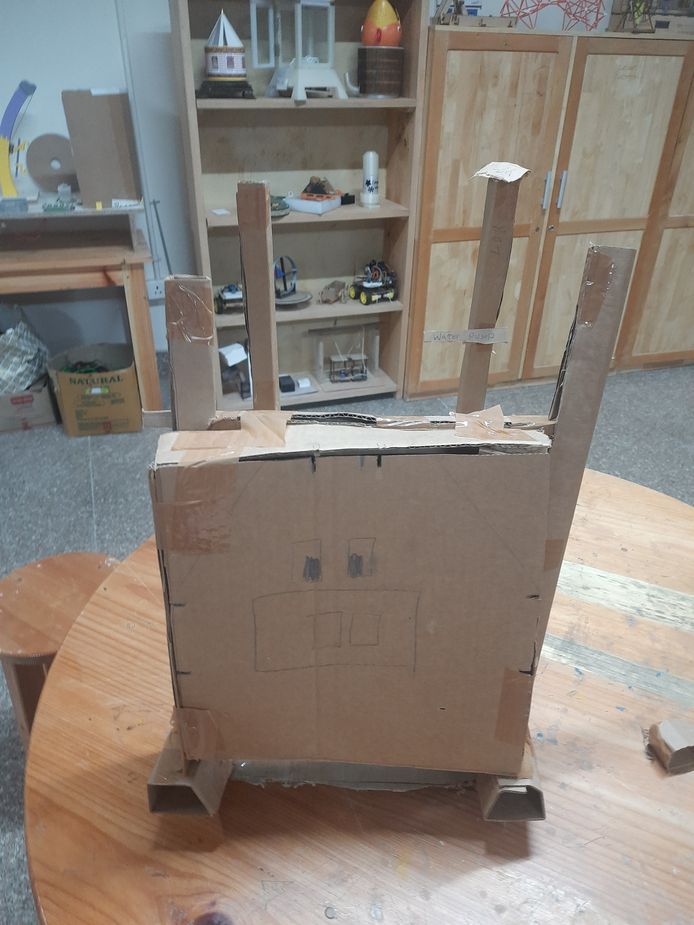
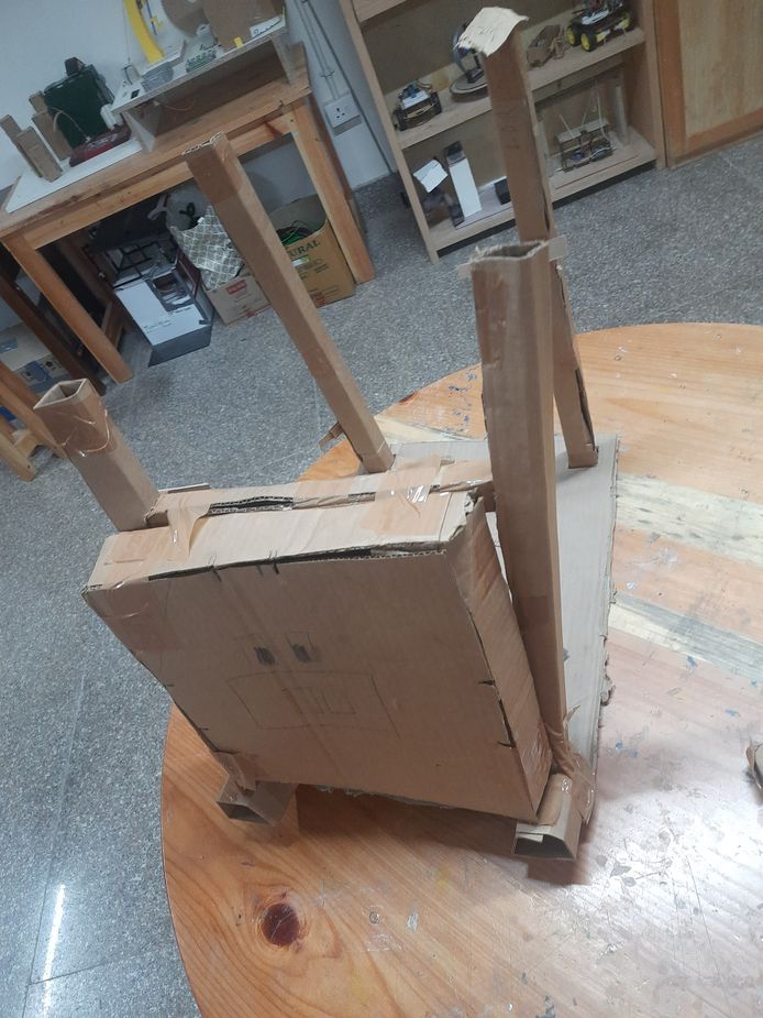
My design consists of a flat base with four square holes at the corners, each measuring 3 cm wide and spaced 2 cm apart along the x and y axes. Four 3 cm × 3 cm columns are inserted into these holes, and elevate the base by 5 cm. Then I created a 3D box and added facial features to resemble a pig. To enhance stability, I placed a horizontal column between two upright columns for additional support. Next, I added 2 small cubes of dimensions 5 cm x 5cm x 5cm on the base where the horizontal column was placed and positioned the pig's face on it. Finally, I used duct tape to secure all the components together.
But I think I have realized the flaws in my design so i wil be creating another cardboard prototype soon.
Files
You can access the files here 3D design of the penholder
and for the Chain