
Roadmap
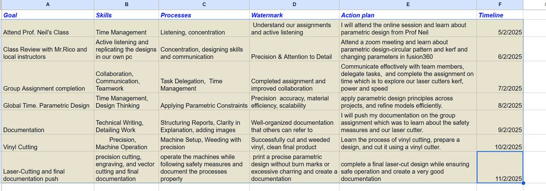
This week's planning phase was different. Where we initially created timetables, this time our local instructor suggested to create our very own roadmap. A roadmap is a structured plan that outlines the key learning objectives, content, skills, processes and watermarks the students will acquire over a certain period of time- timeline (such as a week, month or year).
"These processes help the learner make connections with existing knowledge and experiences and create new knowledge. Processes also help the learner apply and transact this knowledge with others in the community. Along with processes, learners will use mechanisms to learn, interpret, analyse and synthesize both existing knowledge and new knowledge. These mechanisms are termed ‘skills’ by the Bhutan Baccalaureate. All learning environments leave lasting impressions on the learners who participate in it. The practices and culture that a learning environment creates has the potential to impact the character and attitude of the learners for the rest of their lives. These impressions are called ‘watermarks’ by the Bhutan Baccalaureate. Watermarks are the traits and characteristics that manifest in a learner in specific situation or conditions." - Bhutan Baccalaureate
Table of Contents
- Group Assigment
- Individual Assignment
- The
<a>tag defines a hyperlink. href="https://www.example.com"specifies the destination URL.target="_blank"makes the link open in a new tab.- The
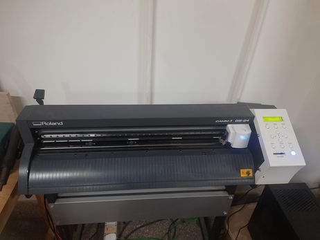
<img>tag displays the image, making it clickable. - Model: Roland CAMM-1 GS-24
- Software: Roland CutStudio and Adobe Illustrator
- Cutting Area: Maximum 584 mm × 25000 mm
- Maximum Material Thickness: Around 2.5 mm (0.1 inches)
- Cutting Speed: 10 to 500 mm/s (all directions)
- Usable Tools: Roland CAMM-1 series blade
- Settings:
- Textile Vinyl: Speed: 15 cm/s / Force: 90gf
- Copper Vinyl: Speed: 1 cm/s / Force: 40gf
Assignments
Group Assignment :
-Characterize your lasercutter’s focus, power, speed, rate, kerf, joint clearance and types.
-Document your work to the group work page and reflect on your individual page what you learned
Individual Assignment:
-Design, lasercut, and document a parametric construction kit, accounting for the lasercutter kerf, which can be assembled in multiple ways.
-Cut something on the vinyl cutter.
Group Assigment
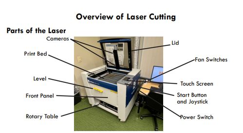
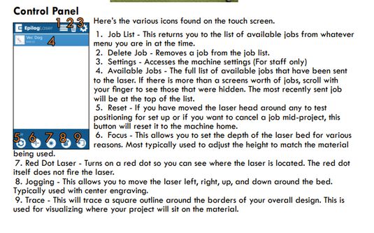
This week we had our 1st group assignment which was to characterize our lasercutter’s focus, power, speed, rate, kerf, joint clearance and types. As for the documentation, we all decided that we will take turns documenting the group assignments every week. You can access the group assignment here Before we started experimenting, our local instructor gave us a brief lesson on how the laser cutter works, as well as the mechanics that it uses to function. Before we started, we went through the different parts of a laser cutting machine, and I found this quite useful image from acho Thinley Wozer's website while going through it.
In acho Thinleys website, when you click on the image you get redirected to a link, then I wondered how and asked chatgpt[AI ] about it. The prompt and answer is given below.
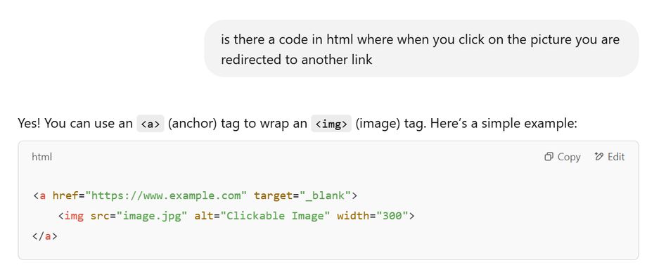
The explanation provided is that:
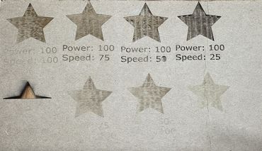
Then, we got started on experimenting how the “speed” and “power” settings could change the outcome of the cut. And we concluded that the best speed is 25 and the best power is 100 for our lasercutter.
After that, we started to find out the kerf of our laser cutter. But before that, I think it’s important to understand what kerf is.
Kerf is basically the lasers width. It is how much material is taken out of your final product when you cut something. This material loss happens because the laser also has a certain mass, and this means that the laser itself unintentionally cuts off some of the material that you’re cutting. This is important because it helps pieces fit together just right after they’re cut, so they’re not too loose or too tight
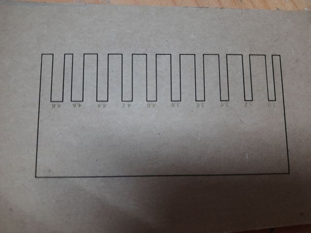
To measure the laser kerf accurately, use a caliper (digital or vernier) or a micrometer, as these tools provide precise measurements in millimeters (mm).
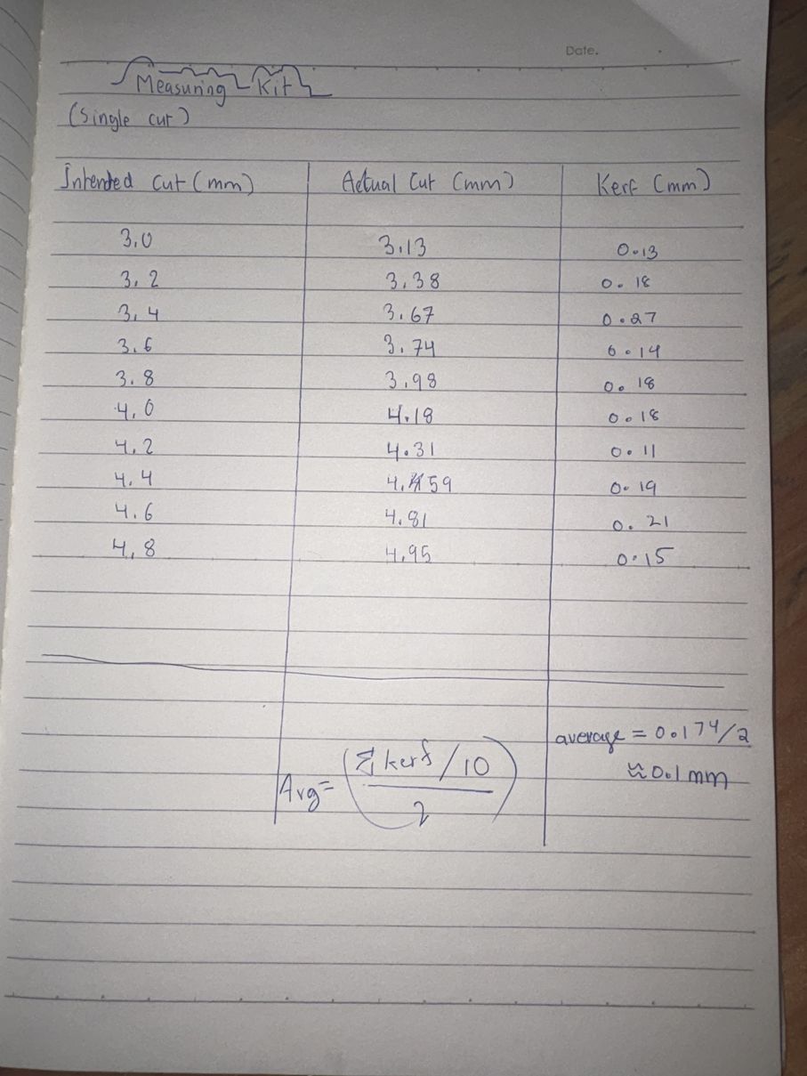
Then we subtracted the intended cut from the actual cut and got the difference. Then we added all of the differences and found out its average and divided it by 2. Dividing by two accounts for the fact that kerf affects both edges of a cut, giving a precise value for design adjustments.
Safety measures-VIR[very important reminder]
Fire Hazard
Laser systems generate high temperatures, especially during vector cutting, which can pose a fire risk, particularly with materials like acrylic.
✅ Always stay with the laser while it is in operation.
Safety Features
The Epilog Model 16000 & 17000 laser systems have safety features like safety enclosures, interlocks that de-energize the laser when doors are open, visible emission indicators for the Laser Diode Pointer, and more. Do not remove panels and NEVER defeat the door interlocks.
Laser Safety
These laser systems are Class 2 laser products and conform with safety standards.
Do not gaze directly into the laser beam.
NEVER operate the engraver without protective covers on at all times, or look directly into the Laser Diode Pointer.
Electrical Safety
The AC input power is potentially lethal. Do not remove access panels while the machine is powered, and do not make or break electrical connections while power is applied.
Do...
Operate the machine under proper ventilation and housekeeping using the Laboratory Hood
Keep the machine clean
Always remain with the machine when in use
Operate the engraver while unattended
Operate it without proper ducting or ventilation
Engrave or vector cut PVC-based products
Modify safety enclosures
Individual Assignment
Design, lasercut, and document a parametric construction kit, accounting for the lasercutter kerf, which can be assembled in multiple ways.
Cut something on the vinyl cutter.
Vinyl Cutting Machine
This week, we had to use vinyl cutting machines and cut anything and I cut a bunch of stickers to design the laptop. We also had to create a parametric design and use it to create a bunch of shapes. I enjoyed it a lot and. A vinyl cutter is a type of computer-controlled machine tool. Basically it is a CAD cutting which is a process in which graphics, letters and other vector designs are accurately cut from material using a cutter. The cutter is usually a blade. This blade is used to cut out shapes and letters from sheets of thin plastic also known as vinyl.
Vinyl Cutting
I decided to decorate my pc with the stickers i cut from vinyl cutter. To customzie my laptop I printed few images from pinterest and just like a little child, I was really excited while cutting the vinyl and I felt really happy while decorating my pc with it.
Material Setup:
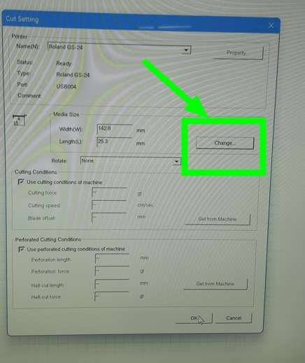
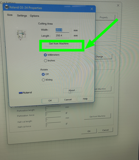
To load the vinyl into the Roland CAMM-1 GS-24 vinyl cutter, I cut a sheet of vinyl and then made sure the lever on the back of the machine was in the "release" position. Then, I unrolled the vinyl sheet and fed it from the back, aligning the edges with the blue guides on the machine. I adjusted the pinch rollers, ensuring they were positioned within the white markers and were firmly pressing down on the vinyl to grip it. Once the vinyl was correctly aligned and gripped, I moved the lever to the "lock" position. After locking the vinyl in place, I selected the appropriate feed mode (e.g., Roll, Sheet, or Edge) on the machine’s display, depending on how I loaded the material. The machine then automatically measured the width of the loaded vinyl, which would be reflected in the CutStudio software.
Once the vinyl was measured, I checked the display panel to confirm the dimensions and that no errors were shown before starting the design setup in CutStudio.
How to Cut Stickers?
I started by importing my image onto Cutstudio using the import tool in the file tab. You can access the pig and the death here. 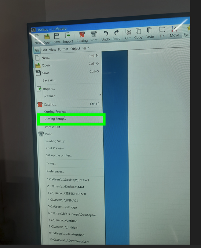
Then right click>image outline>extract contour lines>press ok.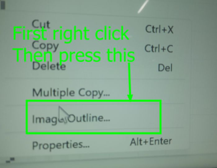
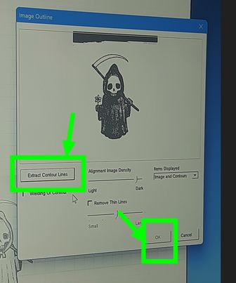
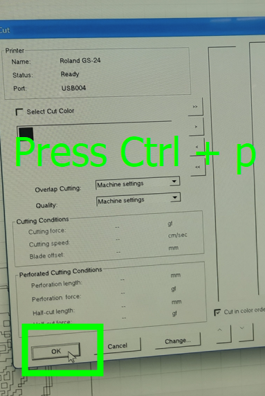
Then, just CTRL+P to cut out the sticker.
Weeding basically refers to the process of removing the excess vinyl material from around the design or lettering that has been cut by the vinyl cutting machine.
Vinyl Cutting Process and Settings
To send the print command to the vinyl cutter, I used the shortcut Ctrl + P. This initiated the cutting process with the settings I configured beforehand. The three main settings that influence the vinyl cutting process are speed, force, and blade depth.
1. Speed
The speed of the vinyl cutter plays a crucial role in the quality and safety of the cut. If the speed is too high, the design may not be cut accurately, and in the worst-case scenario, the blade could snap. It’s important to keep the machine at its recommended speed, which also depends on the type of blade used. I used a 45-degree blade, for which the ideal speed is 20 cm/s.
2. Force
The cutting force determines how much pressure the blade applies on the vinyl. If the force is too high, it may cut through the backing layer beneath the vinyl, damaging the design. On the other hand, too little force may result in incomplete cuts. The correct force setting depends on the blade type and the thickness of the vinyl. I used a 3mm vinyl sheet, and the recommended force is 50 gf.
3. Blade Depth
The blade depth is adjusted manually by rotating the threaded blade holder. To determine the correct depth, I lightly pressed the blade on the vinyl and dragged it slightly. The blade should cut only through the vinyl layer and not the protective backing layer. Proper blade depth ensures clean cuts without damaging the backing.
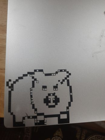
Final Outcome
After applying these settings, the vinyl cutter completed the job accurately. Here's how the design looked after the cutting was finished:
Transfer Process:
I transferred the pig and the "death" designs to the computer as vector graphics. The pig and the "death" image was a jpeg image which i converted to an SVG file. I used transfer paper to move the cut vinyl designs from their original backing to the laptop surface. I applied the transfer tape to the vinyl, pressed it to ensure good adhesion, then carefully peeled it off, lifting the vinyl design. Finally, I positioned the transfer tape with the vinyl on the laptop and pressed it again before slowly peeling away the transfer tape, leaving the stickers adhered to the laptop.
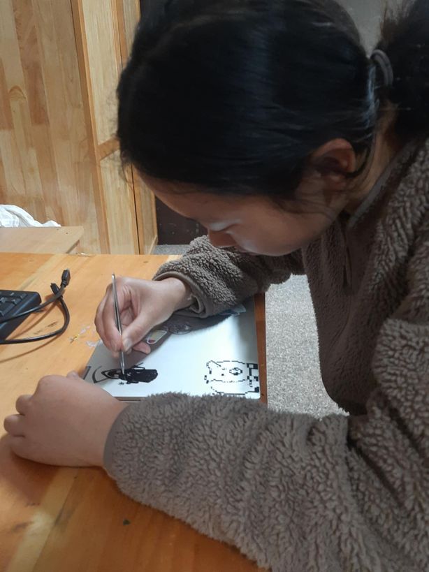
Weeding!!
Weeding in vinyl cutting refers to the process of removing the excess, unwanted vinyl material from the output design, leaving behind only the desired image or lettering. The weeding process was done manually after the vinyl cutter had finished its job. I used a weeding tool (a tweezer) to carefully remove the excess vinyl around the pig outline and the unwanted parts of the "death," leaving only the desired shapes on my laptop.
Parametric Designs
For this week, we had to create a Parametric Construction Kit, which is basically a customizable set of pieces that fit tightly together without glue or screws, allowing for easy assembly of various structures.
The term “parametric” refers to a design approach where geometric parameters can be adjusted to create variations in size of a model or structure. Parametric design allows for flexibility and adaptability in design creation.
I wanted to create lots of random objects that would be fun. I decided to use Fusion360 to create my designs.
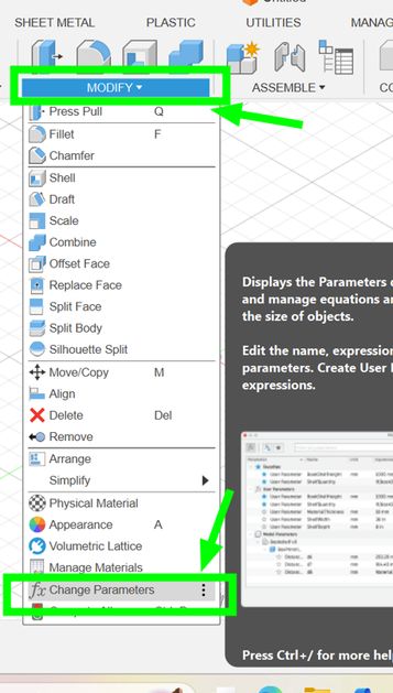
Firstly, go to Modify > Change parameters
SPOILER: I made a mistake by assuming the material thickness as 4 instead we used a cardboard with a thickness of 2 mm, so I had to change the thickness in the change parameters section later on. Keep in mind to check the material thickness and don't assume it because it can spoil your design.
....
This is my timetable for the week. The red highlight means that I havent been able to follow up with that particular program or schedule.
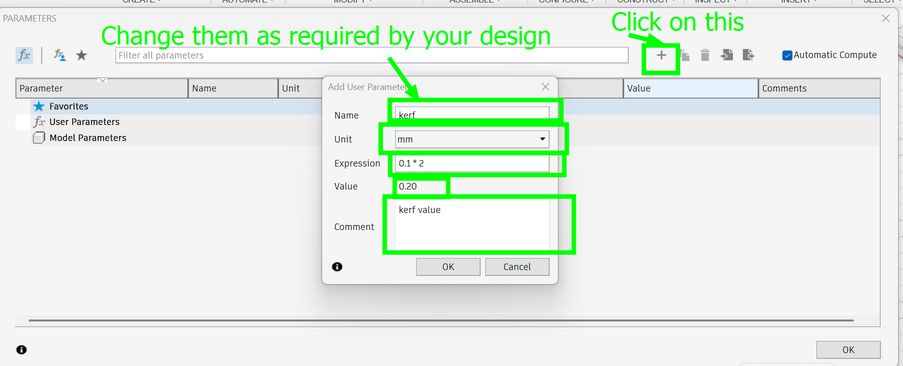
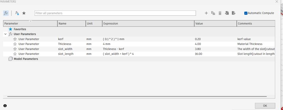
These are everything that I have added in as parameters
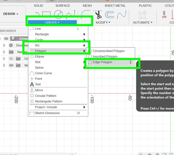
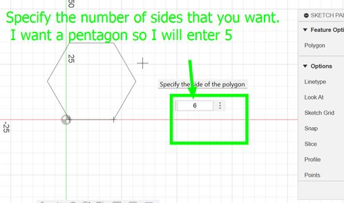
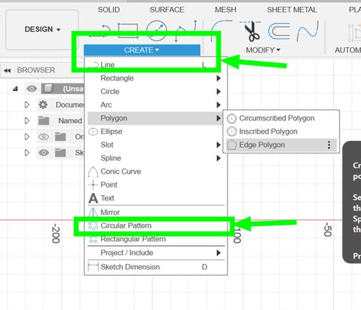
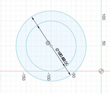
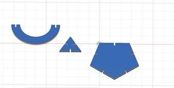
Then goto Sketch and choose a plane[I prefer x,y(top view)]. Goto Create> Polygons > Edge Polygon and then specify the number of edges that you want. I wanted to create a pentagon so I entered 5.
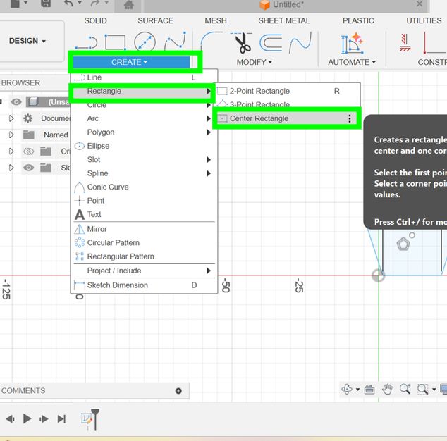
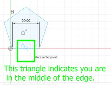
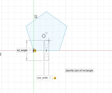
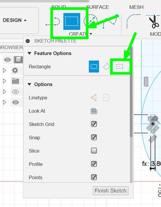
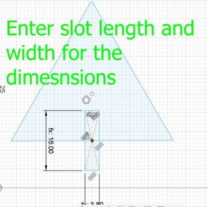
Then goto Sketch and choose Create > Rectangle > Centre Rectangle[because it is a a rectangle defined by the center point] and then if you see a triangle, it indicates that you are in the middle of that edge so click on it. Then for the width, enter slot_width and for the rectangles height, enter slot_length.
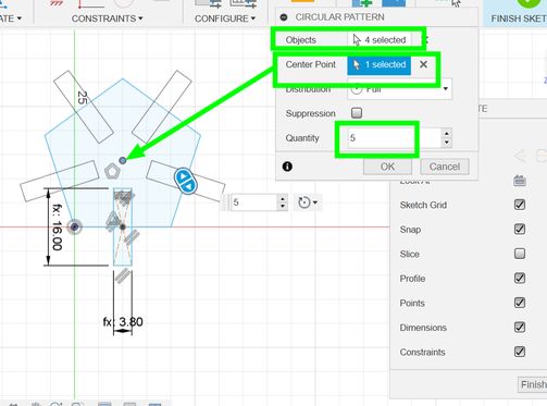
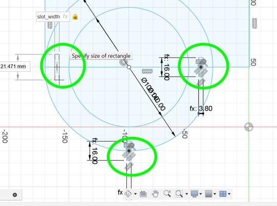
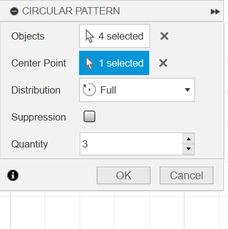
Then goto Sketch and choose Create > Circular Pattern and then select all of the edges of the centre rectangle as objects, and as for the centre point choose the centre point[dot] in the drawing, enter the quantity required and click OK.
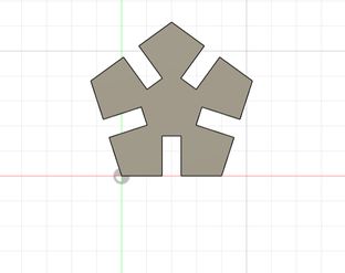
Then Extrude the shape[only the polygon]
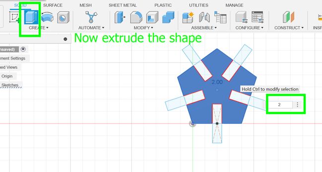
This is the result
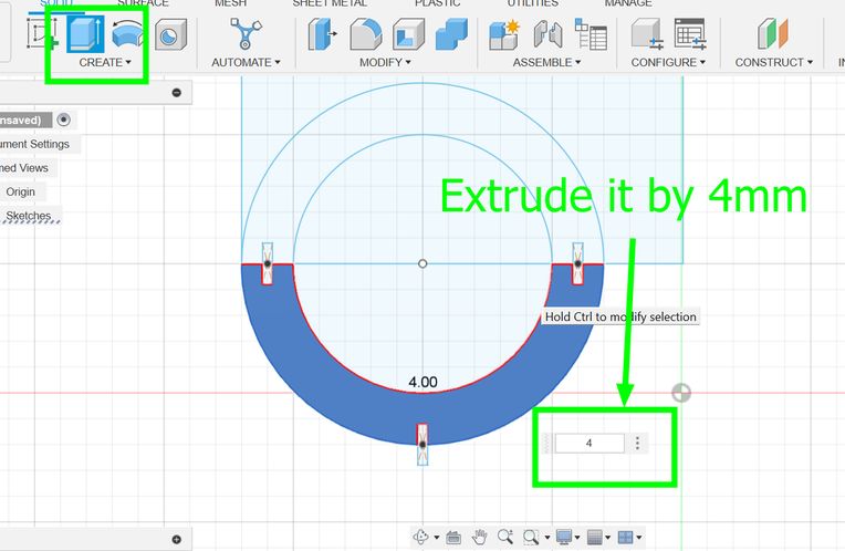
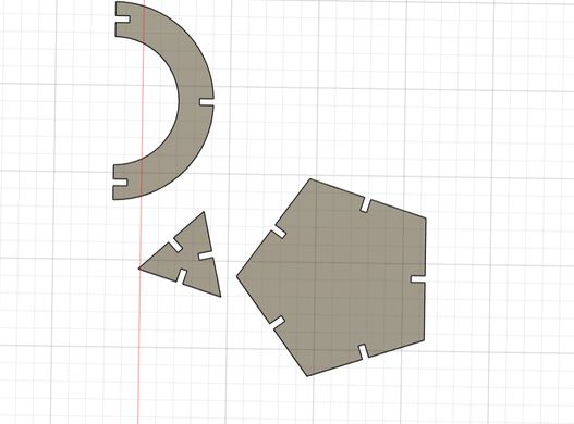
The shapes below were created using similar steps. First create a circle and create an outer circle for it
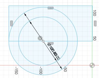
Then create a centre rectangle and set its width and height to slot_width and slot_height
Then create a slots on the centre of the following shape as shown given below. After that extrude it by 4 mm. Then create a triangle by drawing a polygon.
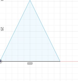
Then create a slot on the triangle and use the circular pattern as we have learned before. Create> circular pattern> select objects> select the centre point and the quantity>press ok
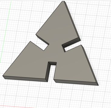
Extrude the shape and this is what my final design looks like
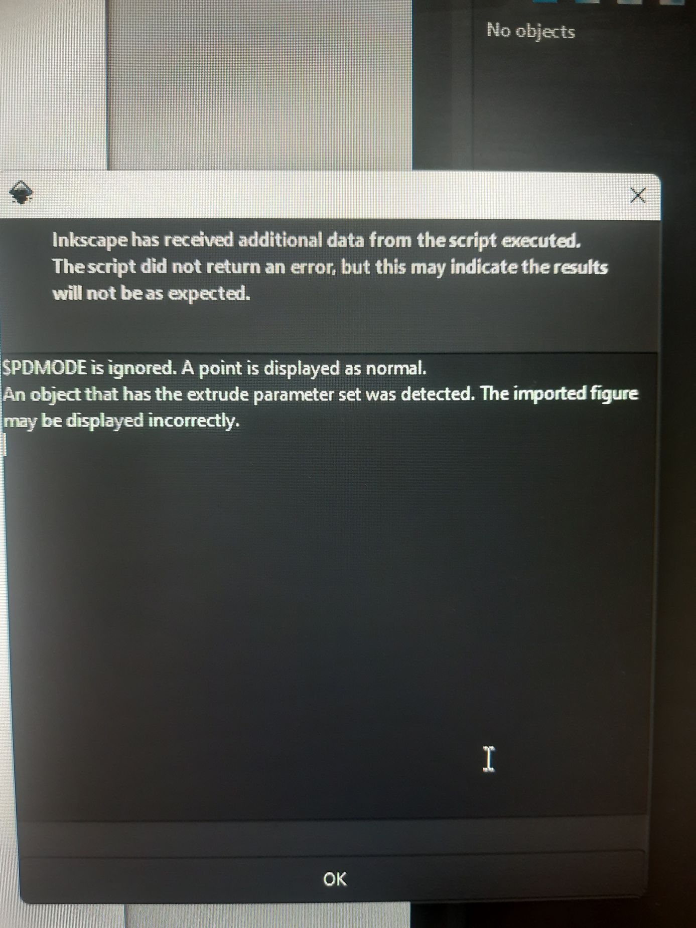
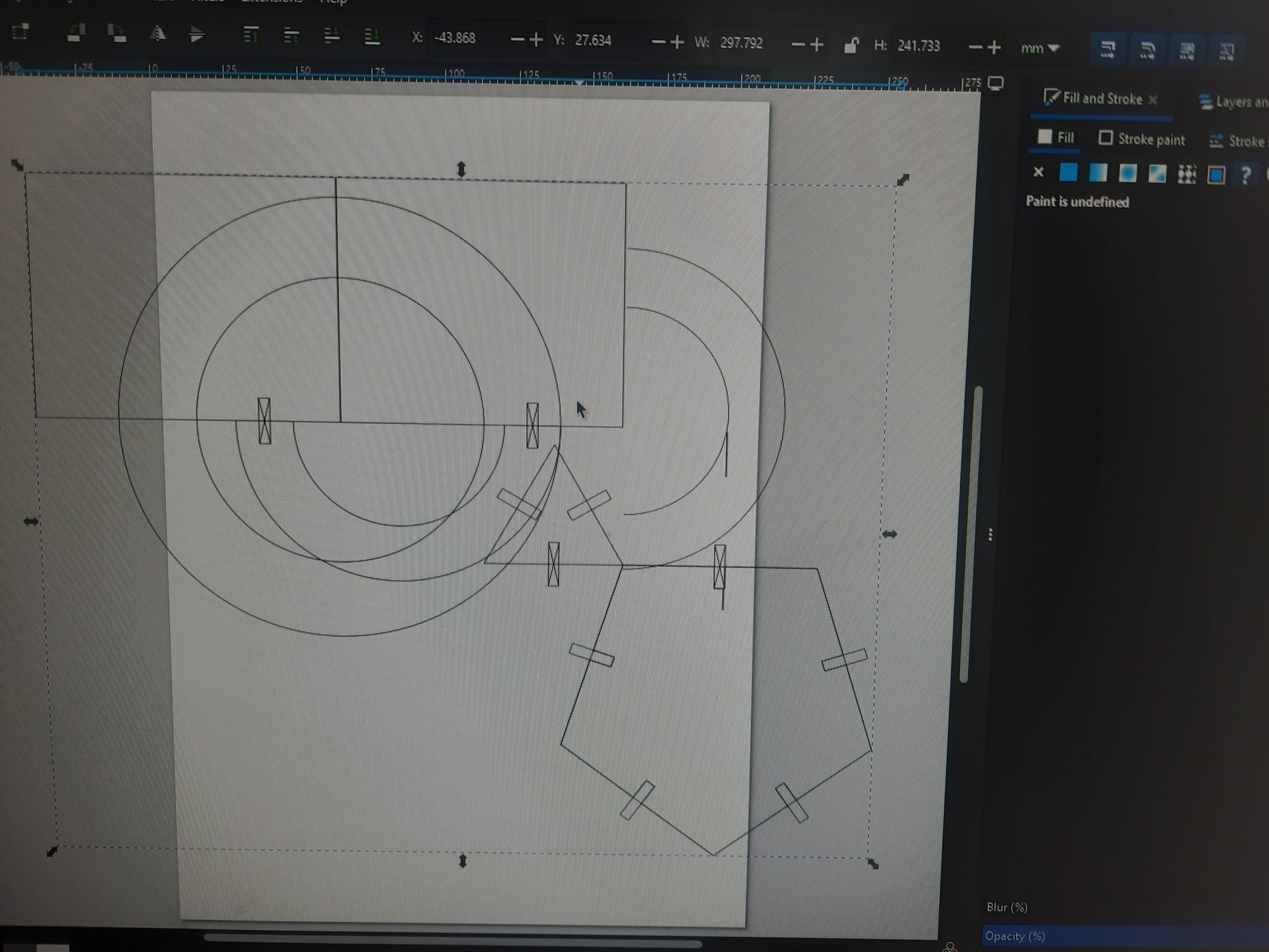
I initially tried to export the design in the form of 3D and tried to import it in inkscape which was a major disaster.
Then I decided to refer to acho Thinley Wozer's documentation on parametric design.
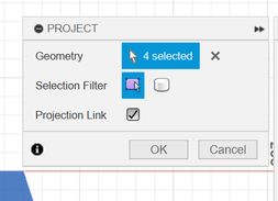
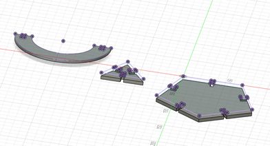
Then, I realized I needed to export my design in the form of a 2D file, so I selected the top face of the shapes that I wanted to export.
Then press P and it is projected. Just press Ok
Then, to comfirm it, you should hide the bodies using the eyeball icon on the left hand side of your pc. If you have components instead, you can hide the components too
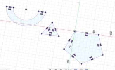
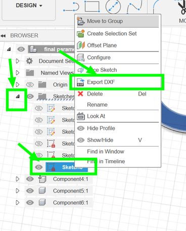
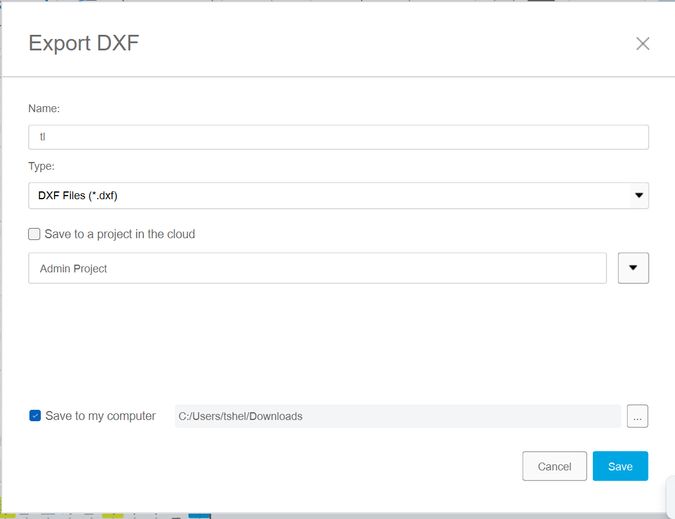
Then on your left hand side, open sketches tab, and right click on the most recent sketch (which should be your earlier projection), and the “Save As DXF” option should appear. Click on that and you should see something like this.
To set up the laser cutter for my parts, I first ensured the material (2mm cardboard) was placed flat on the honeycomb be. Then, using Inkscape, I imported my DXF file. I used auto-focus to focus the laser in the machine. For the settings, based on our group's kerf testing, I used a speed of 25 and power of 100. I made sure the vector cutting mode was selected for the outlines of my parametric pieces. Before running the full job, I did a small test cut on a scrap piece of cardboard with these settings to double-check the cut quality and it made me immensely happy seeing that it worked.
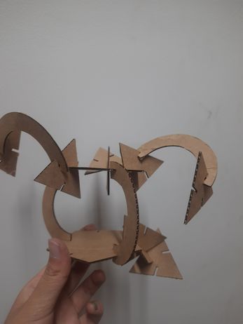
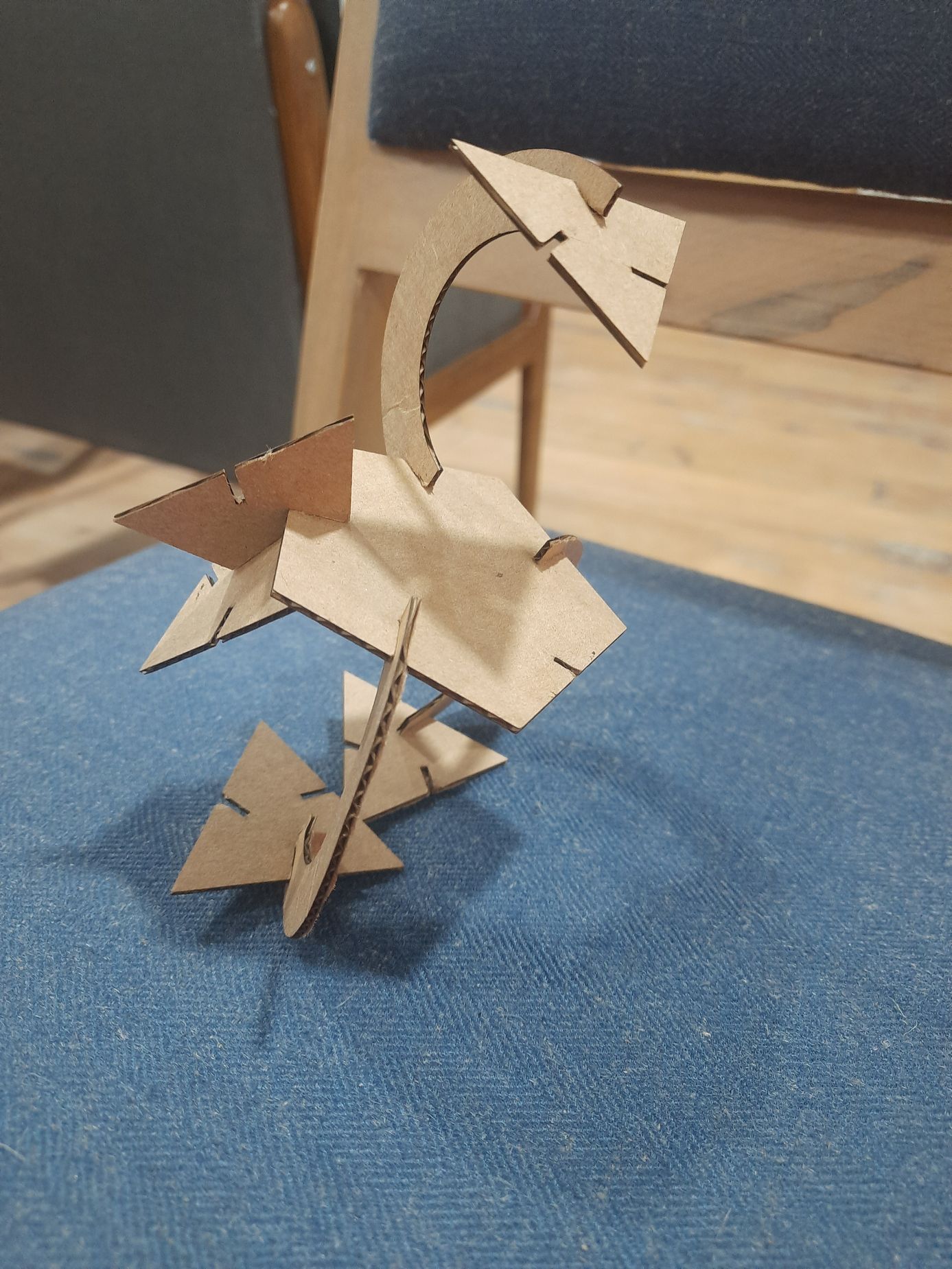
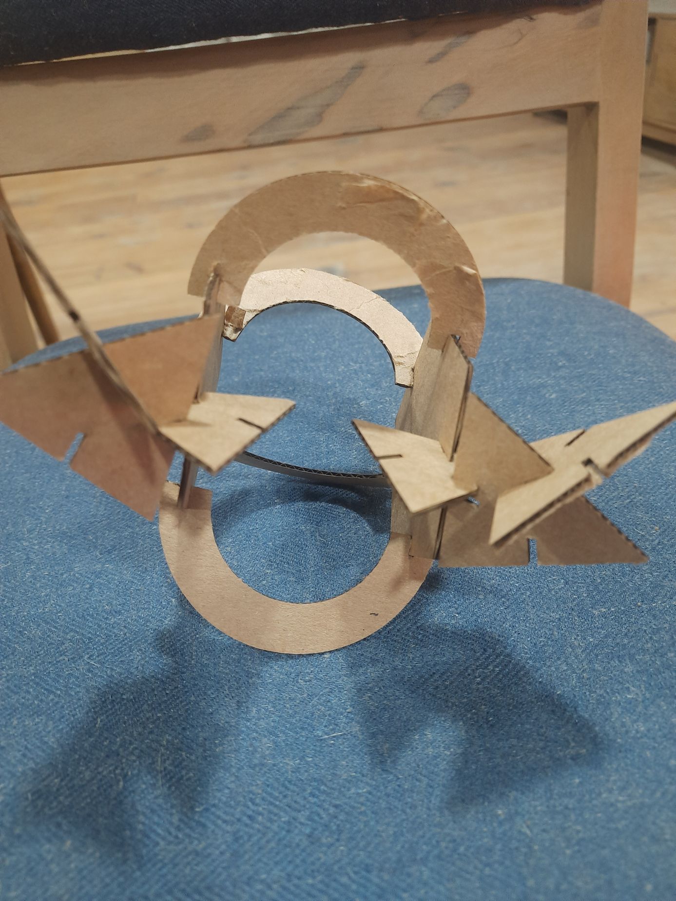
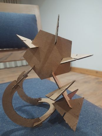
This is a video of me assembling the designs. The kerf for my parametric construction kit was accurate as the pieces fit together perfectly. The 0.15mm kerf compensation I used in my Fusion 360 design, based on our group's laser cutter characterization, resulted in joints that were neither too loose nor too tight. That was great because my designs were able to hold together.
These are some of the really cool designs I was able to make with it.
I had a lot of fun this week.
Files
You can access the files here DXF file for the parametric design f3d files for the parametric design