The LDR-MH sensor series
For the input device, we decided to try out a LDR-light dependent resistor connected via a MH sensor series. The "MH Sensor Series" refers to a line of easy-to-use sensor modules, often used in robotics and IoT projects.
These sensors are known for their simplicity and ability to provide both analog and digital outputs.
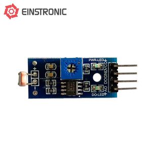
Image Source
The 4-pin LDR MH sensor module includes VCC, GND, DO (Digital Output), and AO (Analog Output) pins. It uses a voltage divider circuit made up of an LDR and a fixed resistor to convert light intensity into a changing voltage. As light falls on the LDR, its resistance decreases, altering the voltage at the junction between the LDR and the resistor—this varying voltage is sent through the AO pin.
To utilize our sensor, we tried to replicate darkness by covering it with our hands
_result.jpg)
And also by placing flashlight on it
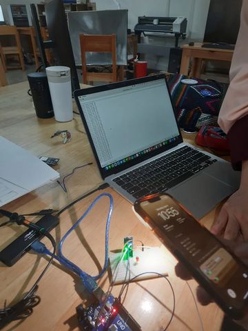
And we uploaded a code for digital output and a code for analog output.
Analog Signals
An analog signal is a continuous signal, like a smooth wave, that represents a varying quantity.
Analog signals can consist of any value within a range. For example; sound waves, and radio waves.
While observing in a oscilloscope, we see it as waveforms, providing a visual representation of their behavior over time.
This is the code that we uploaded for the sensor.
int ldrPin = A0;       // AO pin of MH LDR sensor connected to A0
int ldrValue = 0;      // Variable to store LDR value

void setup() {
  Serial.begin(9600);  // Start serial monitor
  pinMode(ldrPin, INPUT);
}

void loop() {
  ldrValue = analogRead(ldrPin);  // Read analog value from LDR
  Serial.print("Analog Reading from AO : ");
  Serial.println(ldrValue);       // Print the value to Serial Monitor

  delay(500);  // Wait for 0.5 seconds
}
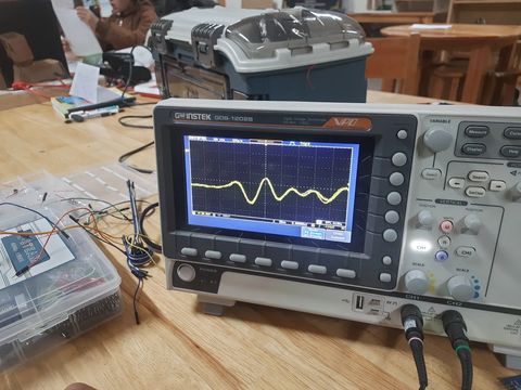
This will give a sine wave because the light intensity that the LDR is detecting is fluctuating in a sinusoidal pattern, causing the LDR's resistance (and consequently, the voltage at the analog output) to vary in a similar sine-wave manner.
Digital Signals
A digital signal is a representation of data as a sequence of discrete values, typically represented as 0s and 1s, known as binary digits or bits.
For example; smart watches, and digital clocks.
While observing in a oscilloscope, we see it as waveforms, providing a visual representation of their behavior over time.
This is the code that we uploaded for the sensor.
int ldrDigitalPin = 2;  // DO pin of MH LDR sensor connected to D2
int ldrState = 0;       // Variable to store digital state

void setup() {
  pinMode(ldrDigitalPin, INPUT);
  Serial.begin(9600);
}

void loop() {
  ldrState = digitalRead(ldrDigitalPin);  // Read digital output

  if (ldrState == HIGH) {
    Serial.println("Bright Light Detected");
  } else {
    Serial.println("Darkness Detected");
  }

  delay(500);  // Wait half a second
}
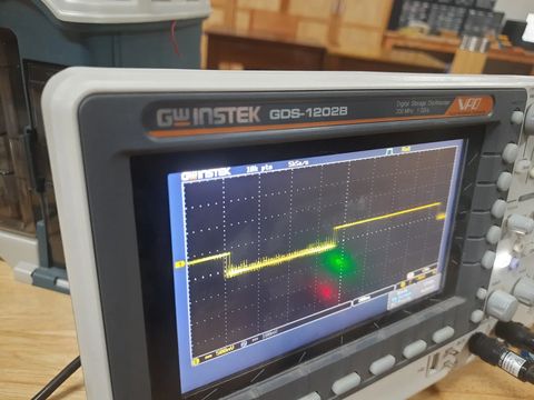
This will give a square wave because the DO pin is simply a binary signal where the voltage alternates between two levels: HIGH (typically 5V) and LOW (typically 0V). This happens in response to the light level—if it's bright enough (above the threshold), the signal will be HIGH, and if it's too dark (below the threshold), the signal will be LOW. This rapid switching between HIGH and LOW creates a square wave pattern.
While square waves are the most common waveform you’ll see from digital signals, it's not always the case. The appearance of the waveform depends on the design and function of the digital system. Pulse waves, noise, and modulated signals can also cause digital signals to look different from simple square waves. If the signal is being modulated or there’s interference, you could see waveforms that don't resemble traditional square waves at all.
Reflection
Working with the LDR-MH sensor module gave me a clearer understanding of the differences between analog and digital signals in practical terms. I was particularly fascinated by how the sensor could provide two types of outputs based on the same input (light). By observing the values on the Serial Monitor and noticing how they changed when we blocked or shone light on the sensor, I could see how analog signals represent gradual change while digital signals are more about threshold-based detection. Uploading and testing both codes helped me build confidence in reading sensor data and interpreting what it means in real-world conditions. One small challenge was distinguishing how the digital output responded—it took a few trials to understand the preset threshold that decides between HIGH and LOW.