Group Assignment
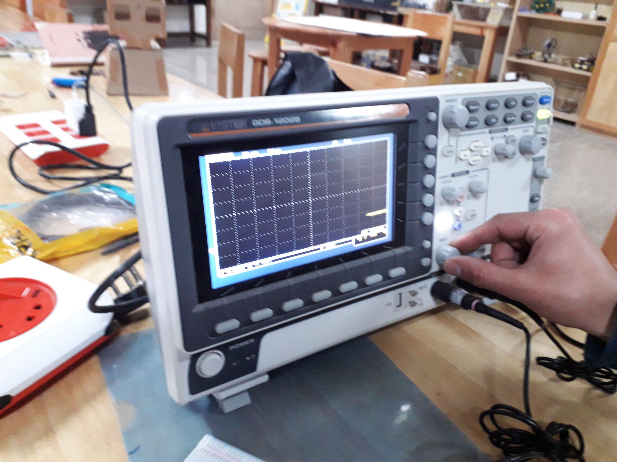
The oscilloscope is an instrument that graphically displays electrical signals and shows how those signals change over time. The oscilloscope that we have at our local Fab Lab is the GDS-1202B GW INSTEK. It’s equipped with a lot of buttons and functions to visualize and analyze waveforms. Here are some of the key buttons and their functions:
- Identify Connection Points:
- Find the signal pin on the microcontroller.
- Locate the GND pin for reference.
- Connect Oscilloscope Probes:
- Attach the probe tip to the signal pin.
- Connect the ground clip to the GND pin.
- Configure the Oscilloscope:
- Set voltage scale (e.g., 1V/div).
- Adjust time base for signal frequency.
- Set trigger mode (Auto/Normal).
- Power On the Microcontroller:
- Ensure proper power supply before measurement.
- Observe and Analyze:
- Check waveform characteristics.
- Adjust settings for better visibility.
Mutimetre
A multimeter is a tool used to measure electrical properties like voltage (V), current (A), and resistance (Ω). It helps troubleshoot circuits, check battery levels, and test components. Image Source
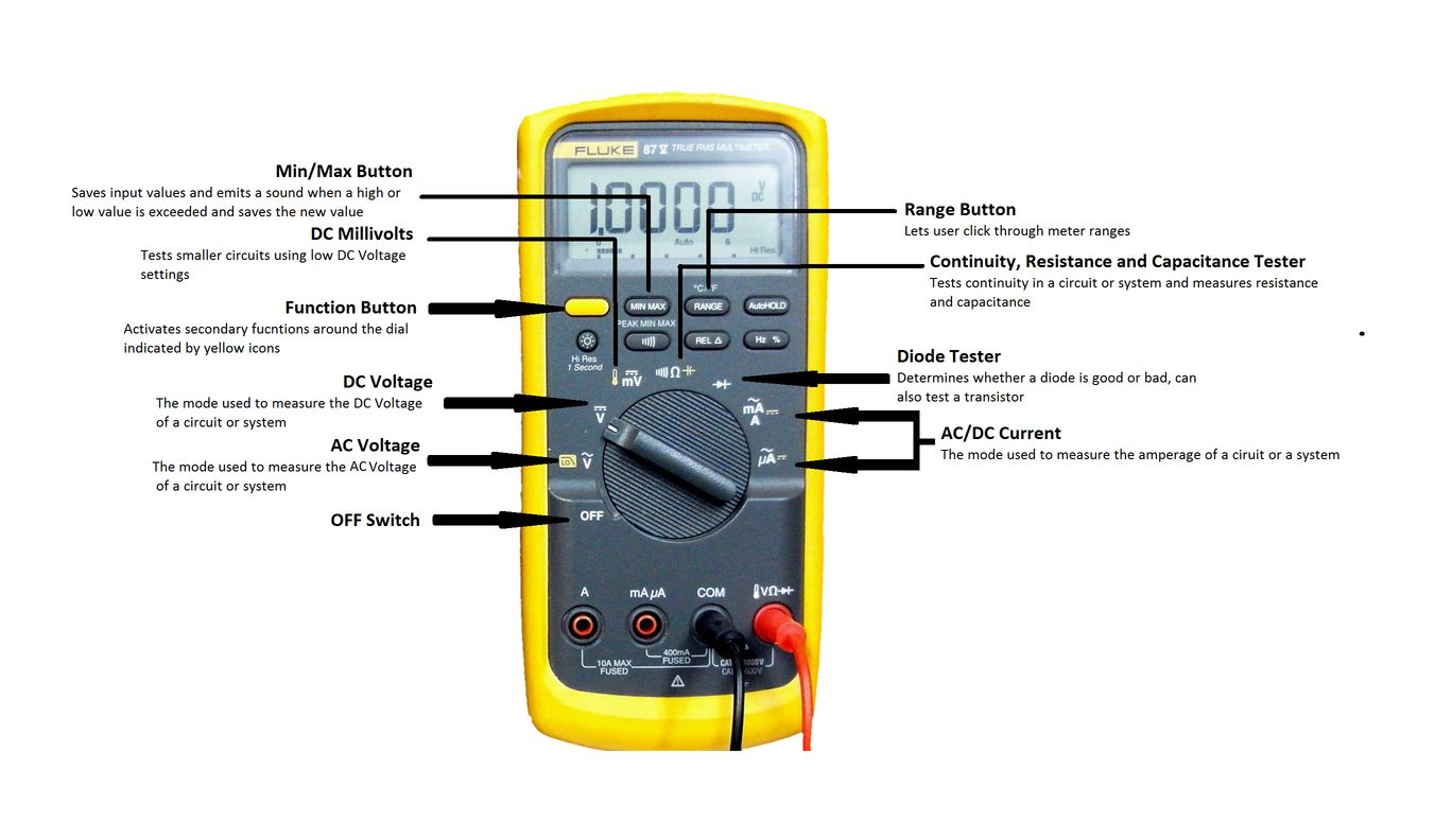
- Multimetre functions:
- Voltage Measurement: Checks DC (batteries, circuits) and AC (wall outlets).
- Current Measurement: Measures the flow of electricity.
- Resistance Measurement: Tests resistors and wire continuity.
- Continuity Test: Beeps if a circuit is complete.
- Diode Test: Checks if a diode is working.
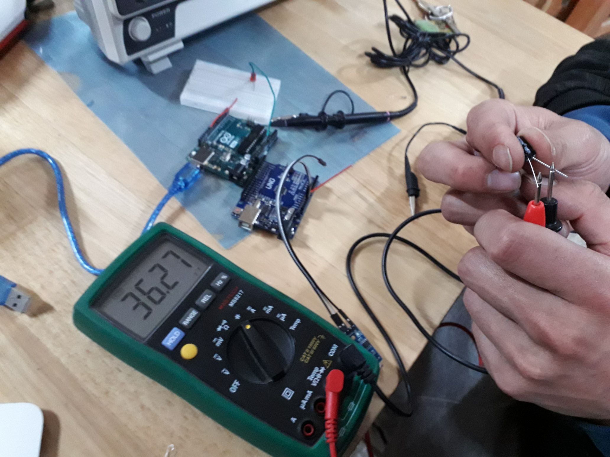
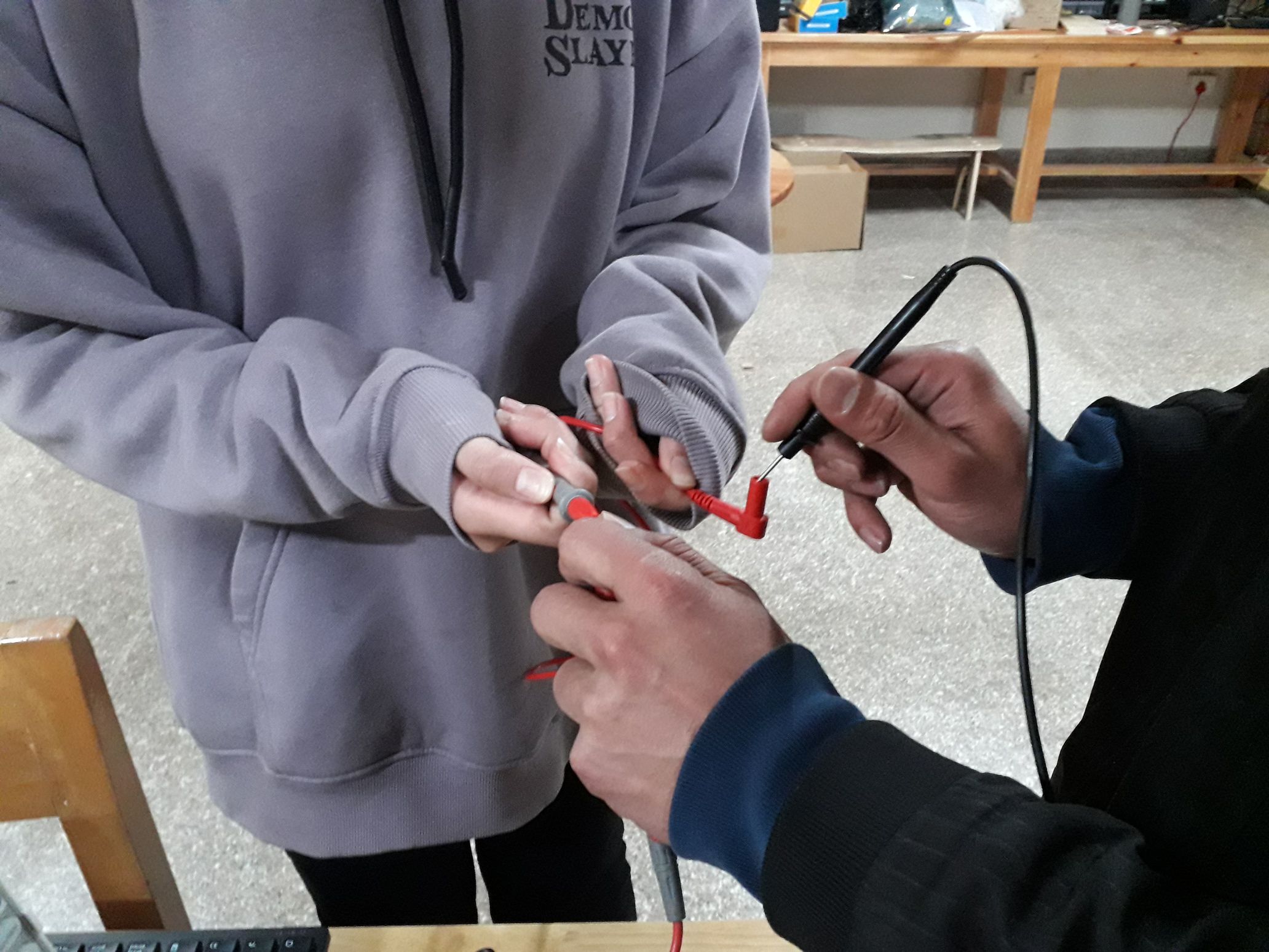
A continuity test checks if there is a complete electrical path between two points in a circuit. It helps detect broken traces, faulty connections, and short circuits.
- Identify Connection Points:
- Turn the dial to the continuity mode (symbol: sound waves or diode symbol).
- Connect Oscilloscope Probes:
- Touch one probe to one end of the connection.
- Touch the other probe to the other end.
- Understanding the results:
- If you hear a beep (or see a low resistance value), continuity exists. ✅
- If no beep (or high resistance), the connection is broken. ❌.
- Check for Short Circuits:
- If unintended paths show continuity, look for solder bridges or faulty wiring.
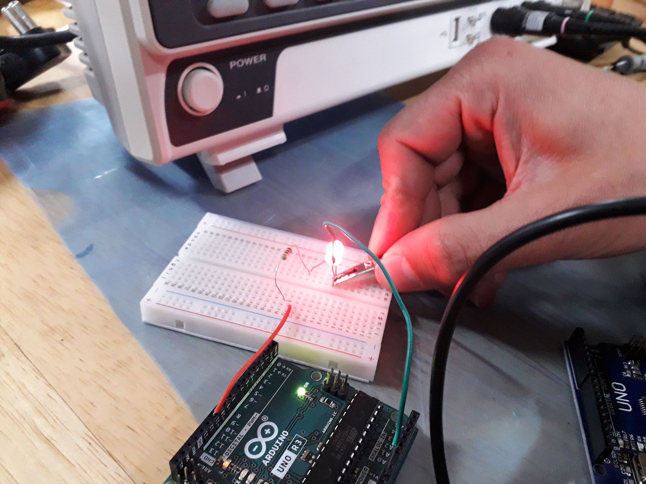
Before using the oscilloscope, we first built a simple LED circuit using an Arduino Uno, breadboard, resistor, and power supply to understand how digital signals control an LED.
- Wiring on the Breadboard:
- Insert the LED into the breadboard.
- Connect the anode (+) of the LED to an Arduino digital pin through a resistor.
- Connect the cathode (-) of the LED to GND.
- Upload a blink code to make the LED turn ON and OFF.
- Place the oscilloscope probe on the Arduino output pin.
- Attach the ground clip to the breadboard’s GND rail.
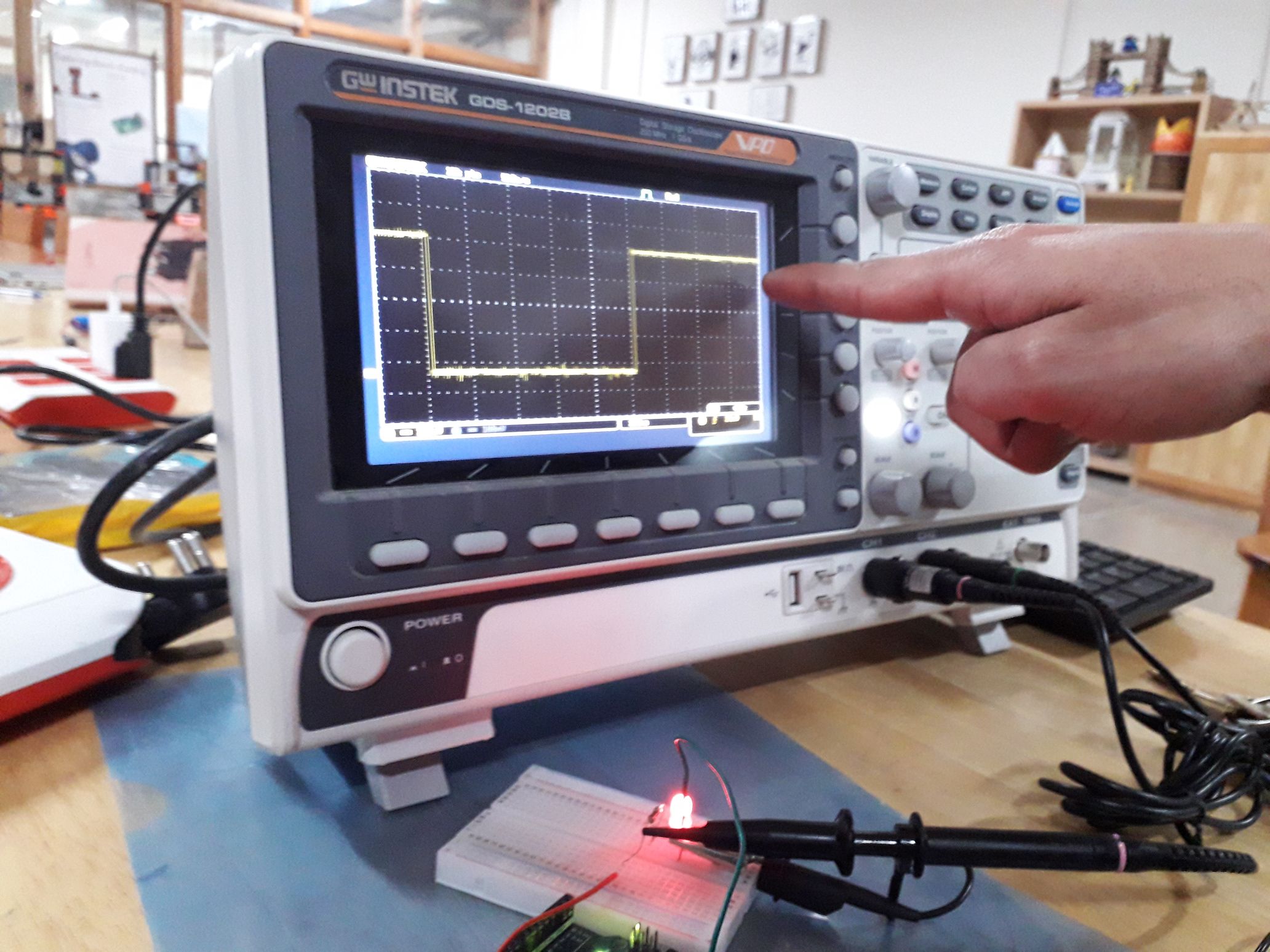
- After setting up the onscilloscope, observe the digital signal:
- When LED is ON: The oscilloscope shows high voltage (e.g., 3.3V or 5V).
- When LED is OFF: The oscilloscope shows low voltage (0V).
- If the LED blinks, a square wave appears on the screen, where:
- High duration = LED ON
- Low duration = LED OFF
Reflection
This week’s group assignment was really fun and super helpful. Getting to use the oscilloscope and multimetre and actually see the signals change in real-time made circuits feel way more real instead of just something we learn about in class. It was cool to realize that everything happening in a circuit isn’t just random—it’s all calculated, even if it sometimes feels like magic.
Huge thanks to Mr.Anith Ghalley, Yangtshel Wangyel and Dawa Seldon for helping us learn about it!!!