Networking and communications
- Design, build, and connect wired or wireless node(s) with network or bus addresses and local input &/or output device(s)
In group assignment, we use 2 XIAO ESP32C3 and ESP-NOW protocol to connect the joystick as remote to control of stepper motor. In my final project, I want to use a remote with buttons to send singal to the main game board, so in the individual part, I'll keep using the ESP-NOW protocol as a remote method to connect 2 XIAO ESP32C3 board.
ESP-NOW
Tutorials for ESP-NOW: https://randomnerdtutorials.com/esp-now-esp32-arduino-ide/
ESP-NOW is a protocol developed by Espressif, which enables multiple devices to communicate with one another without using Wi-Fi.
The ESP-NOW can be connected in can connect to the control board in many different ways:
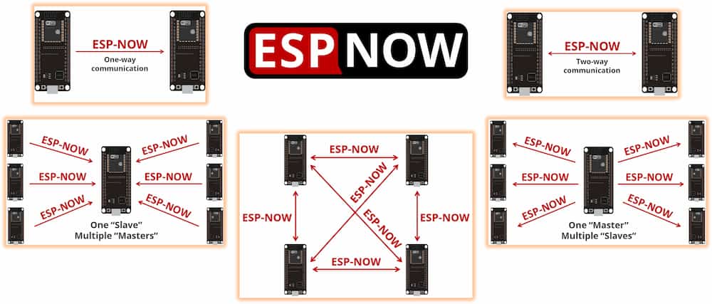
In the final project, I need a basic a one-way communication, so I will start will a basic one-way communication sample.
Connection
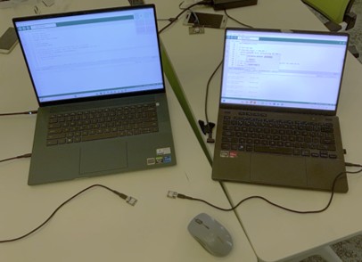
First I use a simple ESP-NOW example for testing. It requied two ESP32 board, one for sender and one for receiver.
It can be done by using one computer, but you need to change the upload port while uploading the program to the different board.
For easier editing and uploading, I choose to use two computers and connect one of XIAO ESP32C3 to each of them.
Getting MAC address
To communicate via ESP-NOW, you need to know the MAC Address of the ESP32 receiver. That’s how you know to which device you’ll send the data to.
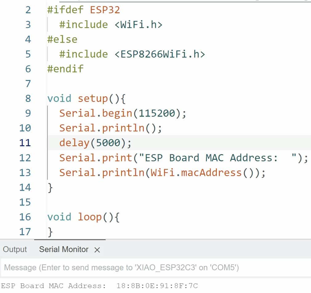
To find out the MAC address of the development board, use the following code:
Code
#ifdef ESP32
  #include <WiFi.h>
#else
  #include <ESP8266WiFi.h>
#endif

void setup(){
  Serial.begin(115200);
  Serial.println();
  delay(5000);
  Serial.print("ESP Board MAC Address:  ");
  Serial.println(WiFi.macAddress());
}

void loop(){
}
After the test, the MAC address of my XIAO ESP32C3 is 18:8B:0E:91:8F:7C.
For backup exchange, I also test the MAC address of another two backup XIAO ESP32C3. There address are E4:B3:23:C4:54:04and B0:81:84:04:4A:64.
Set a new MAC address
We can also customize a temporary MAC address for the ESP32 board, but this temporary address will not overwrite the original address.
Tutorials: https://lingshunlab.com/book/esp32/esp32-mac-address-get-and-set
Code
#include <WiFi.h>
#include <esp_wifi.h>

// Set your new MAC Address
uint8_t newMACAddress[] = {0xAA, 0xBB, 0xCC, 0x11, 0x22, 0x33};

void setup(){
  Serial.begin(115200);
  Serial.println();

  WiFi.mode(WIFI_STA); //st WIFI mode to WIFI_STA

  Serial.print("[OLD] ESP32 Board MAC Address:  ");
  Serial.println(WiFi.macAddress());
  // ESP32 Board add-on before version < 1.0.5
  //esp_wifi_set_mac(ESP_IF_WIFI_STA, &newMACAddress[0]);
  // ESP32 Board add-on after version > 1.0.5
  esp_wifi_set_mac(WIFI_IF_STA, &newMACAddress[0]); // set the new address
  Serial.print("[NEW] ESP32 Board MAC Address:  ");
  Serial.println(WiFi.macAddress());
}

void loop(){
}
In the example above, the temporary MAC address will be AA:BB:CC:11:22:33. Every time the power is off or restarted, the board's address will be restored to the original factory address. It will be helpful if a new develop board is replaced, and we don't need to know the MAC address of the new board and don't need to change the program of the sender board.
Send and receive data
First upload the following code to the sender board. Remeber to change the MAC address to the one of the receive board at line 5.
Code
#include <esp_now.h>
#include <WiFi.h>

// REPLACE WITH YOUR RECEIVER MAC Address, or change the receive address to {0xAA, 0xBB, 0xCC, 0x11, 0x22, 0x33};
uint8_t broadcastAddress[] = {0xAA, 0xBB, 0xCC, 0x11, 0x22, 0x33};
// Structure example to send data, must match the receiver structure
typedef struct struct_message {
  char a[32];
  int b;
  float c;
  bool d;
} struct_message;

// Create a struct_message called myData
struct_message myData;
esp_now_peer_info_t peerInfo;

// callback when data is sent
void OnDataSent(const uint8_t *mac_addr, esp_now_send_status_t status) {
  Serial.print("\r\nLast Packet Send Status:\t");
  Serial.println(status == ESP_NOW_SEND_SUCCESS ? "Delivery Success" : "Delivery Fail");
}

void setup() {
  Serial.begin(115200); // Init Serial Monitor
  WiFi.mode(WIFI_STA); // Set device as a Wi-Fi Station

  // Init ESP-NOW
  if (esp_now_init() != ESP_OK) {
    Serial.println("Error initializing ESP-NOW");
    return;
  }

  // Once ESPNow is successfully Init, we will register for Send CB to
  // get the status of Trasnmitted packet
  esp_now_register_send_cb(OnDataSent);

  // Register peer
  memcpy(peerInfo.peer_addr, broadcastAddress, 6);
  peerInfo.channel = 0;
  peerInfo.encrypt = false;

  // Add peer
  if (esp_now_add_peer(&peerInfo) != ESP_OK){
    Serial.println("Failed to add peer");
    return;
  }
}

void loop() {
  // Set values to send
  strcpy(myData.a, "THIS IS A CHAR");
  myData.b = random(1,20);
  myData.c = 1.2;
  myData.d = false;

  // Send message via ESP-NOW
  esp_err_t result = esp_now_send(broadcastAddress, (uint8_t *) &myData, sizeof(myData));
  if (result == ESP_OK) {
    Serial.println("Sent with success");
  }
  else {
    Serial.println("Error sending the data");
  }
  delay(2000);
}
And here is the code for the receive board. If you want to set a fix MAC address, remove the // in the 2 lines next to the line start with //*if.
Code
#include <esp_now.h>
#include <WiFi.h>

typedef struct struct_message {
    char a[32];
    int b;
    float c;
    bool d;
} struct_message;

// Create a struct_message called myData
struct_message myData;

// callback function that will be executed when data is received
void OnDataRecv(const uint8_t * mac, const uint8_t *incomingData, int len) {
  memcpy(&myData, incomingData, sizeof(myData));
  Serial.print("Bytes received: ");
  Serial.println(len);
  Serial.print("Char: ");
  Serial.println(myData.a);
  Serial.print("Int: ");
  Serial.println(myData.b);
  Serial.print("Float: ");
  Serial.println(myData.c);
  Serial.print("Bool: ");
  Serial.println(myData.d);
  Serial.println();
}

// *If you want to set the receiver a new mac address, remove the // in next line.
//uint8_t newMACAddress[] = { 0xAA, 0xBB, 0xCC, 0x11, 0x22, 0x33 };

void setup() {
  Serial.begin(115200);
  WiFi.mode(WIFI_STA);   // Set device as a Wi-Fi Station

// *If you want to set the receiver a new mac address, remove the // in next line.
// esp_wifi_set_mac(WIFI_IF_STA, &newMACAddress[0]);

  if (esp_now_init() != ESP_OK) {         // Init ESP-NOW
    Serial.println("Error initializing ESP-NOW");
    return;
  }

  // Once ESPNow is successfully Init, we will register for recv CB to
  // get recv packer info
  esp_now_register_recv_cb(esp_now_recv_cb_t(OnDataRecv));
}

void loop() {

}
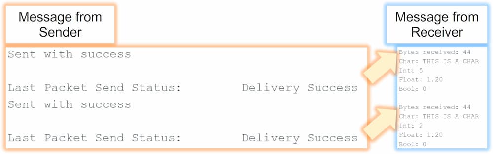
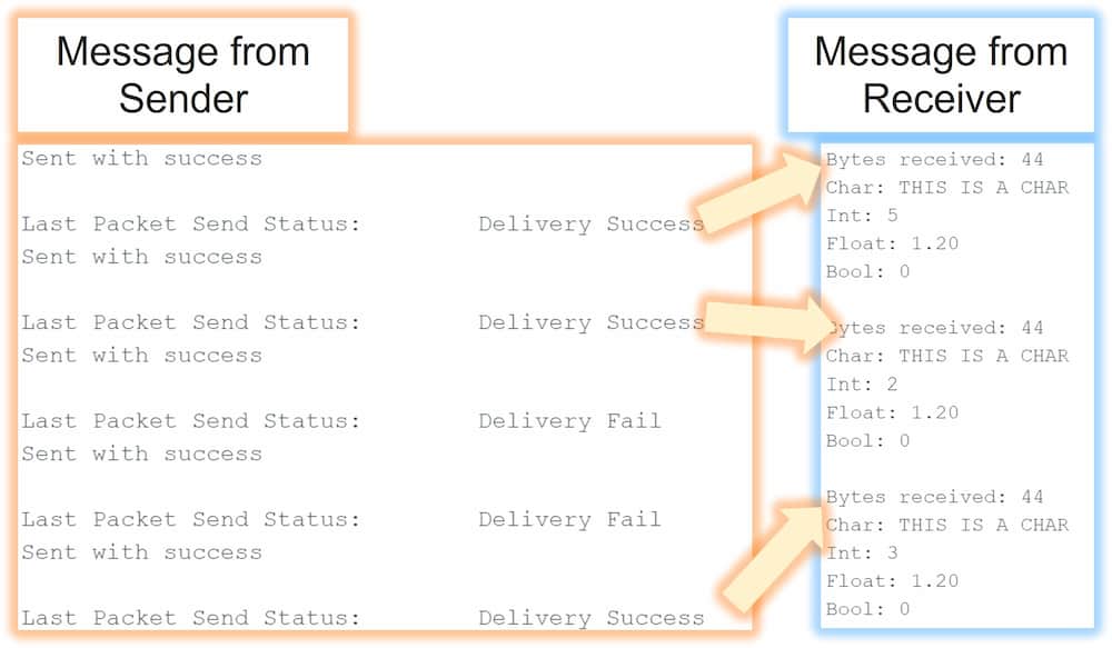
The ideal result should be like this:
In my first try, the result is like the following:
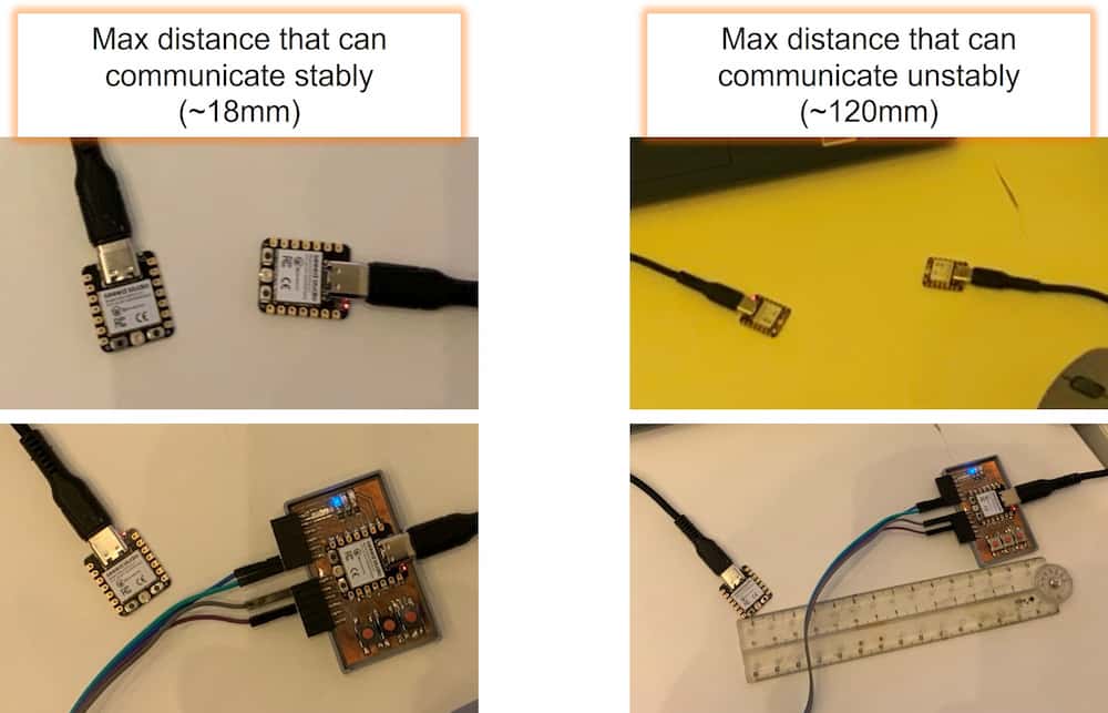
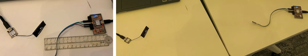
Solution
After a long time of checking, the problem is found out that the distance of the two board is the key factor. Without any extra support, the communication between the two board is effective within 18mm, and when the distance is large than about 120mm, the communction failed. The distance will be shorter when a shell is added.
Application
After the stability problem is sovled, than I try to test the function that might used in final project.
Target: Development board A as sender, with 3 buttons represent to color RGB, when the color button is pressed, the corresponding color with on as the WS2812B connected to another board B.
The sender board is the develop board product in week 8, which has 3 bulit-in buttons.
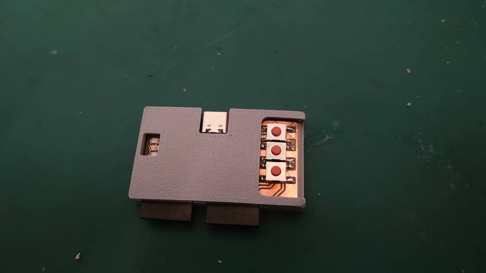
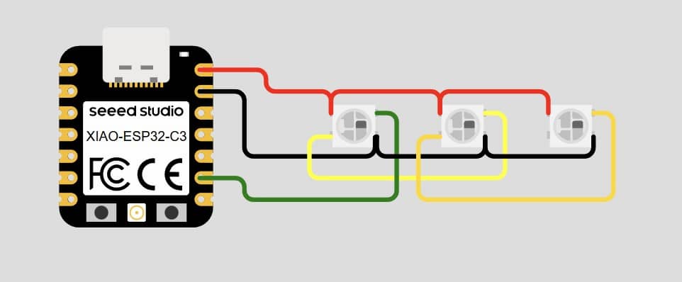
The receiver board is connected to WS2812B. The connection of WS2812B and library needed can be refer to the last part of week 10
The code for sender board
code
#include <esp_now.h>
#include <WiFi.h>

// REPLACE WITH YOUR RECEIVER MAC Address OR SET THE RECEIVER MAC Address as following:
uint8_t broadcastAddress[] = { 0xAA, 0xBB, 0xCC, 0x11, 0x22, 0x33 };

typedef struct struct_message {
  int b;
} struct_message;

struct_message myData;
esp_now_peer_info_t peerInfo;

void OnDataSent(const uint8_t *mac_addr, esp_now_send_status_t status) {
  Serial.print("\r\nLast Packet Send Status:\t");
  Serial.println(status == ESP_NOW_SEND_SUCCESS ? "Delivery Success" : "Delivery Fail");
}

void setup() {
  Serial.begin(115200);
  WiFi.mode(WIFI_STA);
  pinMode(D10, INPUT_PULLUP);  //set as INPUT_PULLUP for button
  pinMode(D9, INPUT_PULLUP);   //when pin is set as pull up, the digital read result will always be 1
  pinMode(D8, INPUT_PULLUP);

  if (esp_now_init() != ESP_OK) {    // Init ESP-NOW
    Serial.println("Error initializing ESP-NOW");
    return;
  }

  esp_now_register_send_cb(OnDataSent);
  memcpy(peerInfo.peer_addr, broadcastAddress, 6);
  peerInfo.channel = 0;
  peerInfo.encrypt = false;

  if (esp_now_add_peer(&peerInfo) != ESP_OK) {
    Serial.println("Failed to add peer");
    return;
  }
}

void loop() {
  // Set values to send
  if (digitalRead(D10) == 0 || digitalRead(D9) == 0 || digitalRead(D8) == 0) {
    delay(10);
    myData.b = (!digitalRead(D10)) * 4 + (!digitalRead(D9)) * 2 + !digitalRead(D8);
    esp_err_t result = esp_now_send(broadcastAddress, (uint8_t *)&myData, sizeof(myData));
    if (result == ESP_OK) {
      Serial.println("Sent with success");
    } else {
      Serial.println("Error sending the data");
    }
    delay(500);
  }
}
The code for receiver board
code
#include <WiFi.h>
#include <esp_wifi.h>
#include <esp_now.h>
typedef struct struct_message {
  int b;
} struct_message;
struct_message myData;

#include <Adafruit_NeoPixel.h>
#ifdef AVR
#include <avr/power.h>  // Required for 16 MHz Adafruit Trinket
#endif
#define LED_PIN D8
#define LED_COUNT 60
Adafruit_NeoPixel strip(LED_COUNT, LED_PIN, NEO_GRB + NEO_KHZ800);

int r,g,b;
int state=0;

// callback function that will be executed when data is received
void OnDataRecv(const uint8_t * mac, const uint8_t *incomingData, int len) {
 state=1;
 memcpy(&myData, incomingData, sizeof(myData));
  Serial.print("Int: ");
  Serial.println(myData.b);
}

// *If you want to set the receiver a new mac address, remove the // in next line.
uint8_t newMACAddress[] = { 0xAA, 0xBB, 0xCC, 0x11, 0x22, 0x33 };

void setup() {
  Serial.begin(115200);
  WiFi.mode(WIFI_STA);
// *If you want to set the receiver a new mac address, remove the // in next line.
 esp_wifi_set_mac(WIFI_IF_STA, &newMACAddress[0]);
  if (esp_now_init() != ESP_OK) {
    Serial.println("Error initializing ESP-NOW");
    return;
  }
  esp_now_register_recv_cb(esp_now_recv_cb_t(OnDataRecv));
  #if defined(AVR_ATtiny85) && (F_CPU == 16000000)
  clock_prescale_set(clock_div_1);
  #endif

  strip.begin();            // INITIALIZE NeoPixel strip object (REQUIRED)
  strip.show();             // Turn OFF all pixels ASAP
  strip.setBrightness(50);  // Set BRIGHTNESS to about 1/5 (max = 255)
  colorWipe(strip.Color(255,255,255), 5);
  strip.clear();
  strip.show();
}

void loop() {
  if (state==1){
  r=(myData.b>=4)*255;
  g=(myData.b%4>=2)*255;
  b=(myData.b%2)*255;
  Serial.print(r);
  Serial.print(",");
  Serial.print(g);
  Serial.print(",");
  Serial.print(b);
  Serial.println("");
  colorWipe(strip.Color(r,g,b), 5);
  strip.clear();
  strip.show();
  state=0;
  }
}

void colorWipe(uint32_t color, int wait) {
  for(int i=0; i<strip.numPixels(); i++) { // For each pixel in strip...
    strip.clear();
    strip.setPixelColor(i, color);         //  Set pixel's color (in RAM)
    strip.show();                          //  Update strip to match
    delay(wait);                           //  Pause for a moment
  }
}
The message from both board:
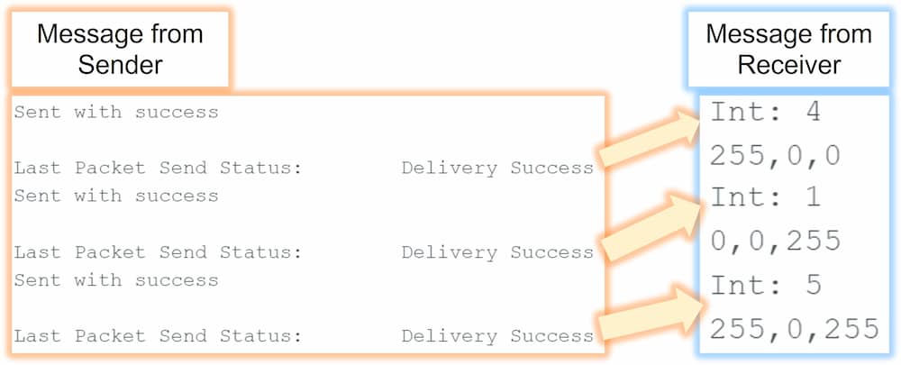
At the receiver side, the varible will be decode back to binary form, and represent the intensity of the RGB color. For example, when a varible 5 is received, it will be transform back to 101, and will be multiply by 255 as the intensity of the RGB color, show the final result will be
255,0,255, and the strip color will be purple.
The result:
The LED light is a little too shine to view directly. To make the light more comfortable to view, I turn the strip 90 degree and add another one to form a light tunnel.
ESP32 bluetooth keyboard
With the built-in Bluetooth capabilities, the ESP32 can act as a Bluetooth keyboard. This following library is needed: https://github.com/T-vK/ESP32-BLE-Keyboard
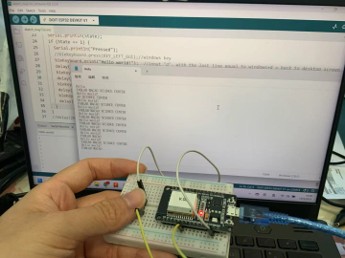
Basic test
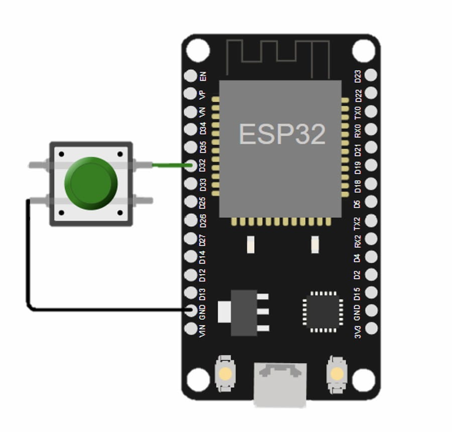
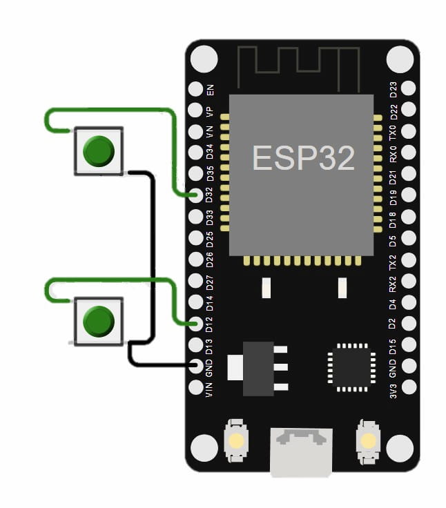
The board I used is ESP32 Devkit. For a basic sample test, I set a button, when it is pressed, the bluetooth will be sending message just like press the keyboard.
bleKeyboard.setName("xxx");, while the xxx is the name.
Code
int InputPin = 32;
int State = 0;
#include <BleKeyboard.h>
BleKeyboard bleKeyboard;

void setup() {
  Serial.begin(115200);
  pinMode(InputPin, INPUT_PULLUP);  //Not press=1
  Serial.println("Starting BLE work!");
  bleKeyboard.setName("ESPControl");  //Change the name of the ESP32
  bleKeyboard.begin();
  while (!bleKeyboard.isConnected()) {
    Serial.println("Not connected");
  }
  if (bleKeyboard.isConnected()) {
    Serial.println("Connected");
  }
  Serial.println(digitalRead(InputPin));
}

void loop() {
  State = !digitalRead(InputPin);
  Serial.println(State);
  if (State == 1) {
    Serial.println("Pressed");
    //Write the message you want to send under here, and the following code is example.
    /*bleKeyboard.print("Hello world!");
    delay(100);
    bleKeyboard.write(KEY_RETURN);
    delay(100);
    bleKeyboard.print("FABLAB MACAO SCIENCE CENTER");
    delay(100);
    bleKeyboard.write(KEY_RETURN);
    delay(100);*/
  }
}
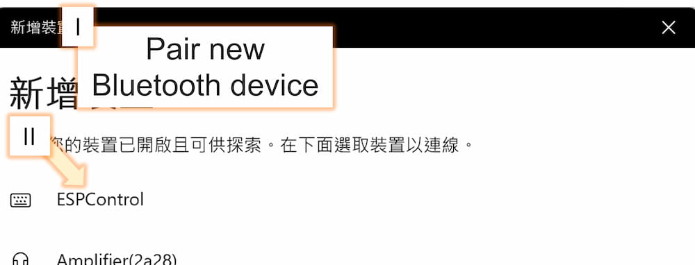
First of all, we need to pair the ESP32 to the device. I connect the ESP32 board to the computer for the first try. Confirm your device is pair to the ESP32 first.
- I. Open the bluetooth connection interface of the device
- II. Across the code above, the ESP32 name will be ESPControl. Choose it to pair.
Test for computer
The code used to print is like following:
    bleKeyboard.print("Hello world!");
    delay(100);
    bleKeyboard.write(KEY_RETURN);
    delay(100);
    bleKeyboard.print("FABLAB MACAO SCIENCE CENTER");
    delay(100);
    bleKeyboard.write(KEY_RETURN);
    delay(100);
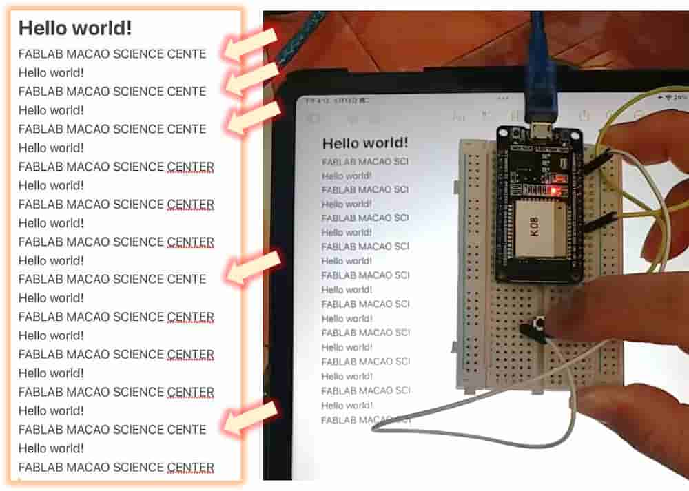
I will repeat pressing the button to send message for 10 times to see if the result is stable. The result is here:
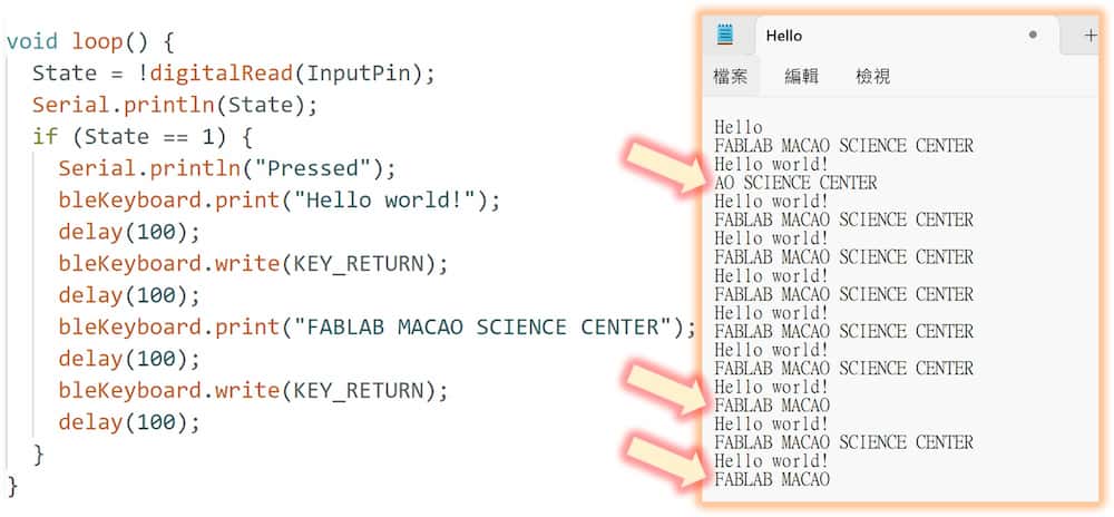
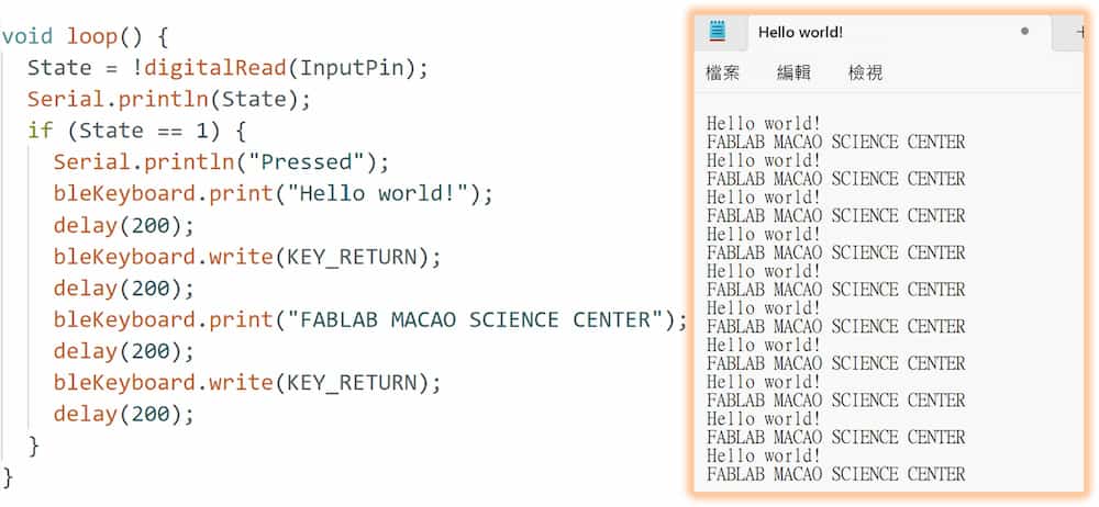
In the first try, the keyboard is work to type but the message is not show completely. It might cause by the short time for the text printing, so I retry it by increase the time in delay() from 100 to 200. After the second try, the problem sloved.
Test for ipad
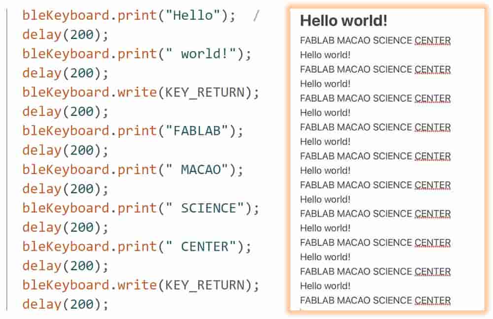
I repeat the same test on ipad, with the delay time in 200. The result is here:
Similarly to the computer test, the text isn't been shown completely. The problem is still not solved even the delay time set to 1000. So I try to divid the message into several part to make each message shorter, and it worked.
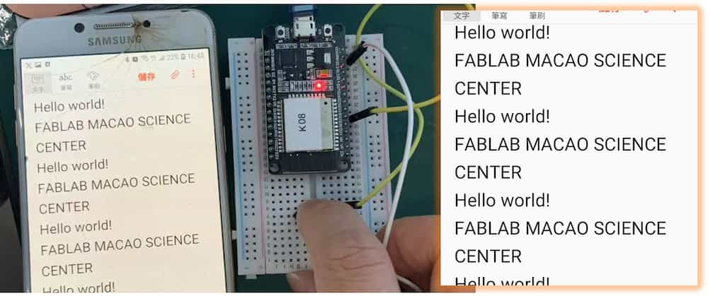
Test for smart phone
With the same code, the result work fine in the smart phone.
Problem in XIAO ESP32C3
There are problems when I use the XIAO ESP32C3 as the development board.
- I. The first type of problem is the program can't be uploaded, the IDE showing the follow message:
fatal error occurred: No serial data received. Failed uploading: uploading error: exit status 2Suggestion 1: holding B (boot) Button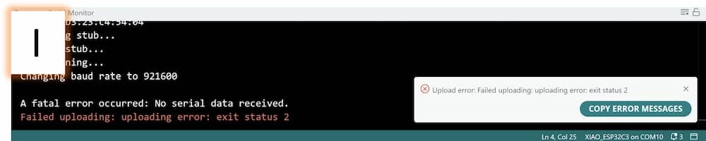
Suggestion 2: Press the B (boot) button and R (reset)
Suggestion 3: rasing all flash
Both solution is work just some time but not every time. - II. Even sometimes the program can be uploaded to the XIAO board, there still another problem. Although the devices can find the board, but it keep show the
connectingmessage and the XIAO board will finally disappear in the searching list.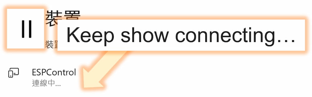
Suggestino 1: adjust the BleKeyboard.cpp file
I followed and tried to change the line 130 in the BleKeyboard.cpp file of the library as follows:
pSecurity->setAuthenticationMode(ESP_LE_AUTH_BOND);//for ESP32-C3 Protocol
but the problem is still the same.
So I recommand using other type of ESP32 board will be more stable.
Application
I want to set a short key in the computer to view the my Fab Academcy website. I also add a more button to allows me quickly switch between the last opened application(Alt + Tab).
Code
int InputPin = 32;
int InputPin2 = 12;
int State = 0;
int State2 = 0;
#include <BleKeyboard.h>
BleKeyboard bleKeyboard;

void setup() {
  Serial.begin(115200);
  pinMode(InputPin, INPUT_PULLUP);   //Not press=1
  pinMode(InputPin2, INPUT_PULLUP);  //Not press=1
  Serial.println("Starting BLE work!");
  bleKeyboard.setName("ESPControl");  //Change the name of the ESP32
  bleKeyboard.begin();
  while (!bleKeyboard.isConnected()) {
    Serial.println("Not connected");
  }
  if (bleKeyboard.isConnected()) {
    Serial.println("Connected");
  }
  Serial.println(digitalRead(InputPin2));
}

void loop() {
  State = !digitalRead(InputPin);
  State2 = !digitalRead(InputPin2);
  if (State == 1) {
    bleKeyboard.press(KEY_LEFT_GUI);  //windows key
    bleKeyboard.print("d");           //input "d", with the last line equal to windows+d = back to desktop screen
    delay(200);
    bleKeyboard.releaseAll();  //release all key pressed, like windows key
    delay(200);
    bleKeyboard.press(KEY_MEDIA_WWW_HOME);  //open default web browser
    delay(200);
    bleKeyboard.print("https://fabacademy");
    delay(200);
    bleKeyboard.print(".org/2025/labs/");
    delay(200);
    bleKeyboard.print("chaihuo/students/");
    delay(200);
    bleKeyboard.print("longwai-chan/");
    delay(200);
    bleKeyboard.write(KEY_RETURN);
  }
  if (State2 == 1) {
    bleKeyboard.press(KEY_LEFT_ALT);
    delay(200);
    bleKeyboard.press(KEY_TAB);
    delay(200);
    bleKeyboard.releaseAll();  //release all key pressed, like windows key
    delay(200);
  }
}
And here is the final result: