Week9 - Input Devices
The task of the assignment
- Measure something: add a sensor to a microcontroller board that you have designed and read it
Hardware will be used
In this assignment, XIAO ESP32C3 will be used. Seeed Studio XIAO ESP32C3 is an IoT mini development board based on the Espressif ESP32-C3 WiFi/Bluetooth dual-mode chip, featuring a 32-bit RISC-V CPU that delivers powerful computing performance with its efficient architecture. It has excellent radio frequency performance, supporting IEEE 802.11 b/g/n WiFi, and Bluetooth 5 (BLE) protocols.
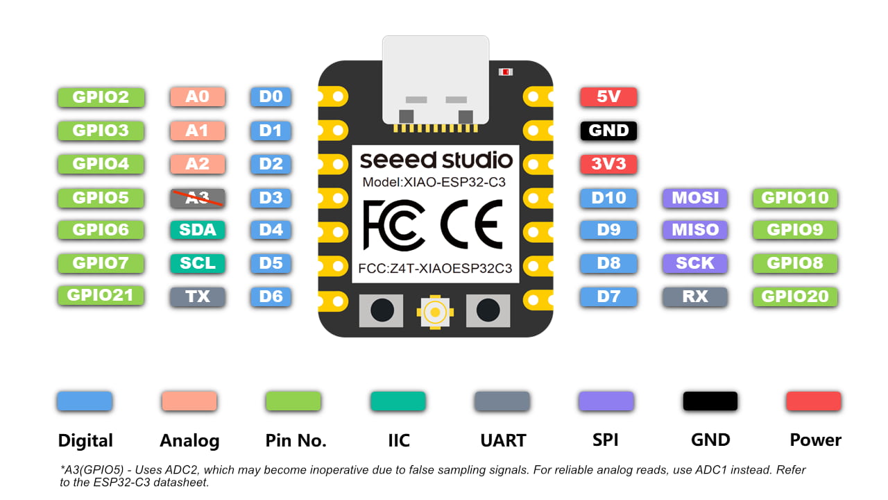
There are 10 digital IO pins, 3 analog input pins, 1 set of IIC and 1 set of SPI can be used for sensing.
There're sensing example will be describled in the following assignment.
Analog & Digital Signal
Ref: https://www.geeksforgeeks.org/difference-between-analog-and-digital-signal/
What's Digital Signal?
Digital signal is a type of signal that represents data as a sequence of discrete values, typically using binary numbers, it also contain different voltage values. Unlike analog signals, which vary continuously over time, digital signals are discrete and quantized, meaning they only take on specific, distinct values.
In digital communication and computing systems, information is encoded into digital signals for transmission, processing, and storage. These signals are commonly used in telecommunications, audio and video processing, computer networks, and many other applications.
Examples: LED control, Button States
What's Analog Signal?
Analog signal is a type of signal that represents continuous data using a continuous range of values. In other words, it can take on any value within a certain range. Analog signals are characterized by their smooth and continuous nature.
For example, imagine a sound wave. In analog form, the sound wave is represented by a continuously varying electrical signal that mirrors the fluctuations in air pressure caused by the sound.
Examples: Light Signal, Sound Attitude Signal
Comparing with Analog & Digital
| Basis | Analog Signal | Digital Signal |
|---|---|---|
| Definition | Analog signals represent continuous variations in magnitude over time. | Digital signals are Discrete and quantized, with specific values. |
| Signal Type | Continuous waveforms | Discrete Signals |
| Processing | Requires complex processing for manipulation. | Easier to process and manipulate digitally. |
| Examples | Analog audio signals, analog radio waves, Human voice, etc. | Digital audio signals, digital data streams, computers, etc. |
| Circuit Component | Amplifiers, filters, continuous-wave oscillators | Microprocessors, binary counters, logic gates |
| Signal Values | Infinite range of values | Limited to discrete values |
Joystick Module
Joystick is usually used for game controller, toy controller, or even a big real machine such as an excavator controller.
A joystick module is composed of two potentiometers square with each other, and one push button. Therefor, it provides the following outputs:
- An analog value (from 0 to 4095) corresponding to the horizontal position (called X-coordinate)
- An analog value (from 0 to 4095) corresponding to the vertical position (called Y-coordinate)
- A digital value of a push button (HIGH or LOW)
Pinout
A joystick has 5 pins:
- GND pin: needs to be connected to GND(0V)
- VCC pin: needs to be connected to VCC(5V)
- VRX pin: outputs an analog value corresponding to the horizontal position
- VRY pin: outputs an analog value corresponding to the vertical position
- SW pin: output from push button inside the joysticks. Normally open. If we use a pull-up resistor in this pin, the SW pin will be HIGH when it is not pressed, and LOW when it is pressed.
Simulation
I built a simulation for joystick module testing.
There are 3 values output: X-coordinate(0-4095) , Y-coordinate(0-4095) and switch button (0 or 1).
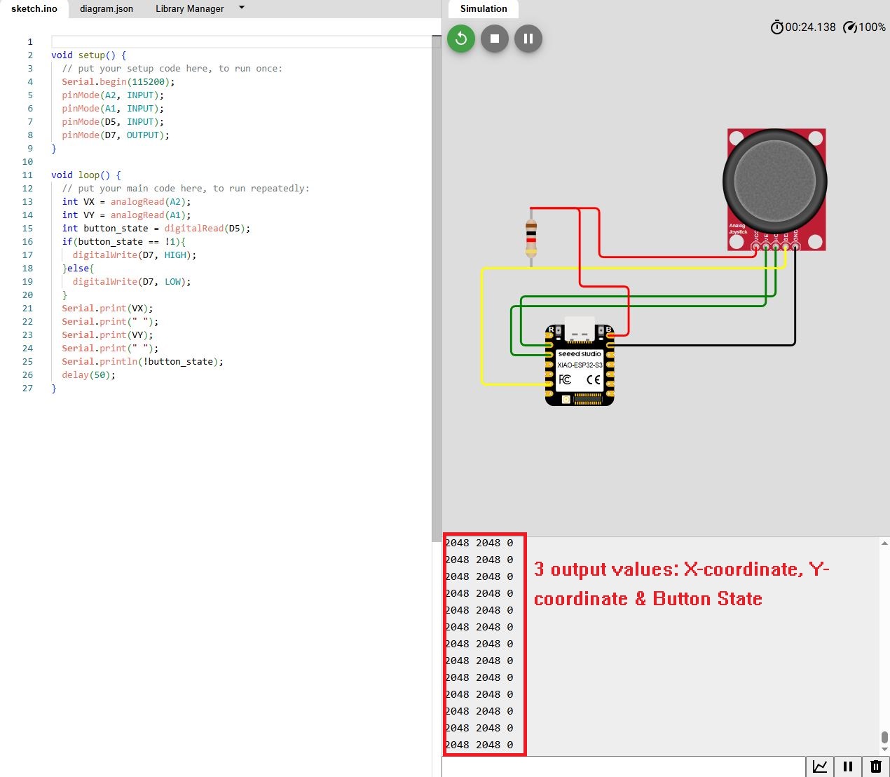
Then, I install a real circuit for testing which is controlled by PCB made in last week assignment.
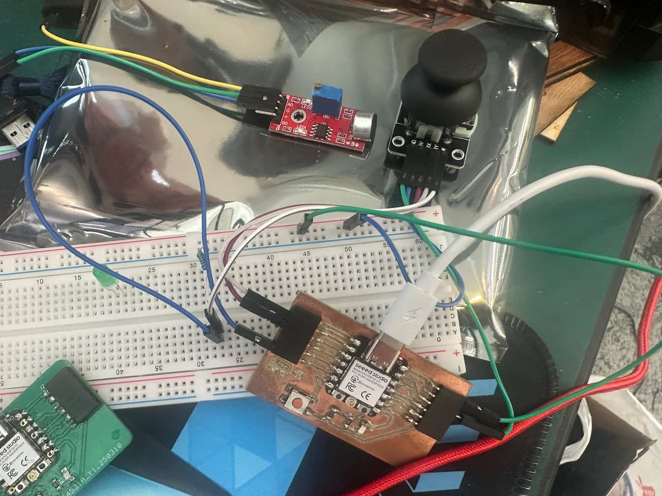
First, we test the button state and show the result by Serial Plotter of Arduino IDE.
When I press the button, the output value will be 1(HIGH). When I release the button, the output value will be 0(LOW).
Then, I test the analog signals for Vertical direction and Horizontal direction of joystick.
The blue line indicates the status of X-coordinate and red line indicates the status of Y-coordinate.
Comparing with simulation, the value of X-coordinate and Y-coordinate should be 2048 when I don't move the direction of joystick. But it's about 3400-3500 in real situation. A post-processing is essentail for normalize the variation.
Finally, I measure the change of voltage in X-coordinate change in joystick by voltmeter.
The voltage change can be seen that 2.34V to 4.97V when I pull the joystick in x direction.
Photodetector
Ref: https://esp32io.com/tutorials/esp32-ldr-module
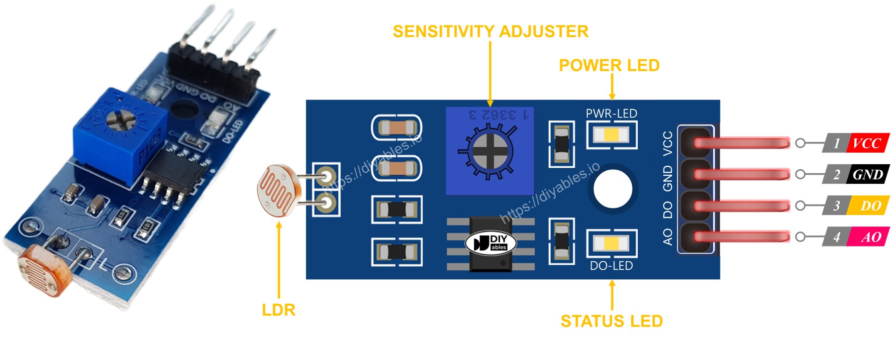
Photodetector is a photoresistor (Light Dependent Resistor). It can be used to detect the presence of the light. It can be also be used to measure the illuminance/brightness level of the light.
Pinout
The photodetector has four pins:
- VCC: Connect this pin to power source (between 3.3V - 5V)
- GND: Connect this pin to ground (0V)
- DO: This is a digital output pin. It gives a HIGH signal when it's dark and LOW when it's light. The threshold can be adjusted between dark and light using a built-in potentiometer.
- AO: This is an analog output pin. The value decreases as the light gets brighter and increases as the light gets darker.
Simulation
I built a simulation for photodetector testing. In this case I measure the analog output signal only.
In this simulation, I tested the analog signal in different environment light - light or dark.
A high analog output signal is measured when the illumination of environment is low (Dark).
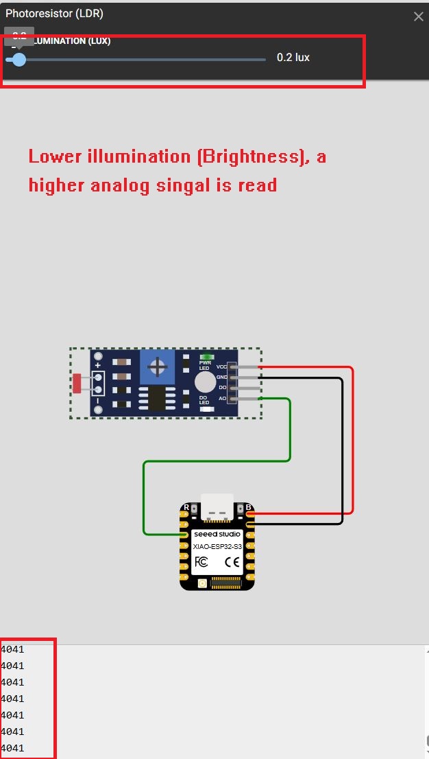
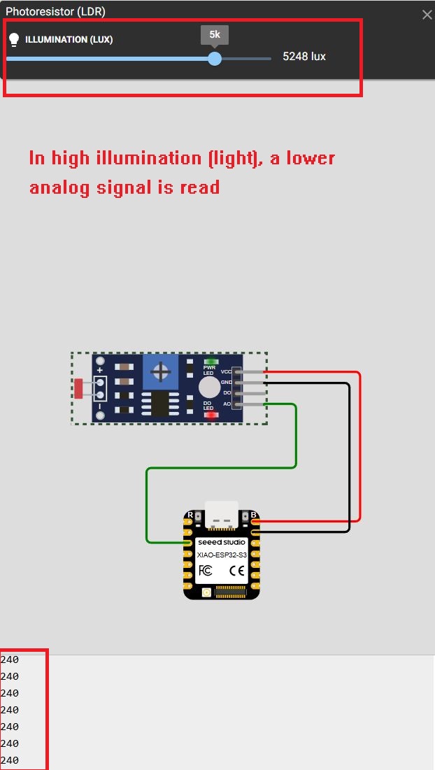
Finally, I measure the analog output of the photodetector by a real sensor.
void setup() {
  // put your setup code here, to run once:
  Serial.begin(115200);
  pinMode(A2, INPUT);
}

void loop() {
  // put your main code here, to run repeatedly:
  int sound_read = analogRead(A2);
  Serial.println(sound_read);
  delay(100);
}
Location Sensing (UART)
UART Serial communication
According to theorycircuit.com, I learnt UART serial communication.
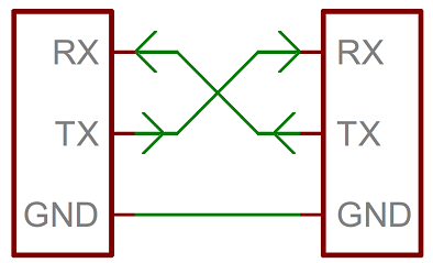
Serial Communication between microcontrollers allows to Transmit (Tx) and Receive (Rx) data in single bit sequence and have start bit in front and stop bit at the end of every eight bit (1 byte) data. Transferring data without any clock base is called as Asynchronous. The Receiver knows the data starting and ending by using the Start, Stop bits and also have some idle bits for spacing between data.
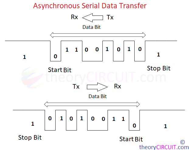
For UART serial communication, Sender (Tx) Microcontroller and Receiver (Rx) Microcontroller must have common speed for data flow which is known as the baud rate. You can program and change the speed (for both) depends on your need but for the basic setup it will be 9600.

UART can Transmit (Tx) and Receive (Rx) at the same time because it uses two independent lines but to avoid data corruption and timing issues UART is used to either send or receive at a given time and vice versa.
BDS Module
Our FABLAB is also one of the BeiDou Science Popularization Lab, a BeiDou position module will be used in ESP32C3 for getting the position.
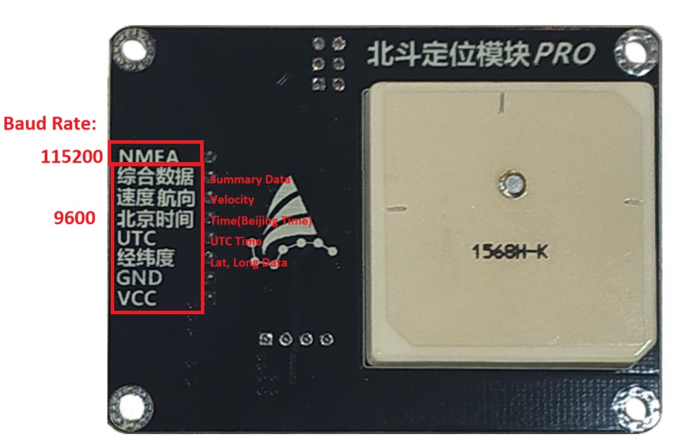
This is one of the module for positioning. Like the GPS/GNSS module, it communicate with ESP32C3 with UART Serial communication.
There are lots of data type it can output:
- NMEA Messaging Protocol
- Summary Data of Positioning (Time, Date, Latitude, Longitude, etc)
- Beijing Time
- UTC Time
- Latitude, Longitude
In a general GPS/GNSS module, we can get the position information by receiving the data in NMEA protocol. A complicated post-processing step is needed to extract essential information from the NMEA message. This module can provides extracted information. We can get the extracted information by using different pins of the module.
As ESP32C3 communicate with this module by UART communication, Baud Rate setting is a essential step. 115200bits/s is set when I want to get NMEA message. 9600 bits/s is set when I want to get the extracted information such as latitude/longitude information only.
The wiring diagram is shown as below.
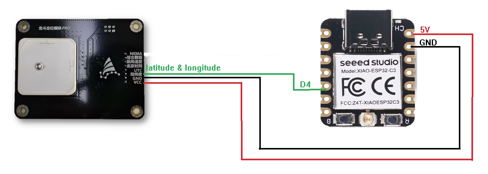
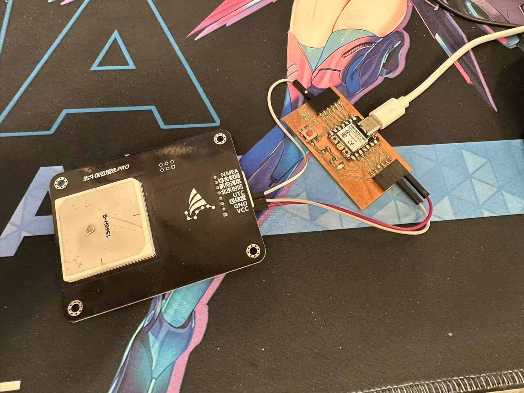
There are too many pins on the BDS Antennia module. In this assignment, I will just getting the information of positioning(latitude and longitude).
The communication protocol between the module and ESP32C2 is UART, and there's no other serial RX pin at the XIAO ESP32C2. I setup a software serial at D4 and D3 as RX2 and TX2, respectively.
#include <SoftwareSerial.h>
SoftwareSerial MySerial(D4, D3);

void setup() {
  // put your setup code here, to run once:
  Serial.begin(115200);
  MySerial.begin(9600); //Set 9600 baud rate to get the latitude/longitude information only.

}

void loop() {
  // put your main code here, to run repeatedly:
  if(MySerial.available()!=0){
      String NMEA_BD = String(MySerial.readStringUntil('\n'));
      Serial.println(NMEA_BD);
  }
}
I can receive the position information (Latitude/Longitude) from the Antennia module.
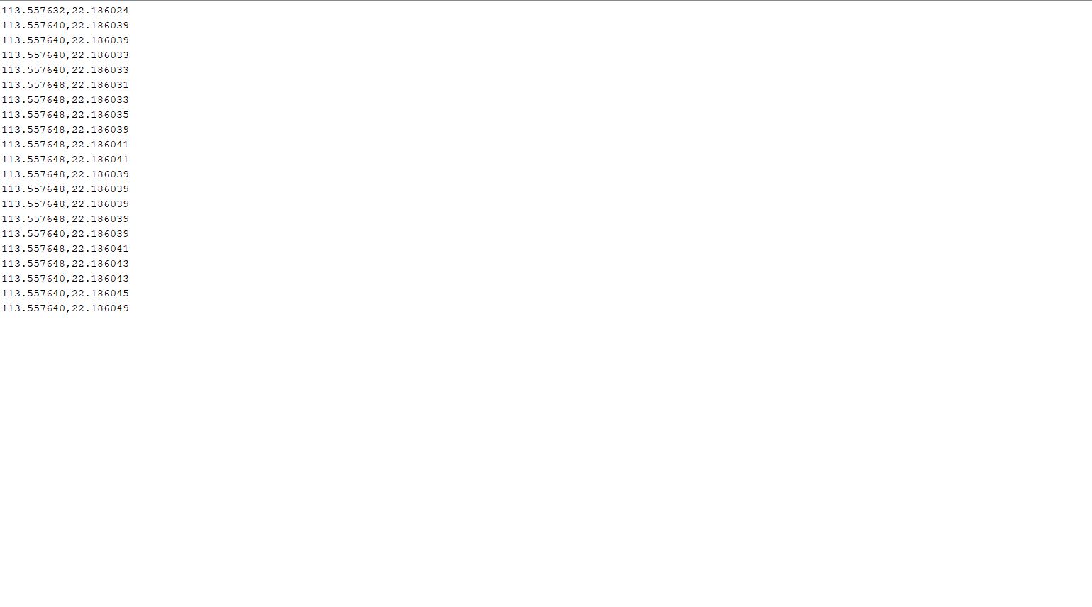
These information can be post-processed by Python for other application. Such as path record and show the path in the map.
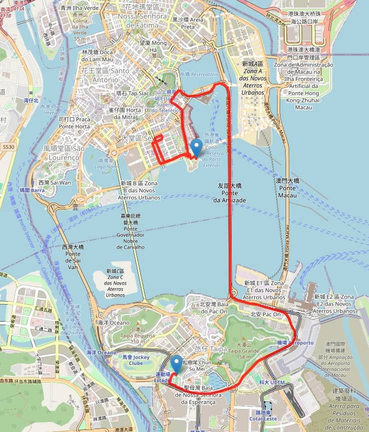
I connect the ESP32C3 to my laptop and connect the position data by Python. The information is collected to a txt file and draw the position data to a openstreet map. Here's the map web page.