Group Assignment
The assignment task: probe an input device's analog levels and digital signals
Input device
Joystick
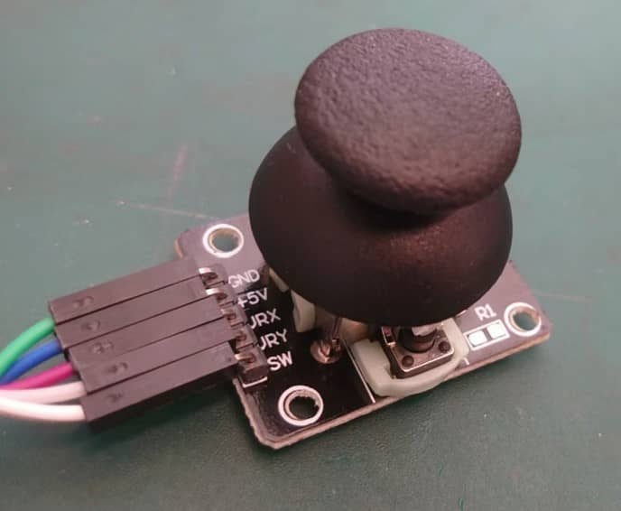
Why using joystick component?
These joysticks are typically small and lightweight, making them easy to integrate into various projects without taking up much space.
Also the joystick can be used as:
-
Analog Input: The joystick allows for multidirectional movement, enabling control along both the horizontal (X) and vertical (Y) axes. The X and Y axes generate analog outputs, which can be easily read by microcontrollers using analog-to-digital converters (ADCs). This allows for smooth and precise control in applications like robotics, gaming, or interactive interfaces.
-
Digital Input: The joystick modules also include a push-button feature, allowing the user to press down on the knob. The push-button functionality provides a simple digital output, which can be used for triggering events or actions in the microcontroller.
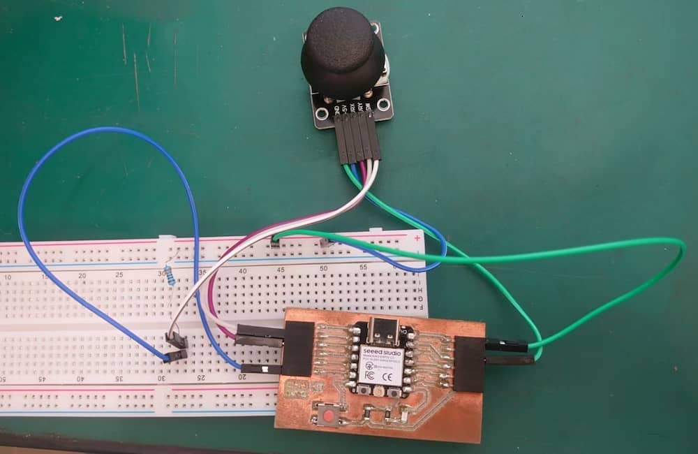
The circuit connection:
Programming
We program the MCU to read the analog reading of X and Y axes through D1 and D2 pin, and use D5 pin to read the digital signal of the push button.
Program
int Xpin = D1;   // select the input pin for X axis
int Ypin = D2;   // select the input pin for Y axis
int Knobpin = D5;  // select the input pin for push button

void setup() {
  Serial.begin(9600);
  pinMode(Knobpin,INPUT_PULLUP)
}

void loop() {
  Serial.print(analogRead(Xpin));
  Serial.print(" ");
  Serial.print(analogRead(Ypin));
  Serial.print(" ");
  Serial.println(digitalRead(Knobpin));
  delay(100);
}
Measure method
Serial Plotter
There is built-in data read function in the Arduino IDE, serial monitor(text form) and serial plotter(graph form). The analog reading result:
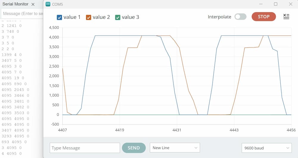
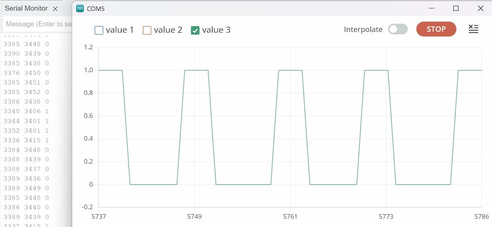
As the digital reading is 1 and 0, compare to the max analog reading(4095), it's too small to see the change compare to the analog reading, so we need to close the analog reading signal to see the digitial reading signal.
The digital reading result:
In order to become more intuitive, we hope to read the voltage value instead of analog reading.
The code is modified as below.
Program
Then, the y-axis of serial plotter will show the voltage value.
void setup() {
  // put your setup code here, to run once:
  Serial.begin(115200);
  pinMode(A2, INPUT);
  pinMode(A1, INPUT);
  pinMode(D5, INPUT);
}

void loop() {
  // put your main code here, to run repeatedly:
  float VX = analogRead(A2);
  float VY = analogRead(A1);
  VX = VX/4095.0*5.0;
  VY = VY/4095.0*5.0;
  int button_state = digitalRead(D5);
  Serial.print(VX);
  Serial.print(" ");
  Serial.print(VY);
  Serial.print(" ");
  Serial.println(!button_state);
  delay(50);
}
The digital reading result will become:
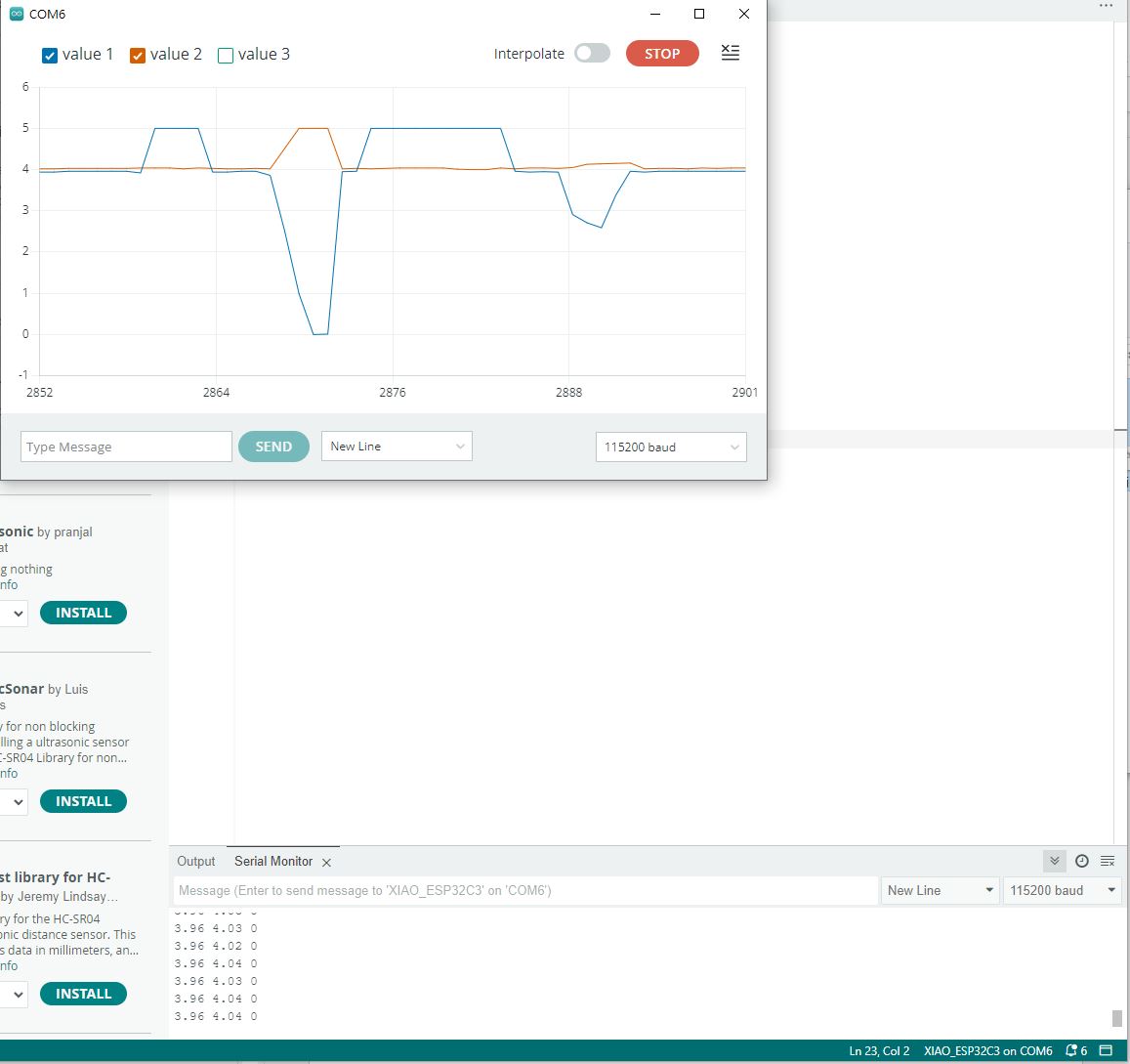
The y-axis of the serial ploter shows voltage value.