Week8 - Electronics Production
File Sharing
The task of the assignment
- Make and test a microcontroller development board that you designed
- Extra credit: make it with another process
Make the designed development board
I just designed a development board in week6, the designing process can be referred to week6 assignment.
Understanding the knowledge about the CNC machine.
Last week, we studied about the knowledge and how to use a CNC machine. The same knowledge can be used for a smaller CNC machine for electronic production.
Machine for electronic production
In this assignment, I will do the electronic production by a machine MODELA MDX-50 Benchtop CNC Mill.
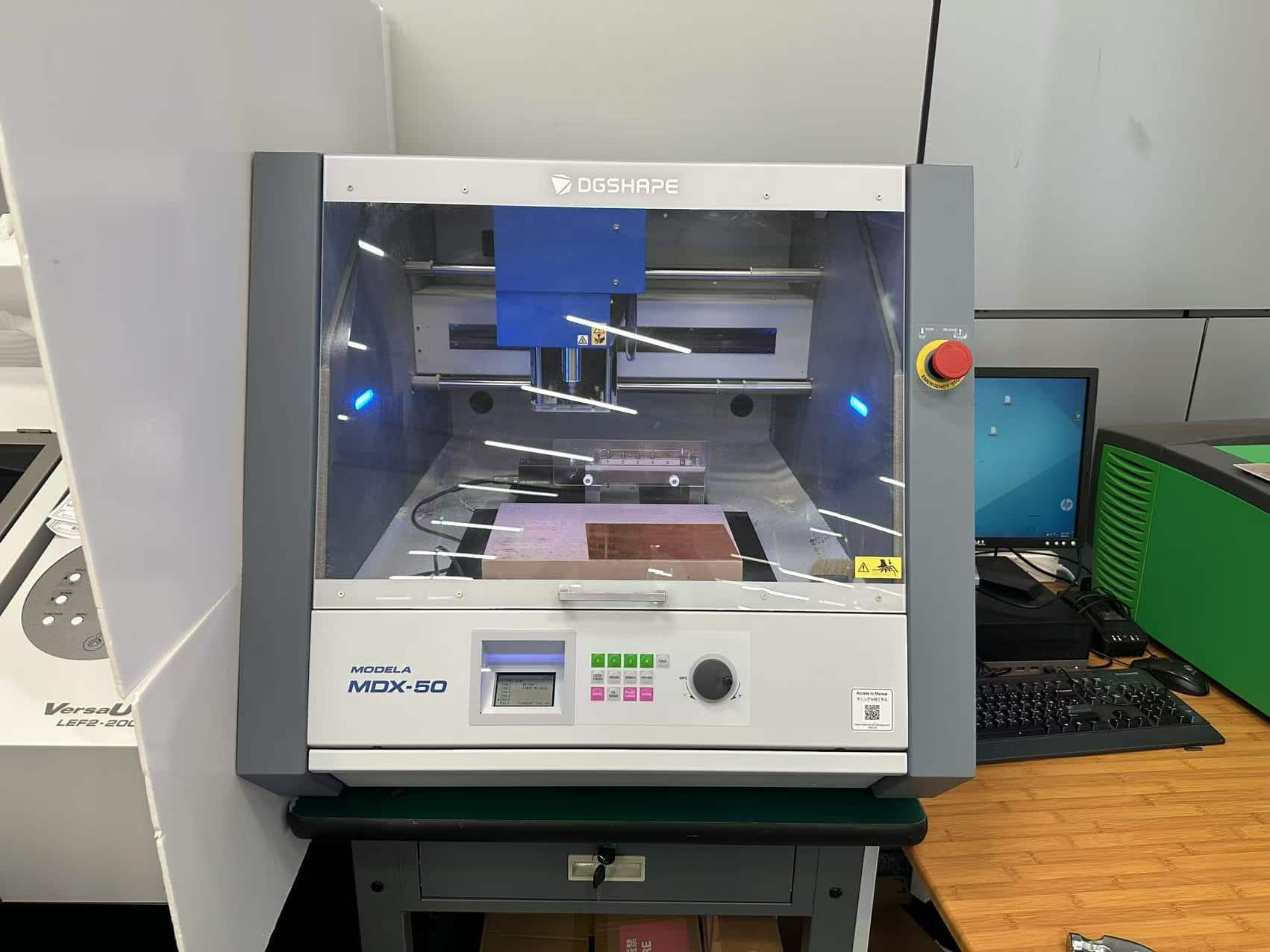
This machine is used for making accurate protoypes. For example, milling a mold(which is week 13 assignment).
Here's the specification of MDX-50 machine.
| Max Working Area(X,Y,Z) | Table Size | Tool Shaft Diameter | Number of tools in toolchanger | Max Feed Rate | Mechanical Resolution | Cutter Rotation Speed | Control Software |
|---|---|---|---|---|---|---|---|
| 400 x 305 x 135 mm | 400 x 305 mm | 3 mm, 4 mm, 6 mm, 1/8", 1/4" | 6 (one of the tools is the detection pin) | 60 mm /sec | 0.01 mm | 4500 - 15000 rpm | Roland V-Panel, SRP Player |
According the document of FABLAB Brighton in 2018, the MDX-50 machine can used for milling a circuit board. We will make a development board by this machine.
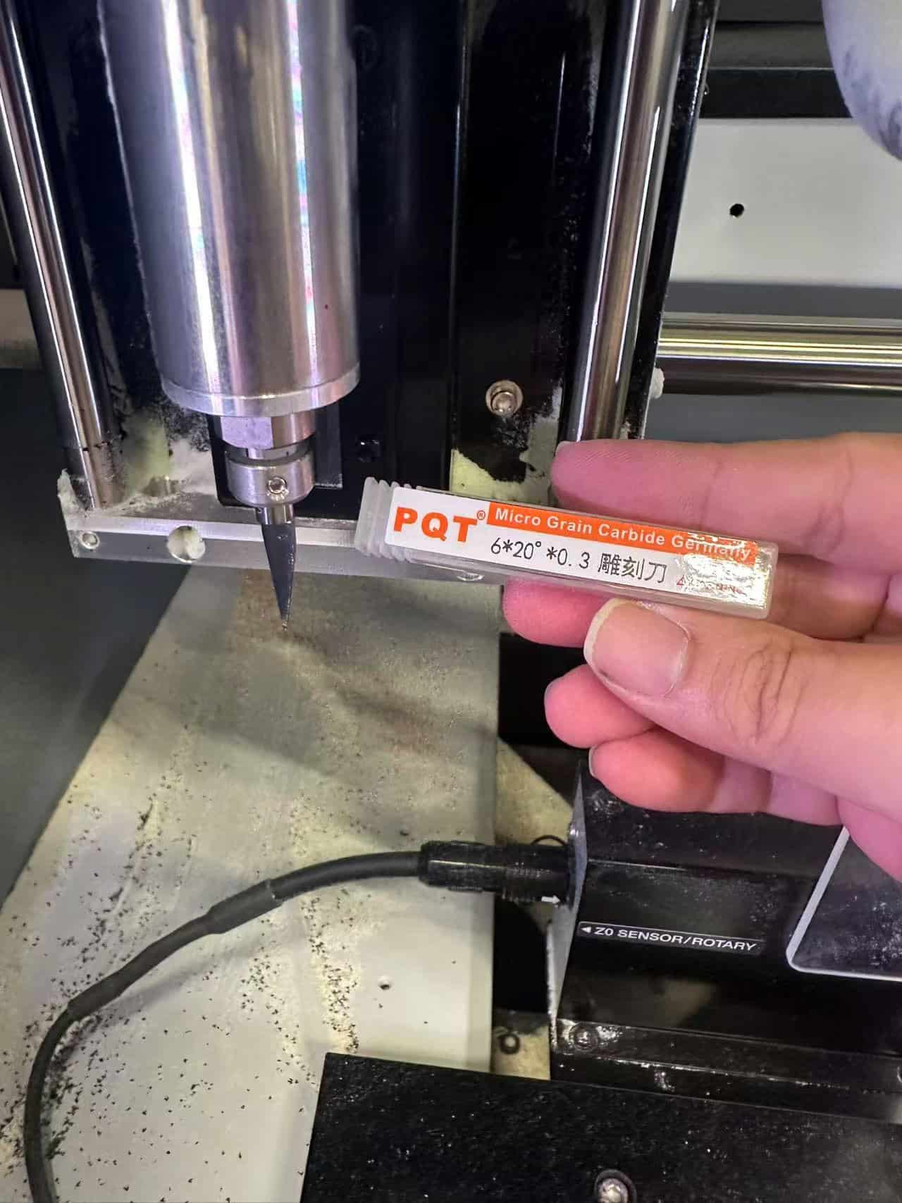
There's only V-bits can be used for milling the circuit board in our inventory of lab.
Here's my parameters of milling tools.
- V-bits. 6 * 20 * 0.3 V-bit for tracing
- Ball end tool. 1.5 * 0.3 for outline cutting
How does whole thing work
It requires "G-code" to make the CNC machine work. And there are multiple ways to generate G-code.
- Option 1 : Directly using "Mods CE" tool to generate the G-code, it requires PNG or SVG images since they are lossless resolution.
- Option 2: Uploading the Gerber files to the related software of the CNC machine and let it generate the code.
For both options, they all require the configuration of the parameters, which mean I need to know and need to:
- How thick is the board so that I can set the depth of the cut
- Set different parameters for different tools(1/64 end mill, 1/32 end mill, V-bit, etc)
- Set a reasonable width to keep the connection simple without cutting it
- Set the original point(zeroing)
For the safety and the lifetime of the machine and the tools, there are something that need to be awared:
- There should be a backing plate under the cutting board, which is generally wood
- The base and the board to be cut should be secured
- Determine the position at the beginning, ensure the origin, do not click "return to the origin" until you have a clear orientation
- These are the preparations for cutting.
Preparation
Components
Here's a sample project for XIAO RP2020.
Refer to this project, I have designed another development board in week6 assignment. The following electronic components will be prepared
| Component | Quantity |
|---|---|
| SEEED STUDIO XIAO ESP32C3 | 1 |
| CONN HEADER SMD 10POS 1.27MM | 1 |
| CONN HEADER SMD R/A 6POS 2.54MM | 1 |
| Tactile Switch SPST-NO Top Actuated Surface Mount | 1 |
| LED BLUE CLEAR 1206 SMD | 3 |
| RES 1K OHM 1% 1/4W 1206 | 4 |
| RES 499 OHM 1% 1/4W 1206 | 1 |
| CONN HDR 7POS 0.1 TIN SMD | 2 |
Circuit
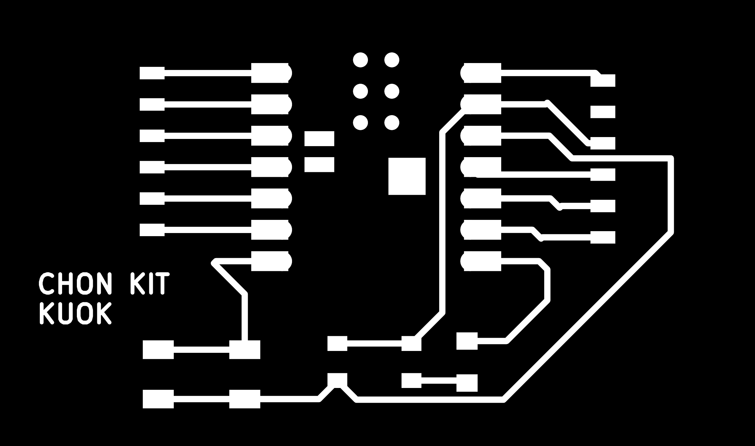
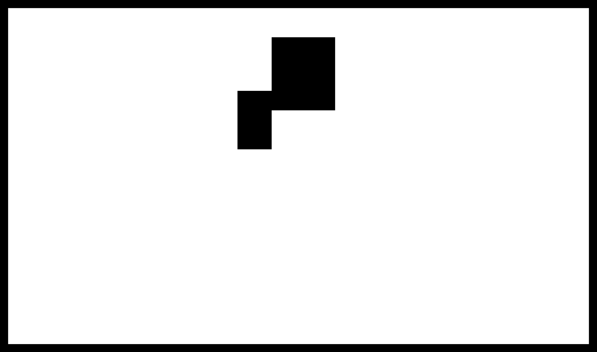
We have finished designing the develop board in week6 assignment. We will use the following circuit image for tracing and outline cutting, respectively.
G Gode Generate
In my case, MODELA MDX-50 Benchtop CNC Mill will be used. Mod CE can used for generating the G Gode for milling circuit board with MDX-50 machine.
After getting into the website, click mouse right button and choose "program".
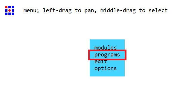
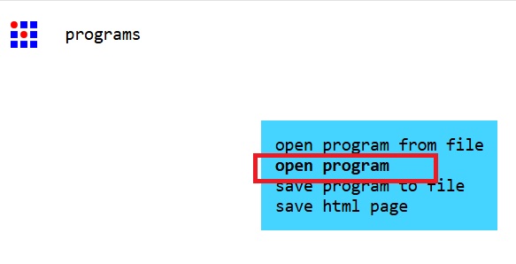
Choose "Open Program"
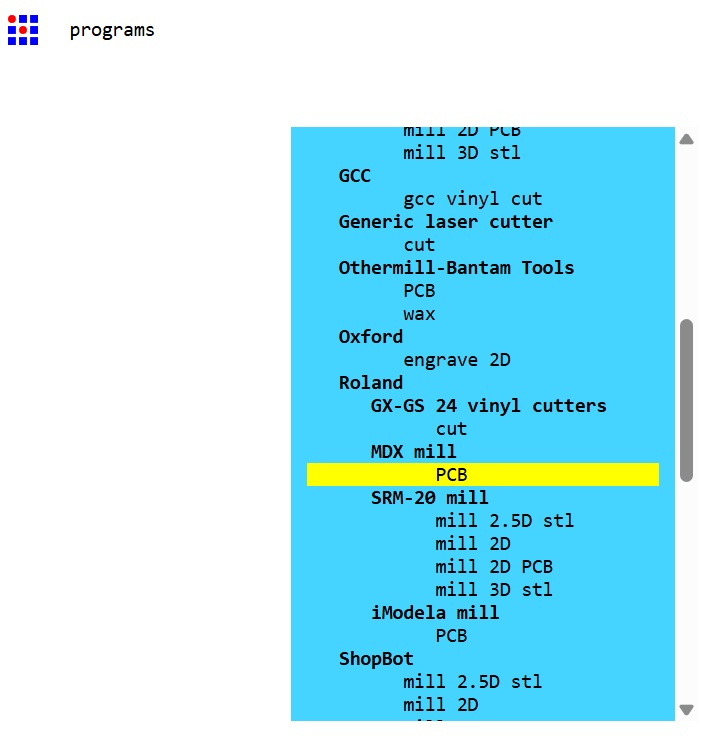
Choose Roland->MDX mill->PCB
Then, there's a large interface appeared.
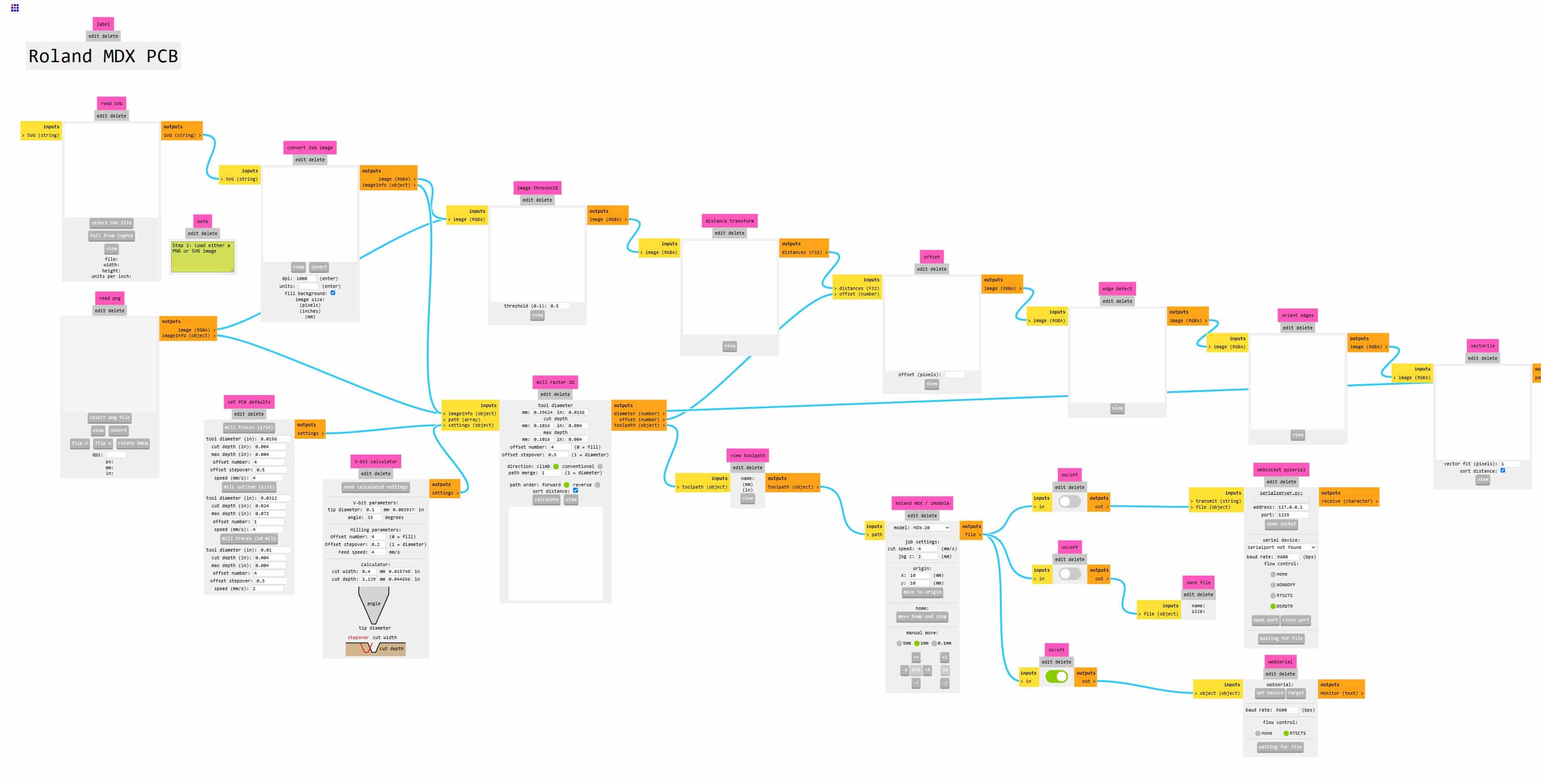
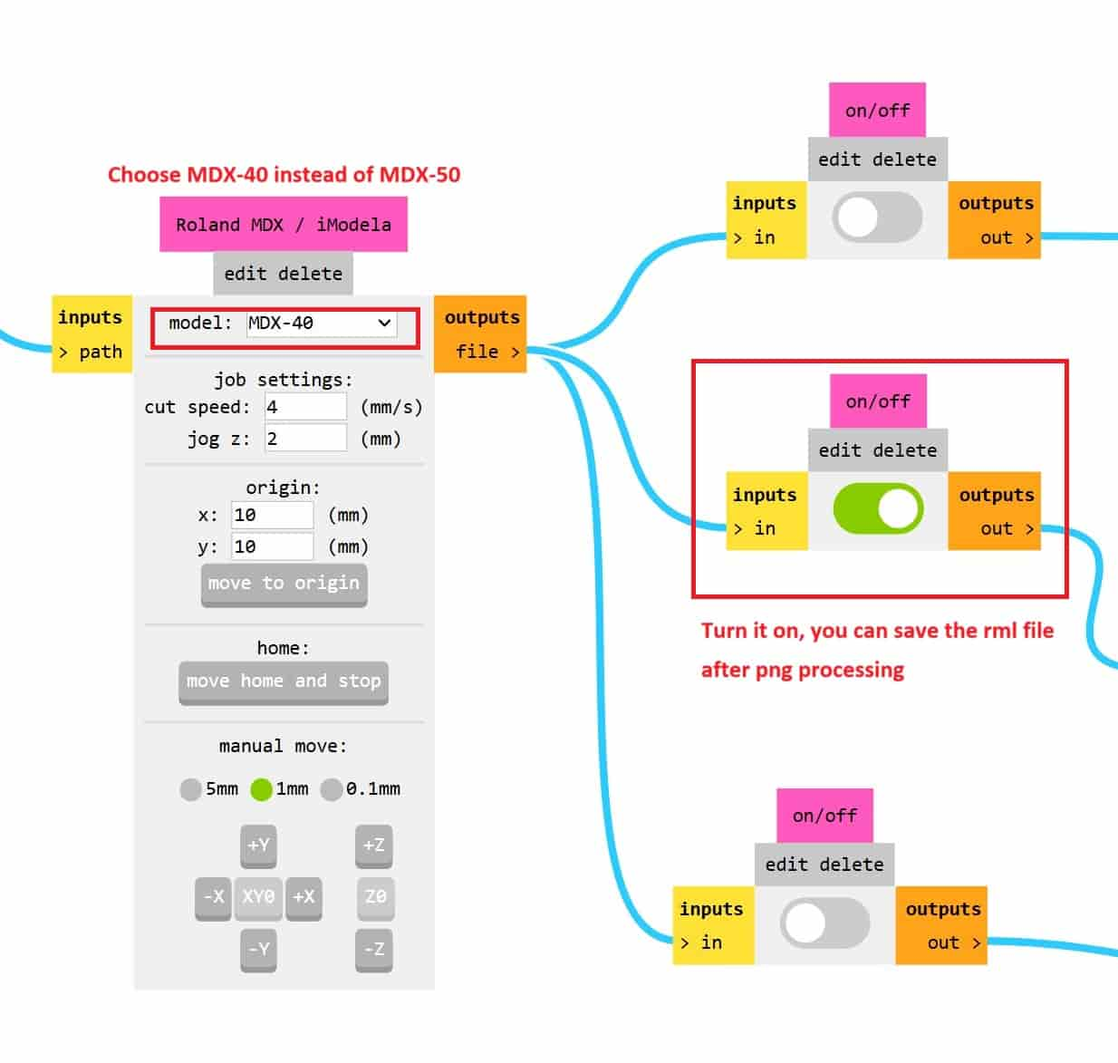
First, change the machine model to MDX-40(No MDX-50 can be choosed but it works!!) and turn on the middle button which allows saving the rml files after the png processing.
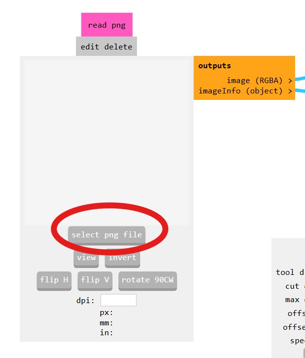
Then, read the png image.
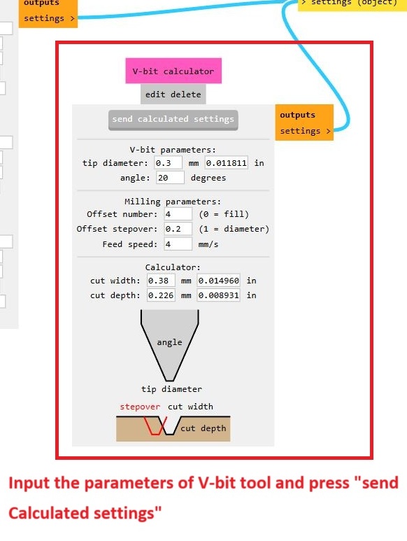
Setup the tool paramters in "V-bit calculator"(in this case we choose using V-bits as milling tool) and press "send calculated settings".
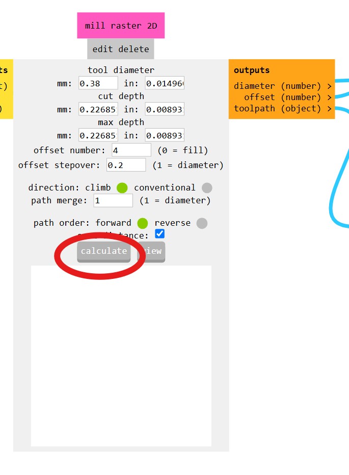
Then, press "Calculate" to generate the rml file.
You can also see the tracing simulations.
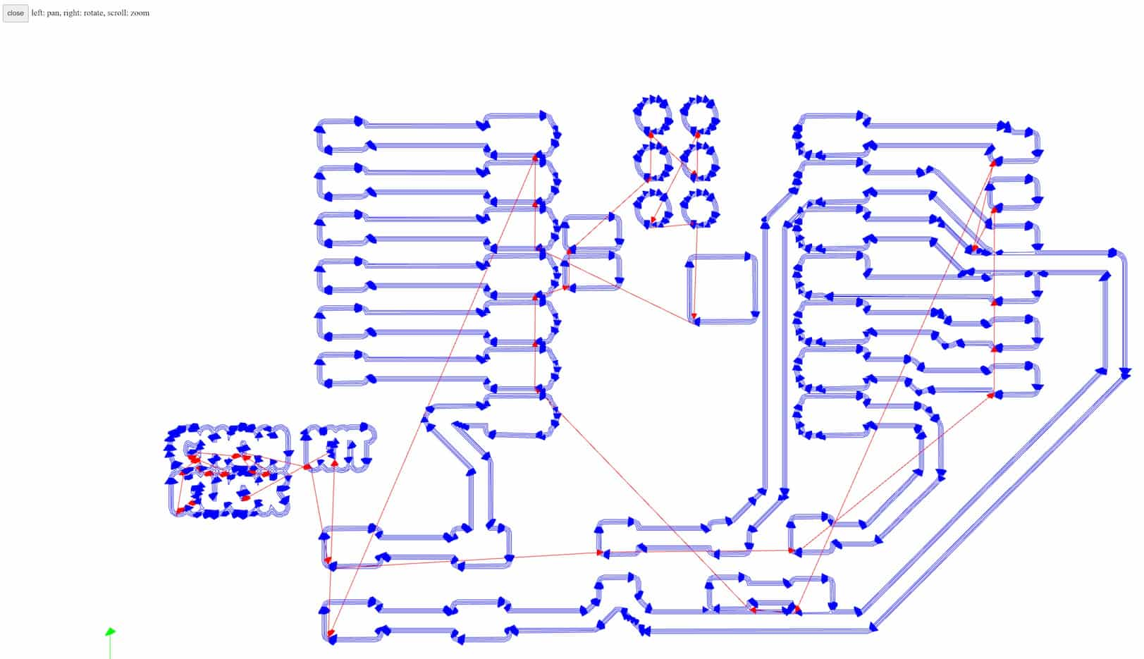
After generating the tracing G code file, reload the webpage and repeat the steps above. This time we read the outline file and input the tool parameters as following for outline cutting.
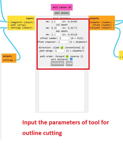
Press "Calculate" and generate the outline cutting rml file. The simulation of milling just like below.
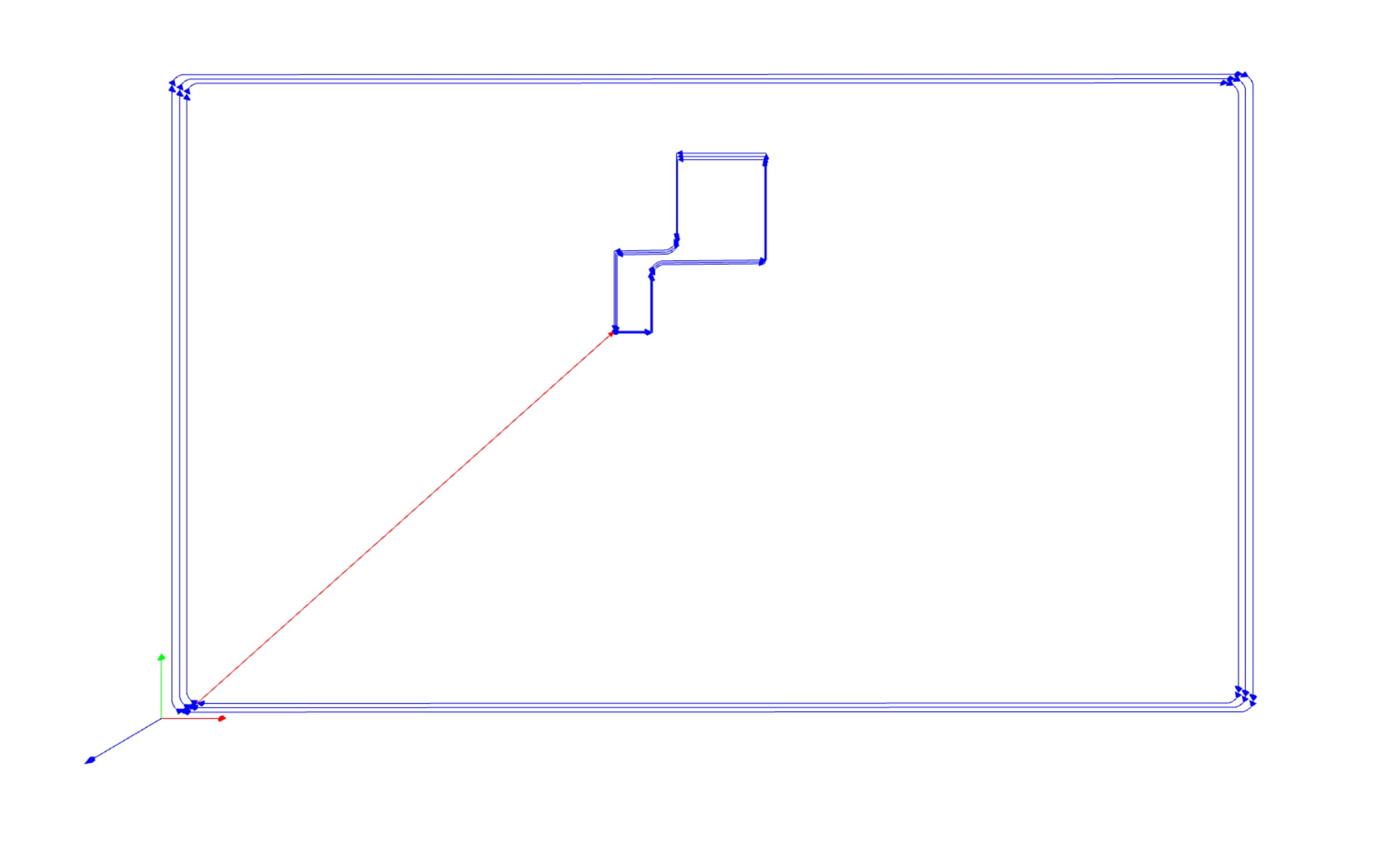
After generating the tracing and cutting G-code, let us begin milling the PCB board!!
MDX-50 setup
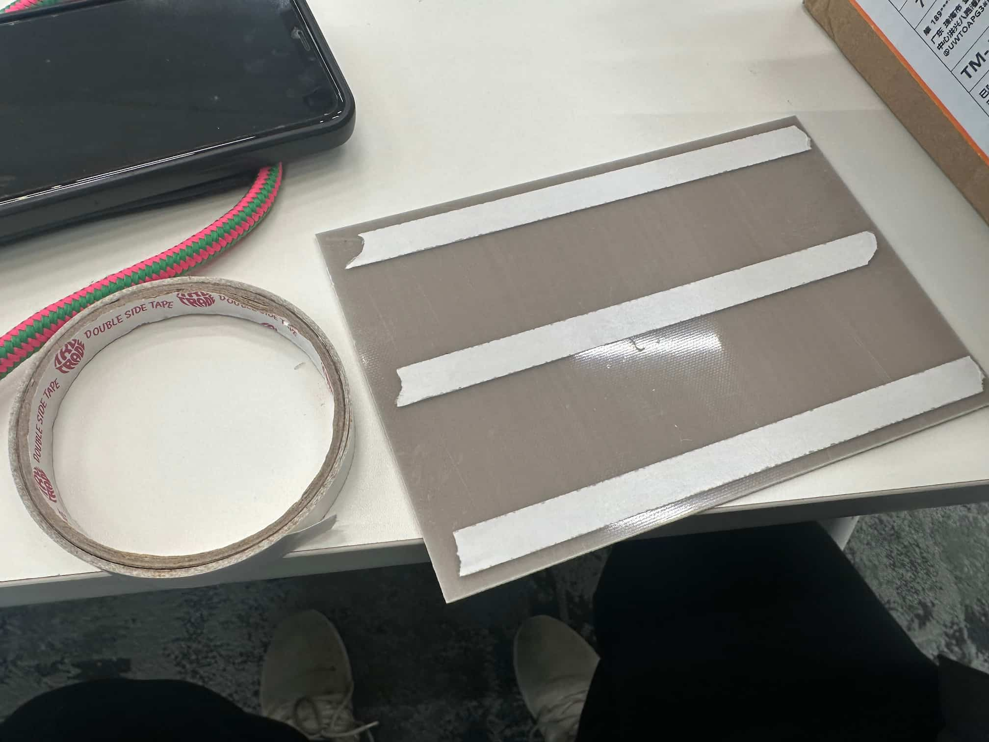
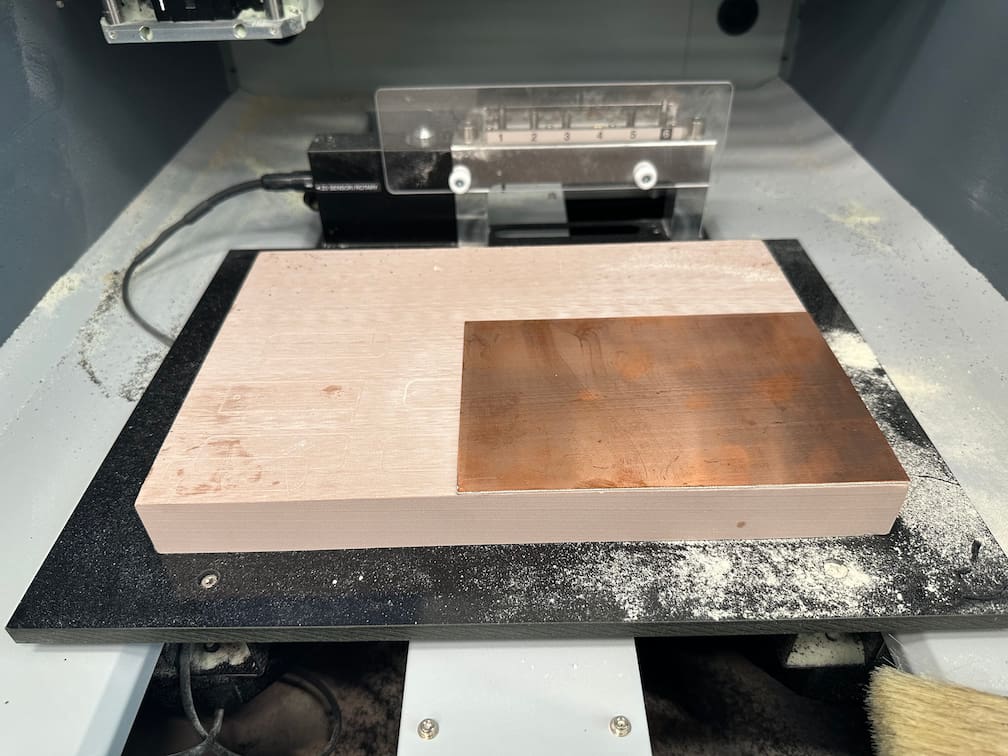
Place the copper fiber board
First, we have to place the copper fiber board to the CNC machine by double-side tape to fix the board.
Setup X, Y, Z origin points
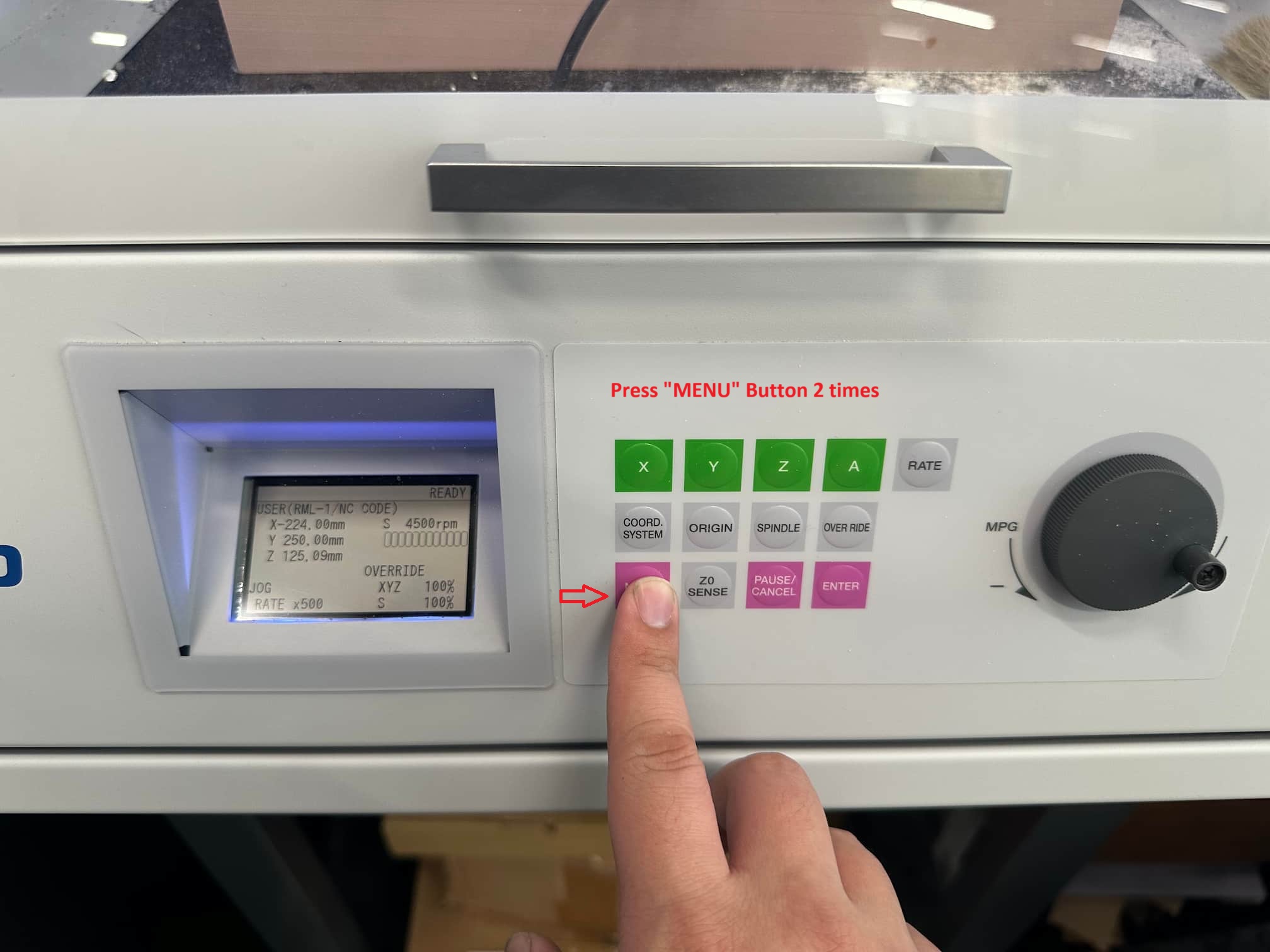
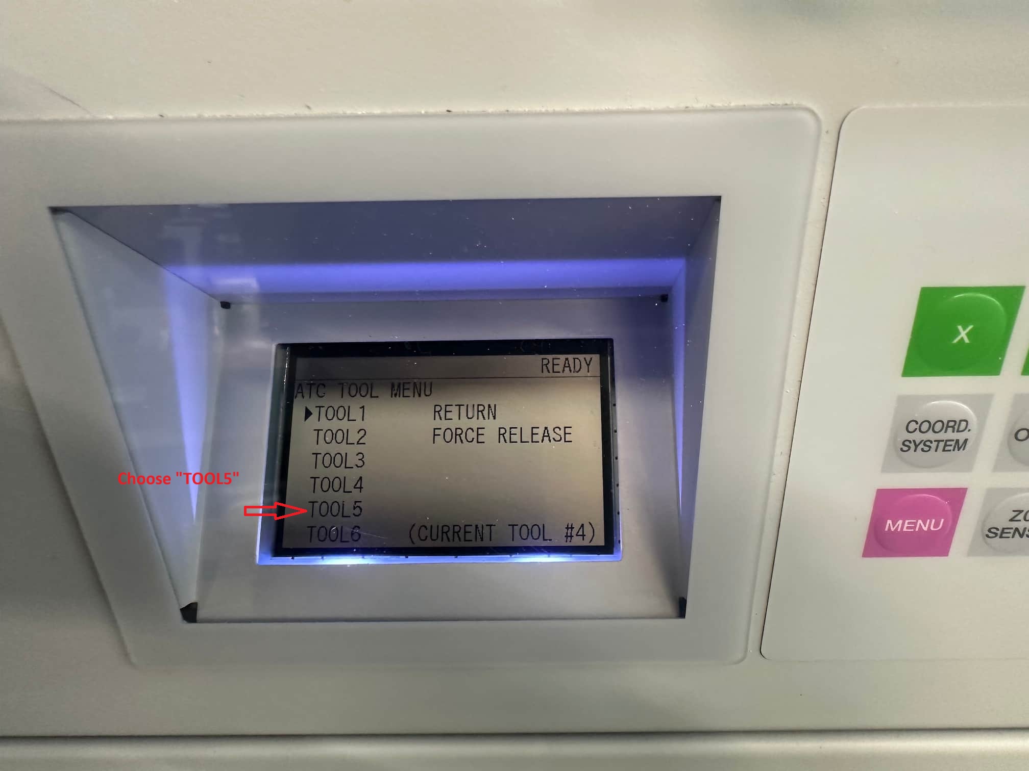
Before calibrate the XYZ coordinate, the tool will be set up first. In this assignment, V-bits tool will be used. V-bits tool is set as tool 5 in our machine. Press "MENU" button 2 times and go choose "TOOL5" to change the milling tool.
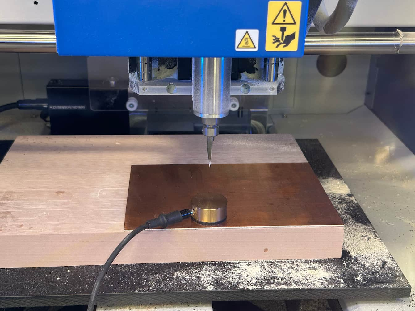
Then, put the Z0 sensor to a position where you want to setup the origin point(X0, Y0). And move the tool above the Z0 sensor. Just like the following photo.
Then, setup the X0, Y0 point, just like the following photo.
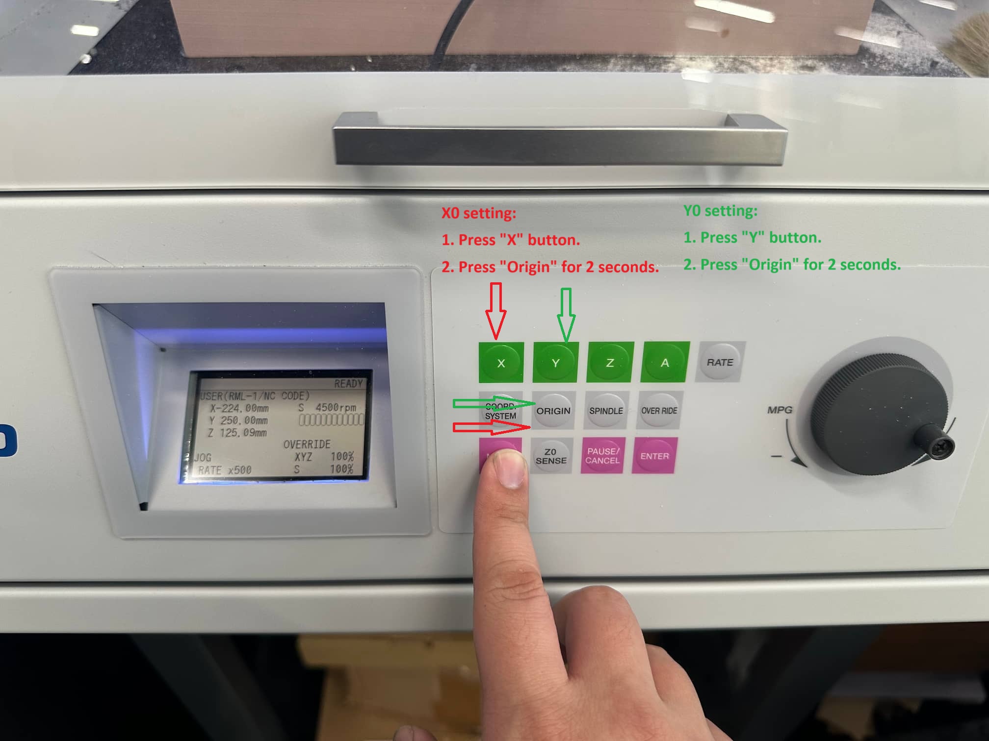
Remove the Z0 sensor, it's ready the operate the G code!
Start milling
Reading rml file
Roland VPanel is a software which is used for controlling MDX-50 milling machine.
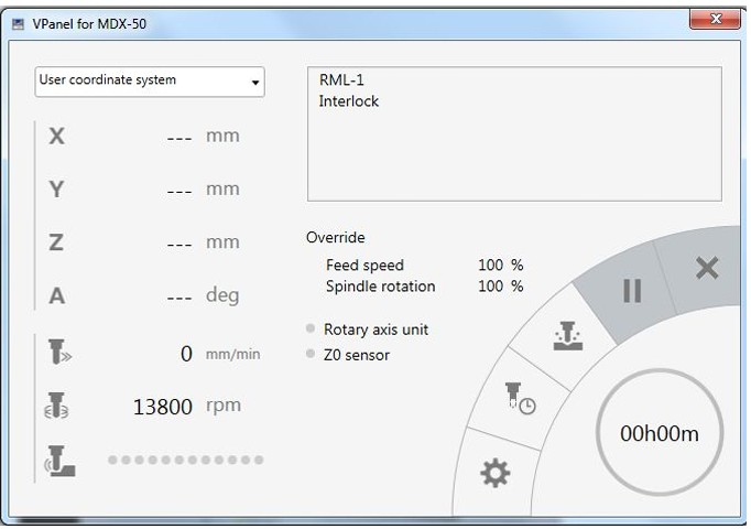
Click the button and read the .rml file which is generated from Mod CE.
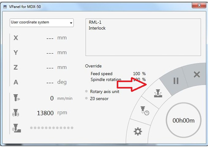
After reading the rml file and press the start button, the milling is started! Please move the tool above the origin point first before starting milling job!! Turn the spindle speed to 14000 rpm after starting the milling job.
Milling and post-processing
First, I test tracing the circuit in different area of the copper fiber board.
But I forget the reset the Z0, it case the milling depth is not enough. Just like the following photo.
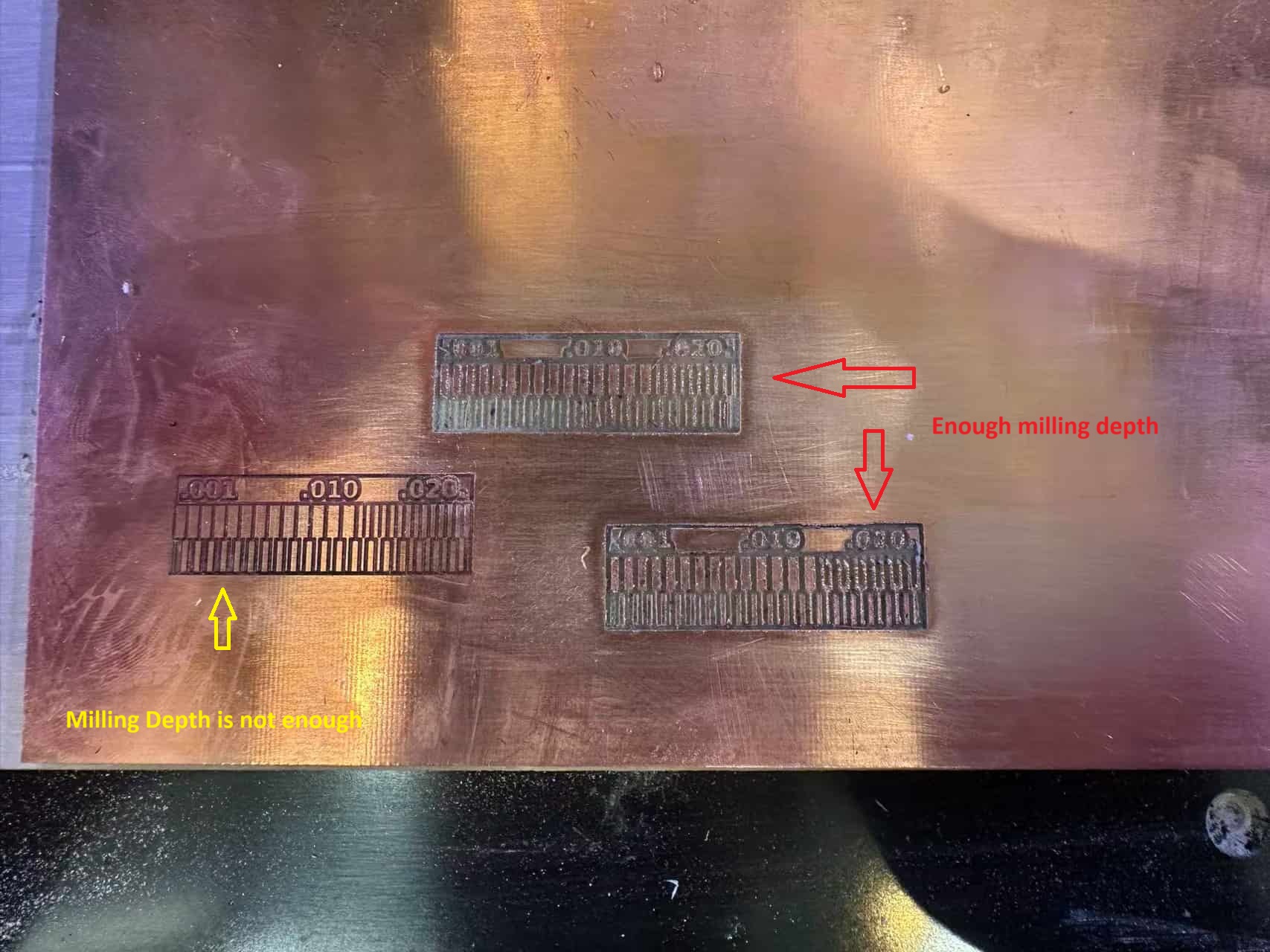
The cutting region which is marked as yello arrow show that the milling depth is not enough, it case the invaild circuit milling. The cutting region which is marked as red arrow show that the milling depth is enough, it can be used. There are lots of burrs in the surface of the development board, I will do the post-process after the milling job.
Finally, I found out an optimize cutting region.
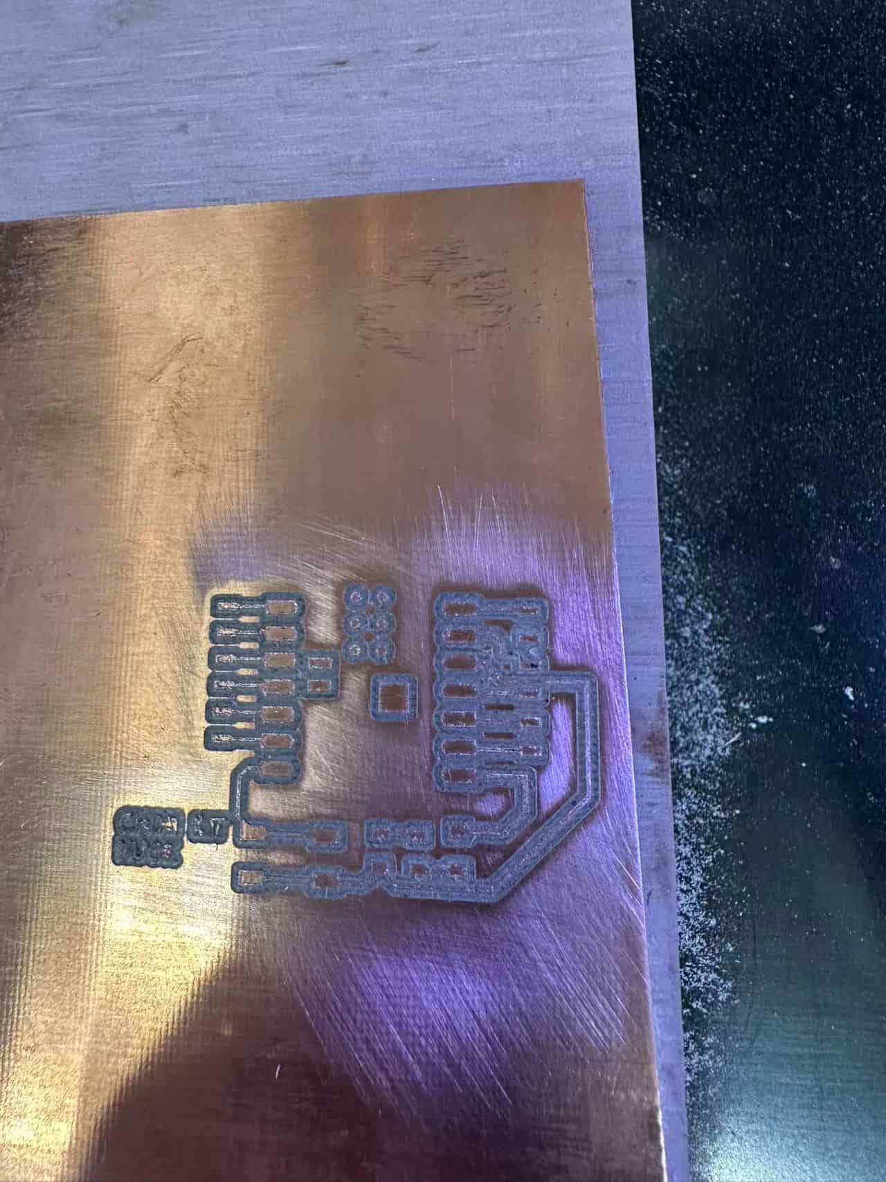
Then, change the Ball End Milling Tool(which is located at TOOL4). Repeat the step from reading rml files in VPanel Software and choose the outline cutting G-code file, to cut the outline of the development board.
Then, I remove the burrs of development board by using sand paper.
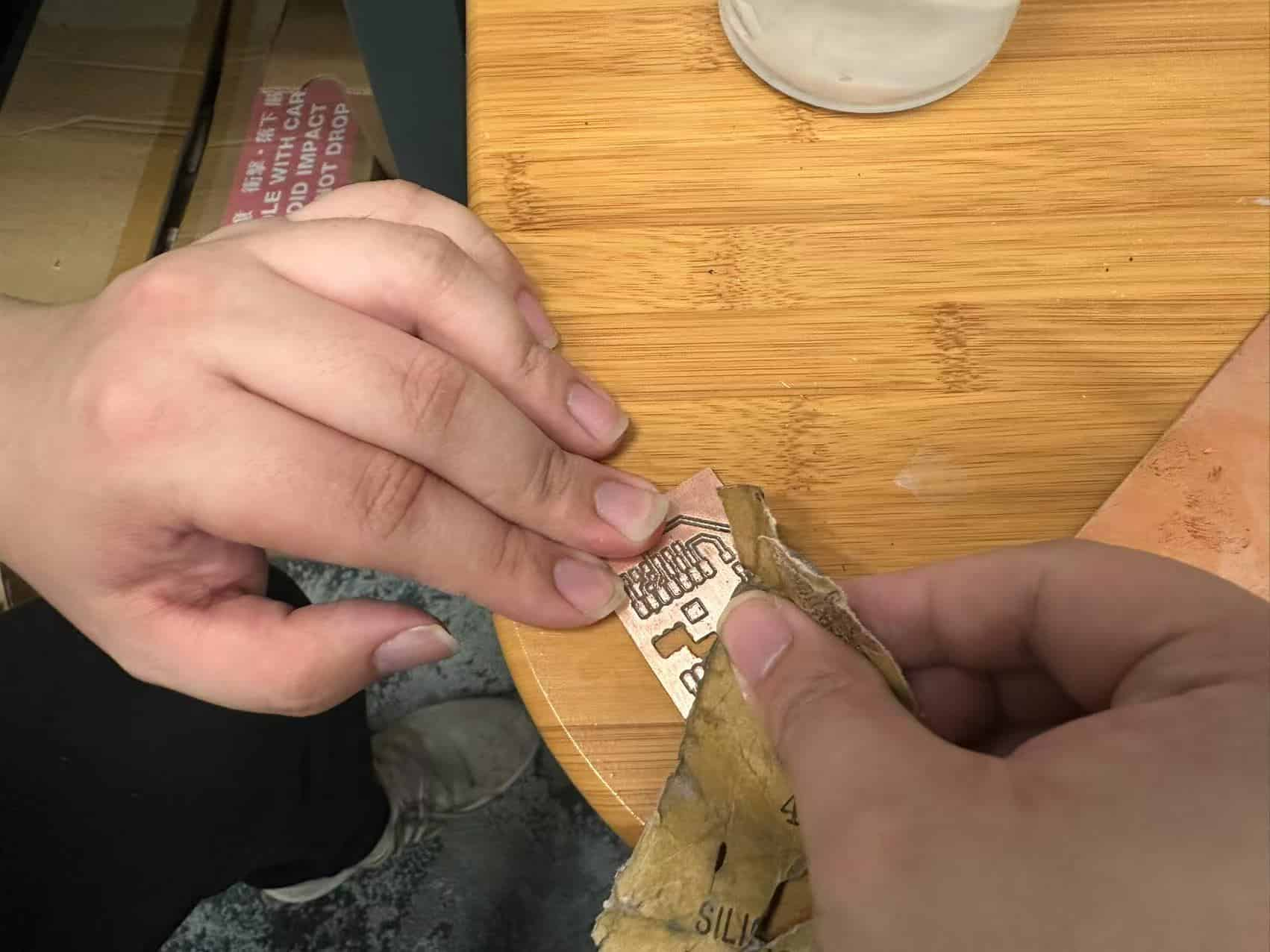
The layout job of the development board is finished!!
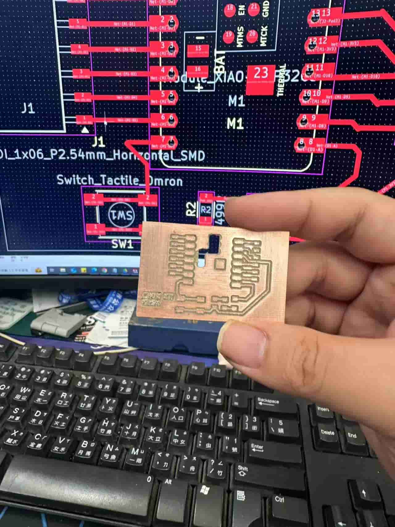
Soldering
Then, in order to finish making a development board, I will solder the electronic components to the development board.
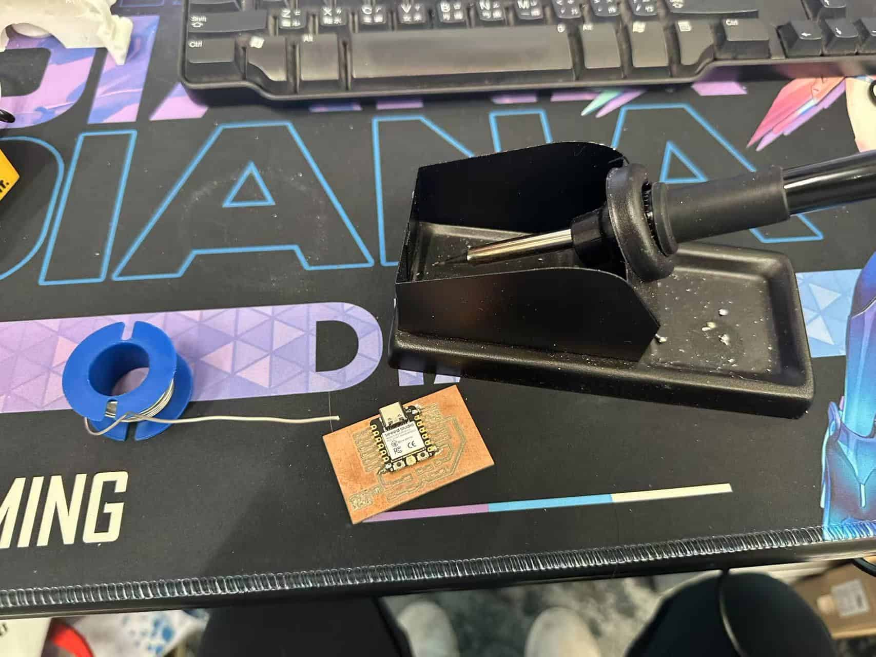
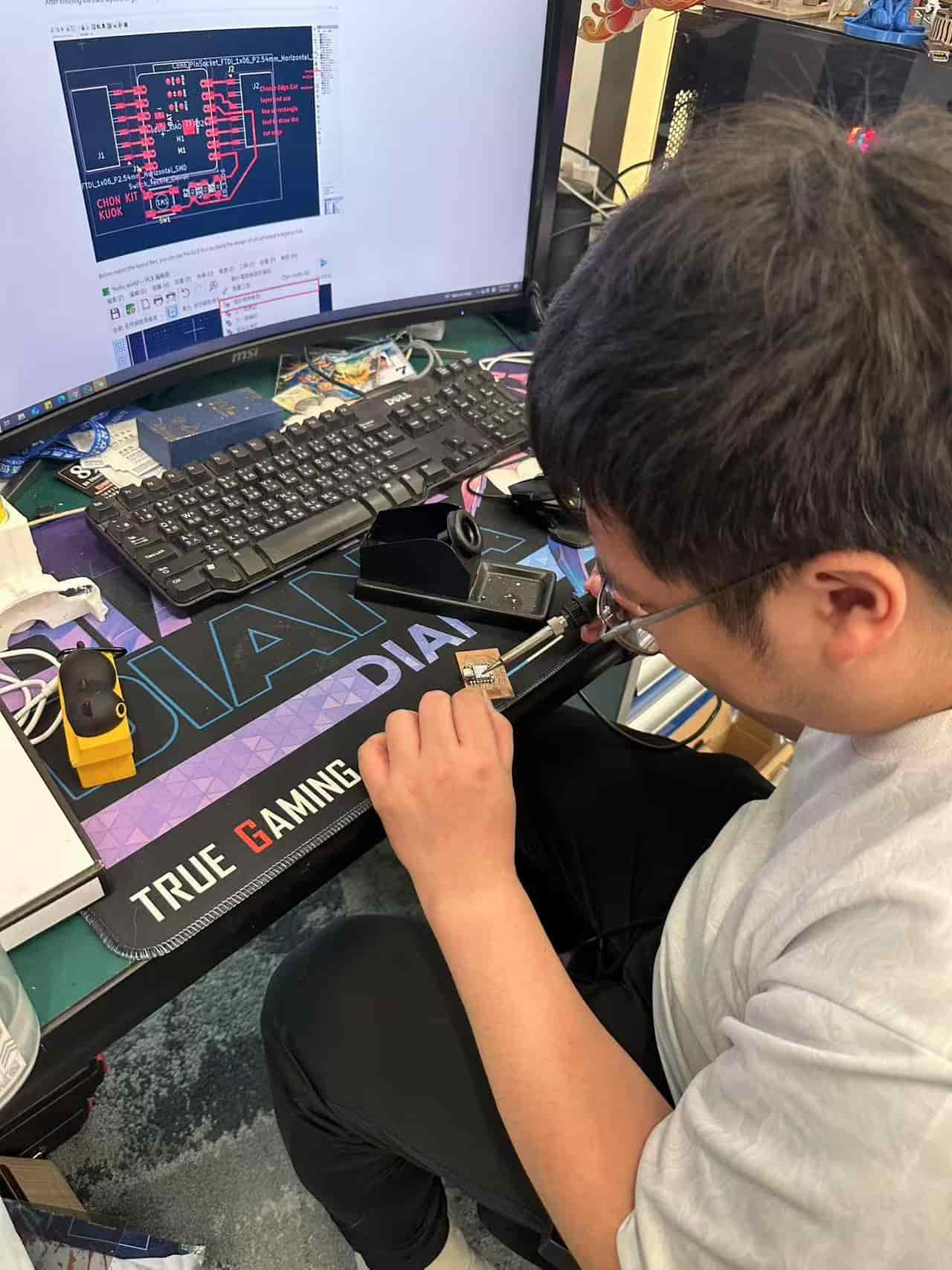
First, I solder the ESP32C2 onto the development board.
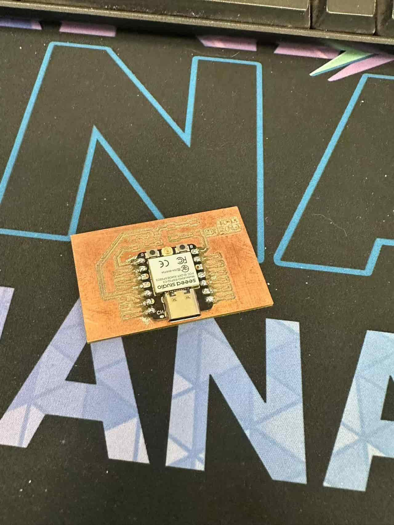
It's my first time to solder the SMD components. I feel it's diffcult to solder a tiny component (1206) onto the development board. A forceps is needed to fix or clip the components.
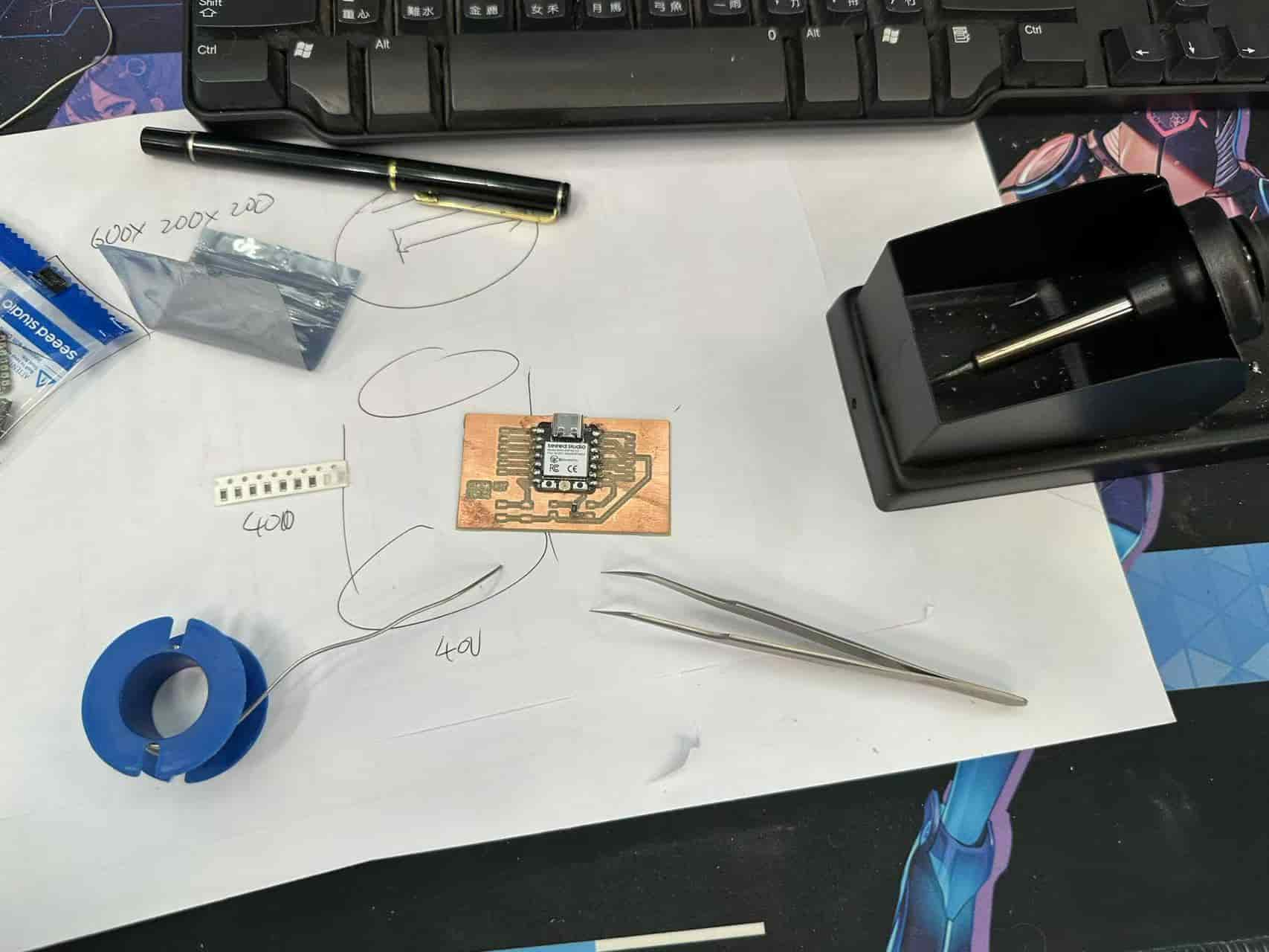
It's almost finish....
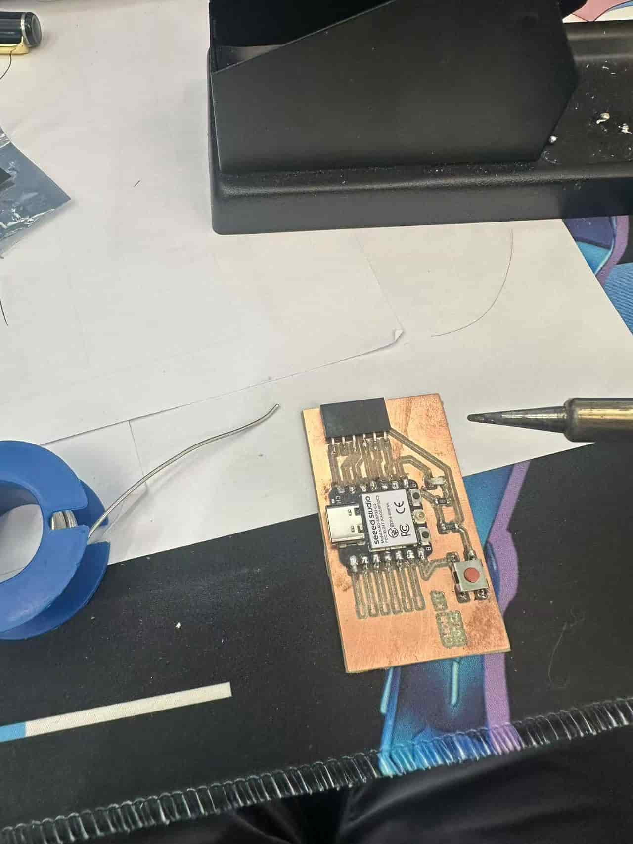
Finally, the development board is finished after soldering the components.
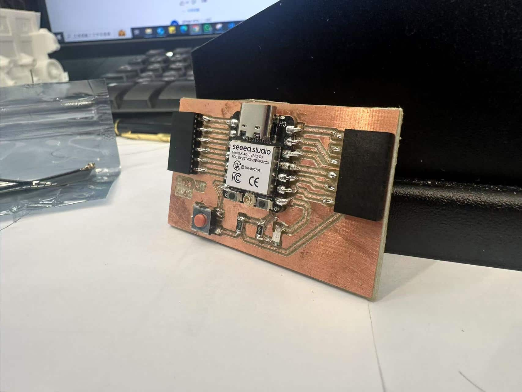
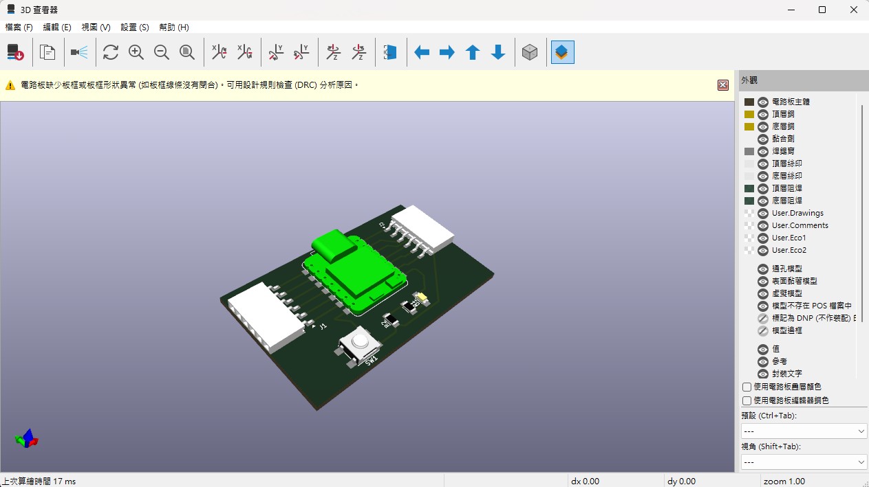
Let's comparing with the 3D simulation.
Board Testing
Simulation
Before testing the development board, I built a simulation in wokwi which's circuit is same as the development board in this assignment.
void setup() {
  Serial.begin(115200);
  pinMode(D6, INPUT);
  pinMode(D7, OUTPUT);
}

void loop() {
  digitalWrite(D7, LOW);
  Serial.println(digitalRead(D6));
  if(digitalRead(D6) == HIGH){
    digitalWrite(D7, HIGH);
  }else{
    digitalWrite(D7, LOW);
  }
}
A button with pull-down resistor is used for input, a LED is used for output. I set LED turn on when the button is pressed.
Test the development board
After finishing the simulation, I upload the simulation program to the development board.
Other application of the development board
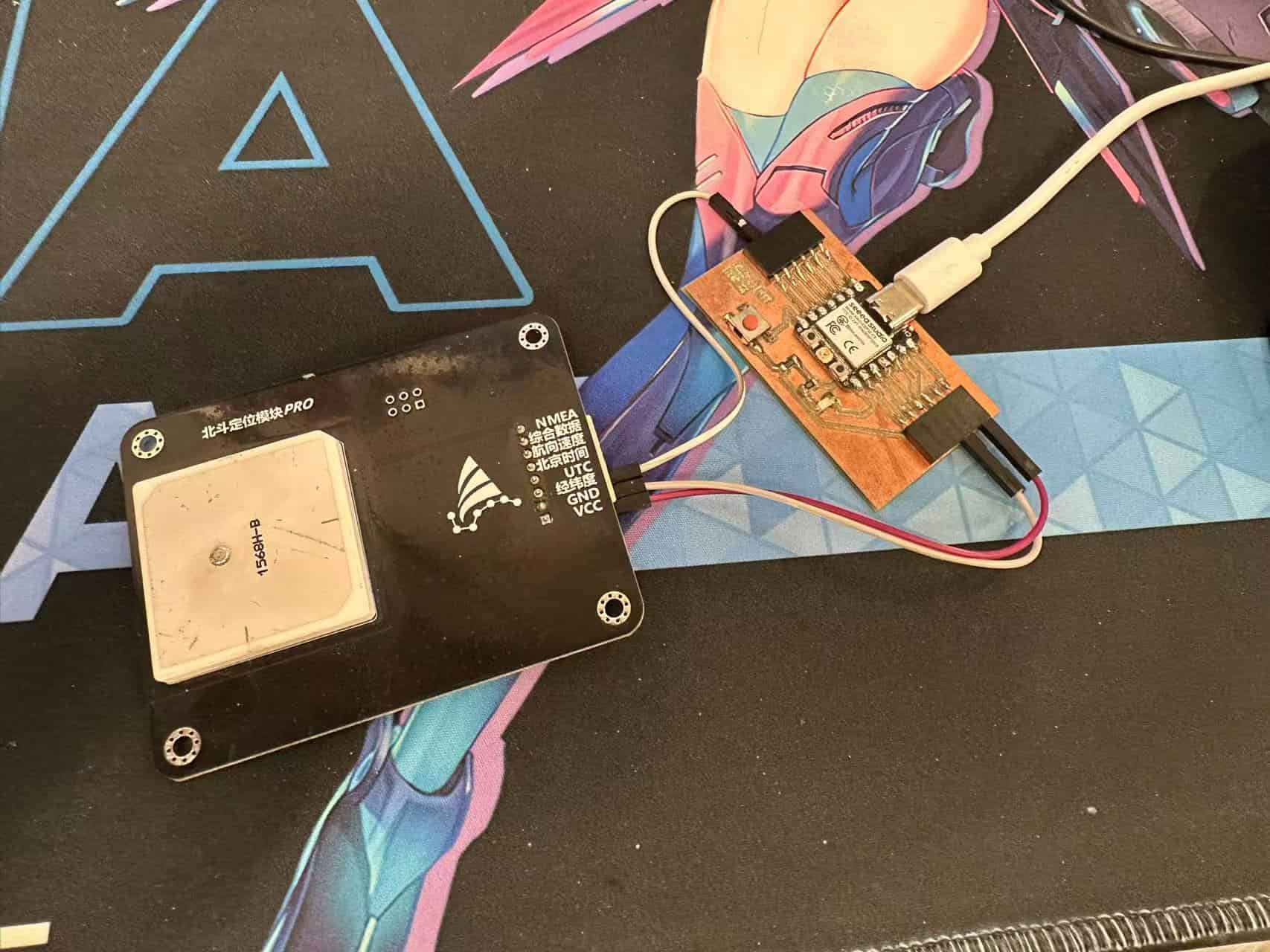
The designed development board can be used for other developments. For example, I connect a BeiDou Satellite (BDS) Antennia module to development board.
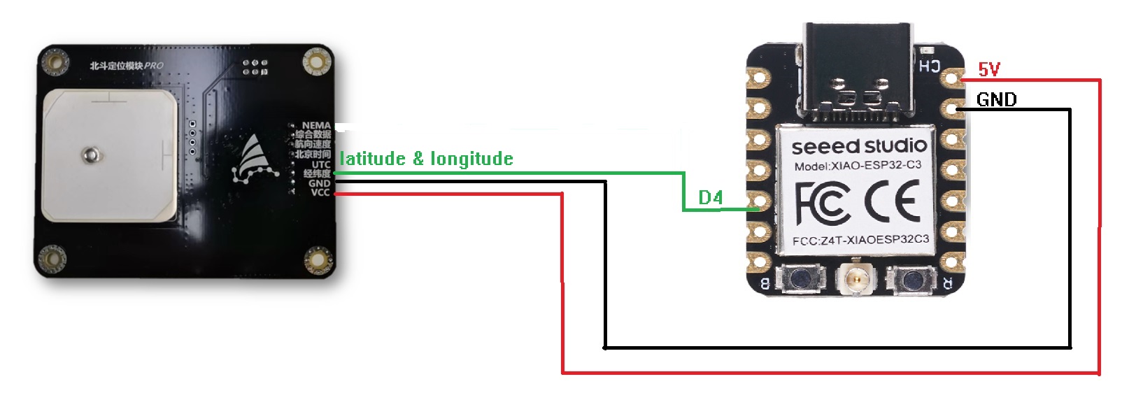
There are too many pins on the BDS Antennia module. In this assignment, I will just getting the information of positioning(latitude and longitude).
The communication protocol between the module and ESP32C2 is UART, and there's no other serial RX pin at the XIAO ESP32C2. I setup a software serial at D4 and D3 as RX2 and TX2, respectively.
#include <SoftwareSerial.h>
SoftwareSerial MySerial(D4, D3);

void setup() {
  // put your setup code here, to run once:
  Serial.begin(115200);
  MySerial.begin(9600); // at CPU Freq is 40MHz, work half speed of defined.

}

void loop() {
  // put your main code here, to run repeatedly:
  if(MySerial.available()!=0){
      String NMEA_BD = String(MySerial.readStringUntil('\n'));
      Serial.println(NMEA_BD);
  }
}
Finally, I can receive the position information from the Antennia module.
