3. Computer Controlled Cutting
Assignment for the week 3
-
Group assignment: characterize your laser cutter’s focus, power, speed, rate, kerf, joint clearance and types
-
Design, laser cut, and document a parametric construction kit, accounting for the laser cutter kerf, which can be assembled in multiple ways and try not to waste card board.
-
Cut something on the vinyl cutter
The link to the group assignment is here
Laser cutting
Our Lab has three different laser machine:
- Trotec speedy 400 flex
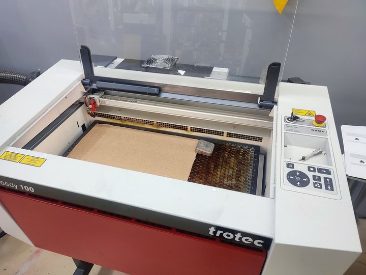
- Trotec Speedy 100
- Mr.Curve
I will be using Trotec Speedy 100
Designing Parametric construction kit on Fusion360
-
Start Fusion360.
-
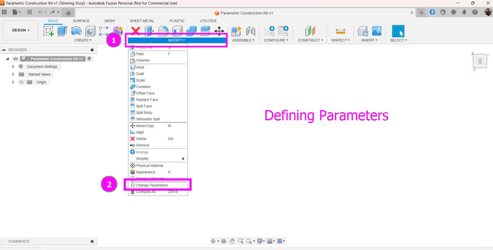
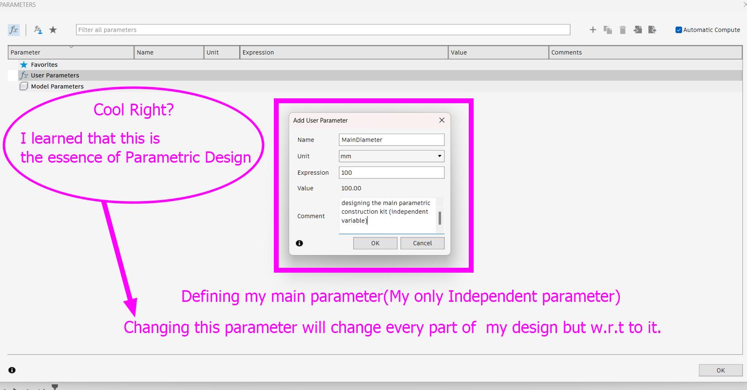
Go to Modify>>Parameters and give all the parameter required for your design
-
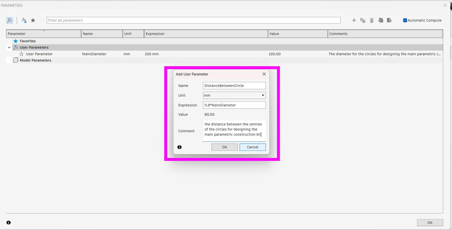
Defining a main independent variable for my parametric construction kits.
-
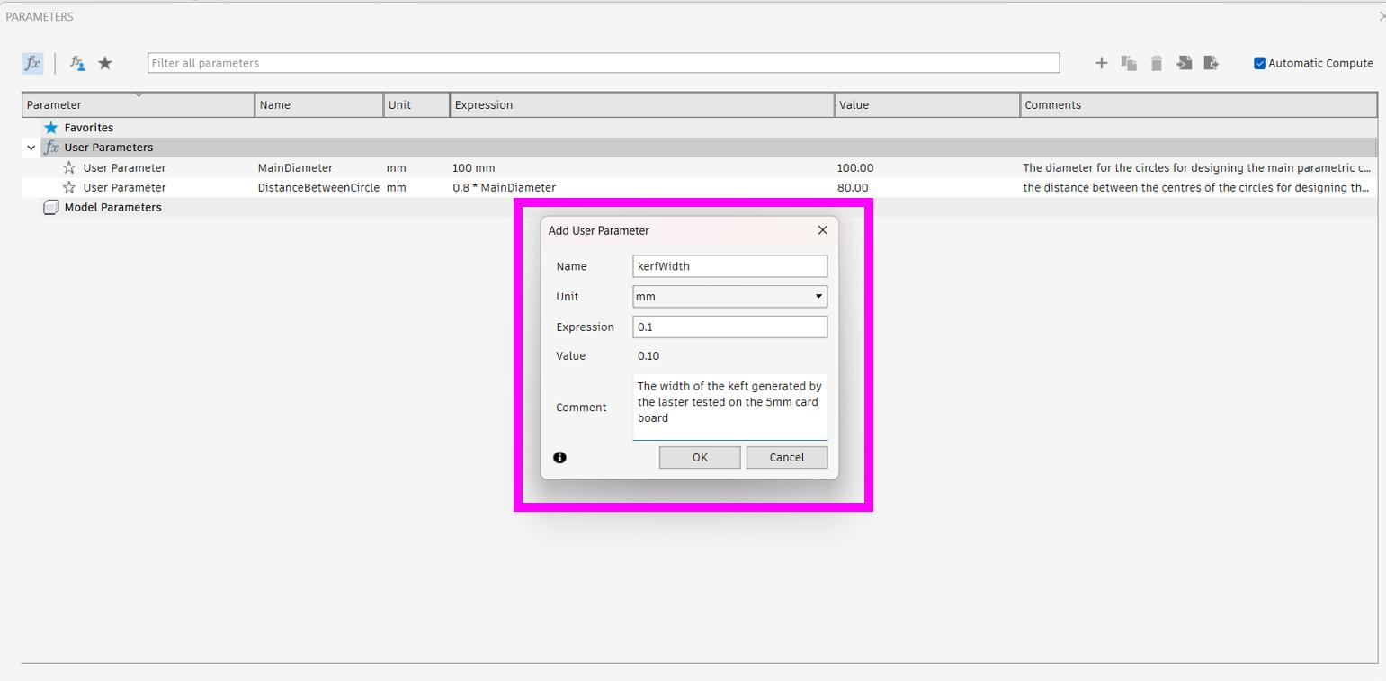
Defining kerf Width.
-
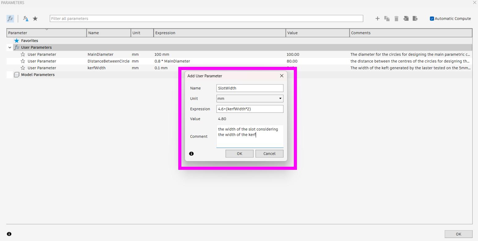
Defining Slot Width.
-
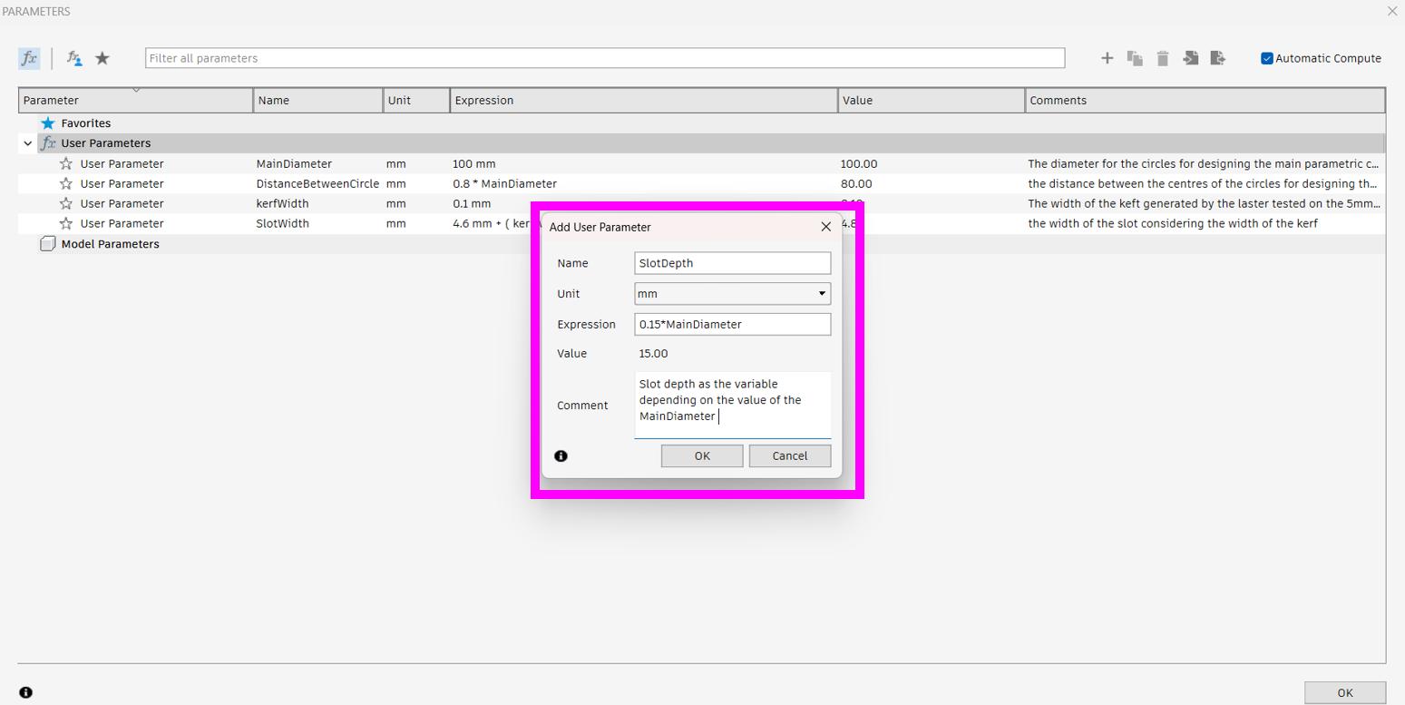
Defining Slot Depth.
-
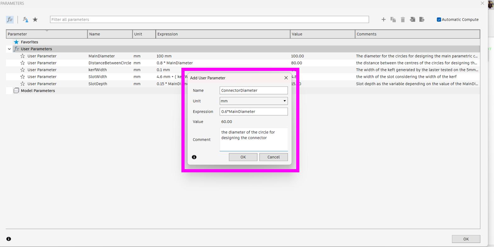
Defining Connector diameter.
-
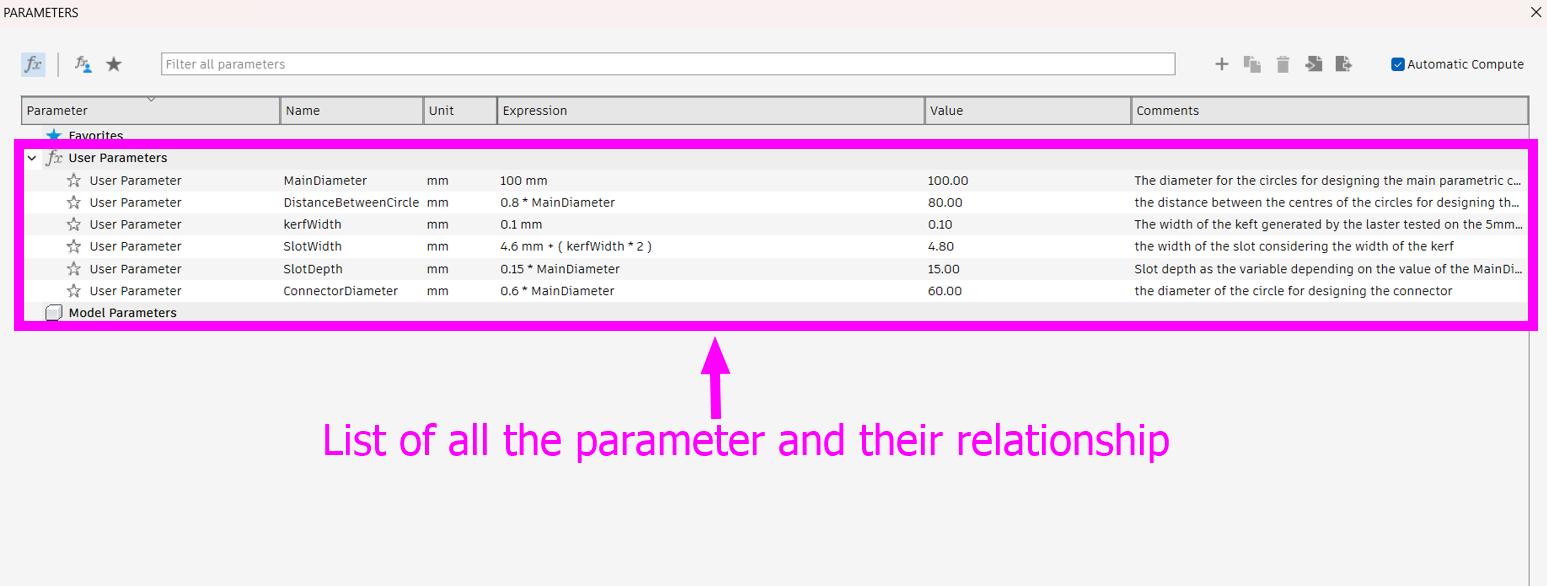
List of all the parameters defined.
-
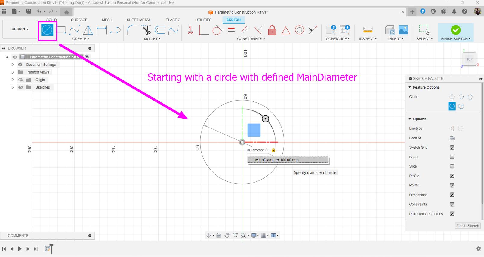
I started my design with a sketch.
-
Drawing a construction line.
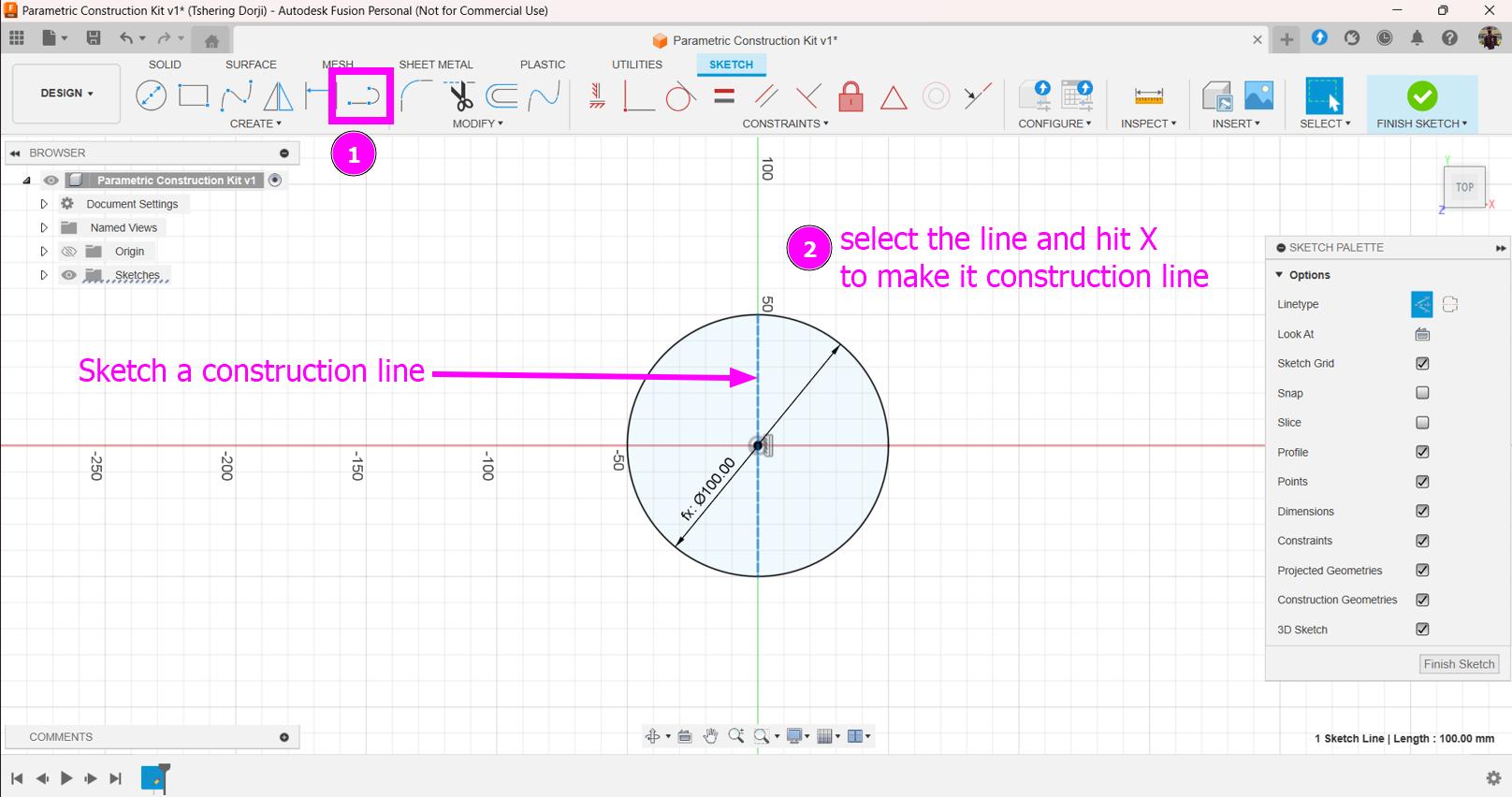
-
Dividing a circle into three equal parts using construction line.
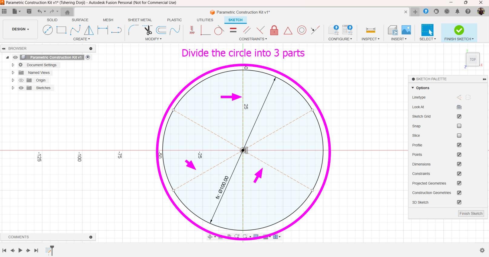
-
Drawing a line using defined parameter (DistanceBetweenCircle).
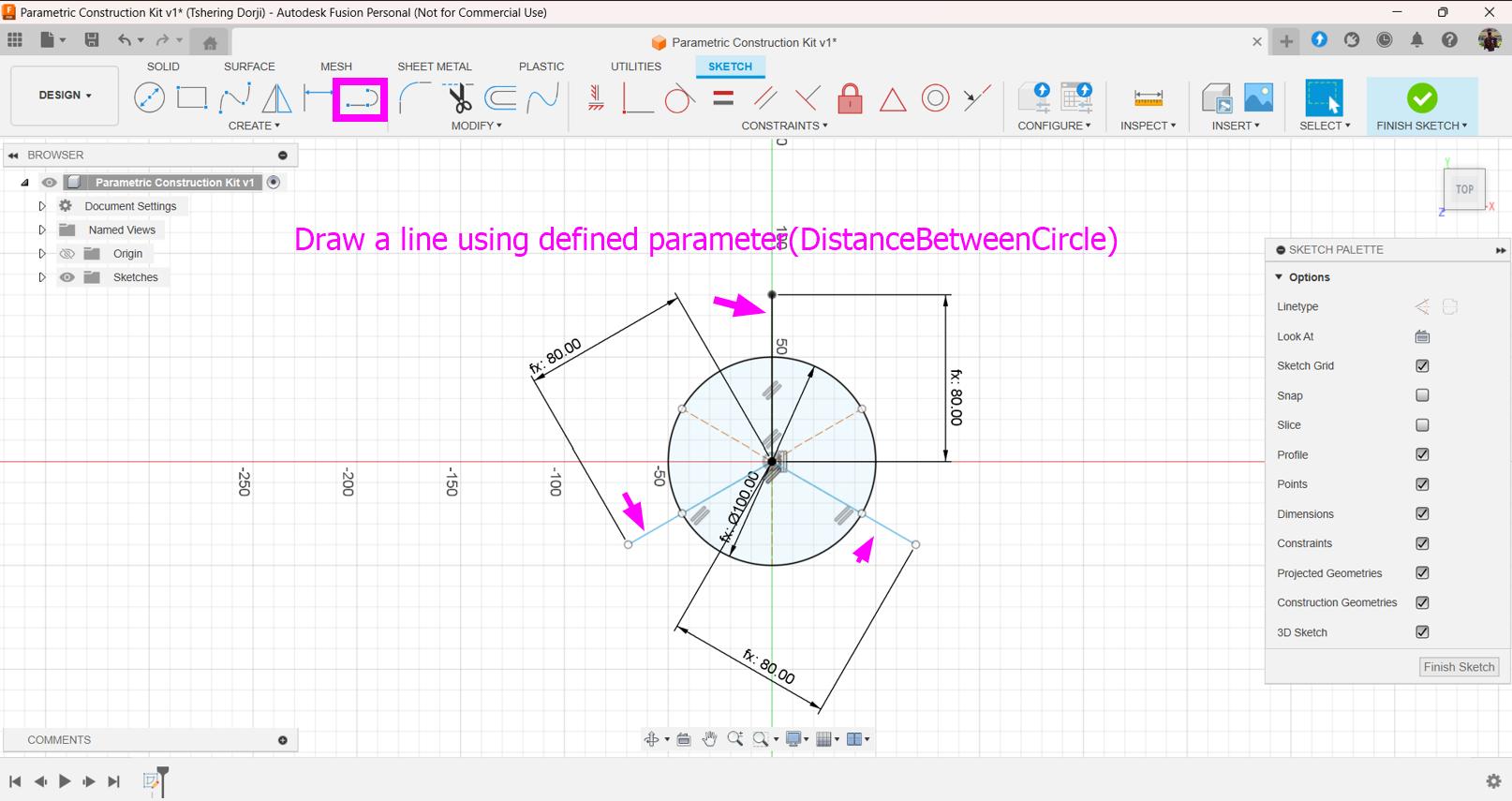
-
Adding three circles using defined parameter.
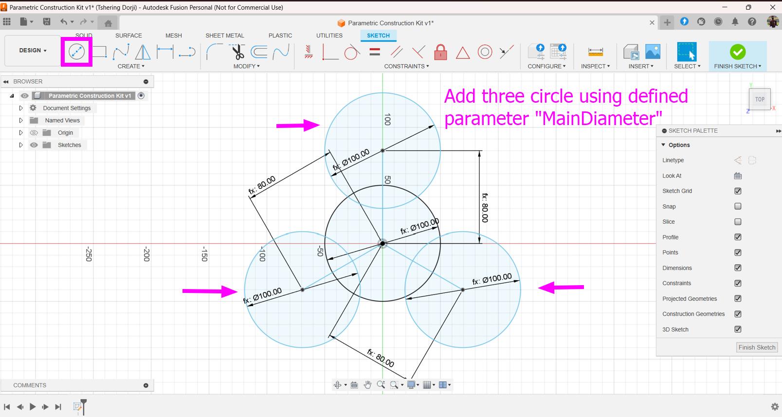
-
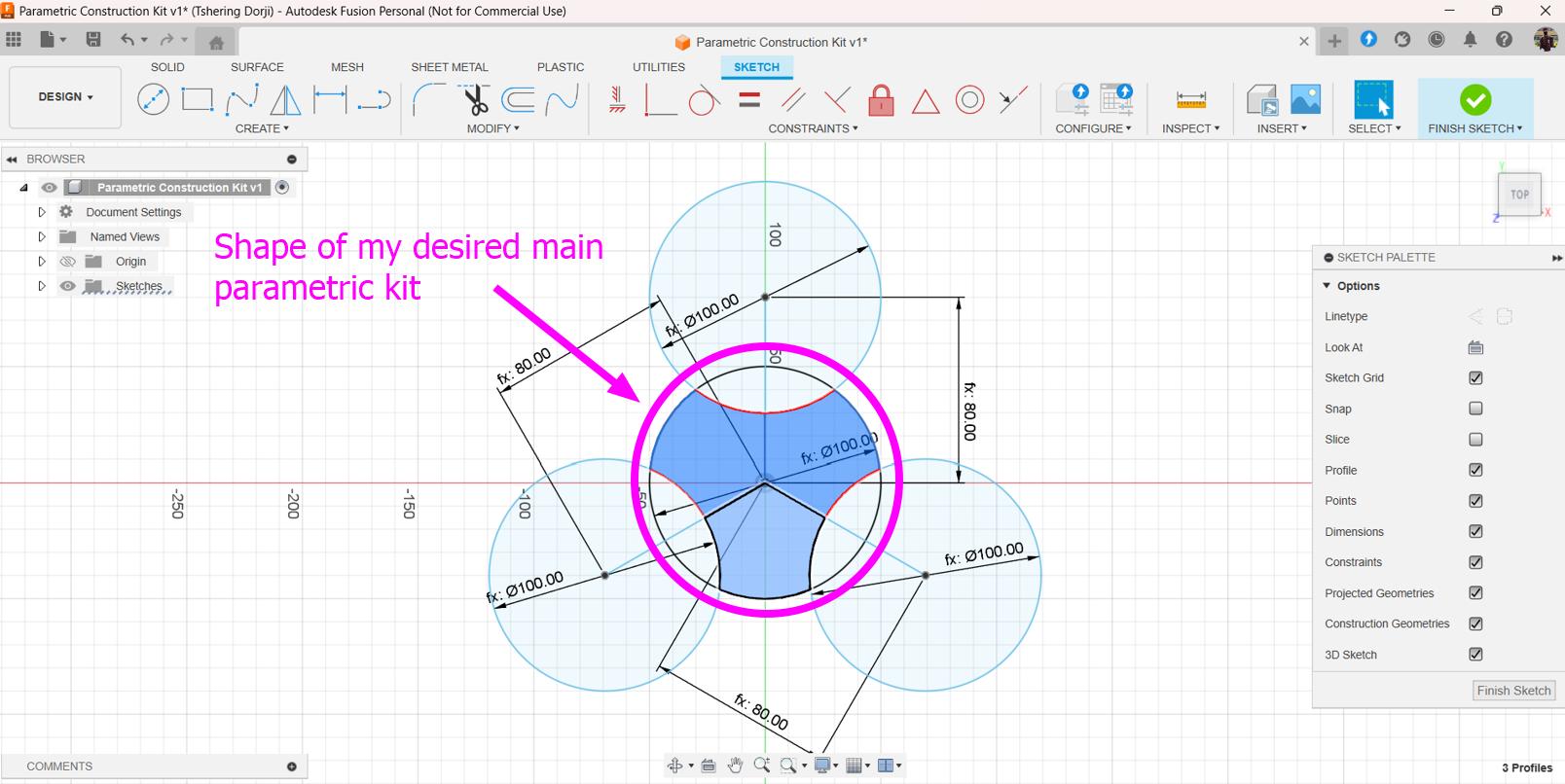
The shape of my main parametric kit.
-
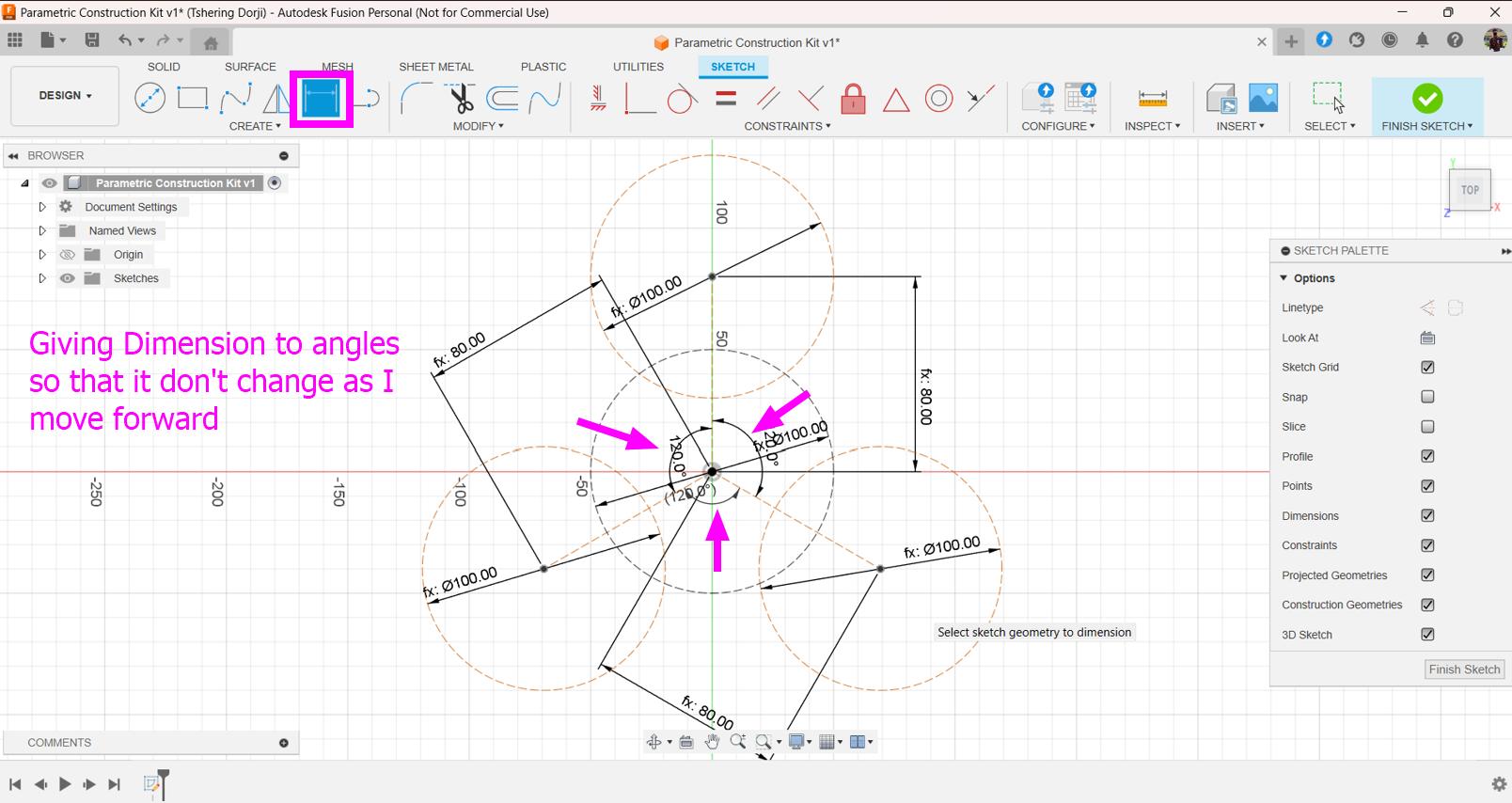
Give dimension to all the angle used in the sketch.
-
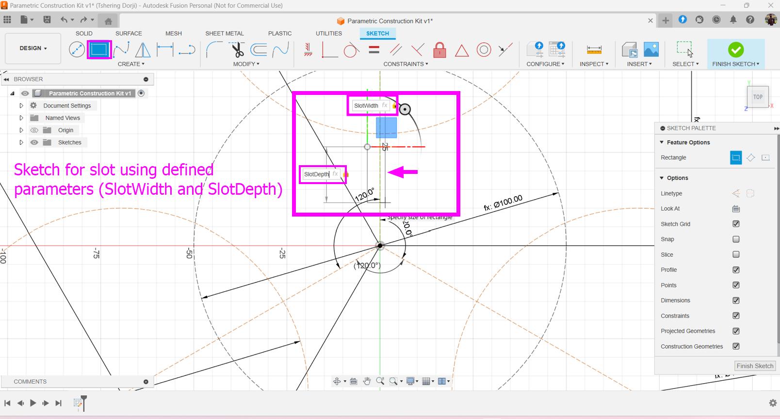
Sketch the slots.
-
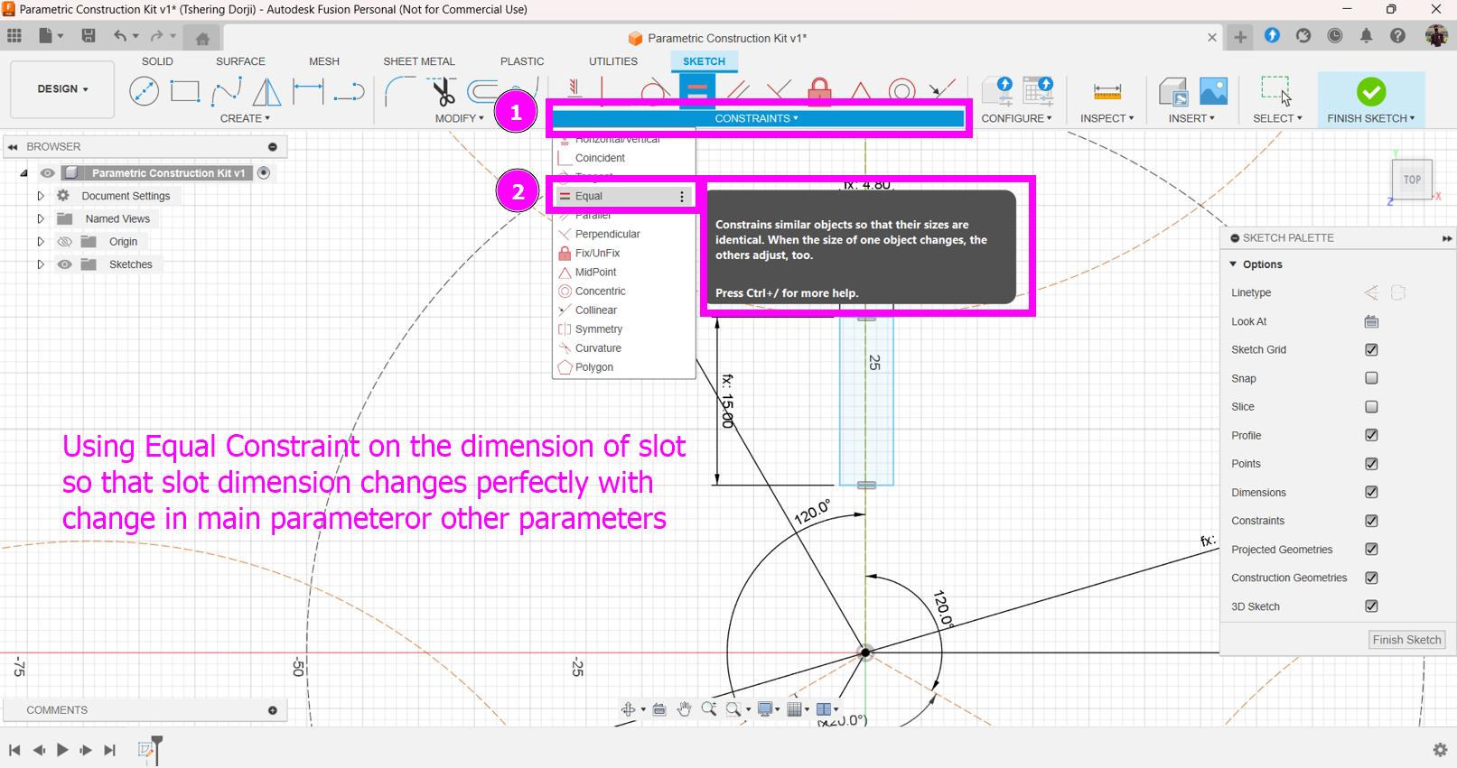
Using the Equal Constraint on slot.
-
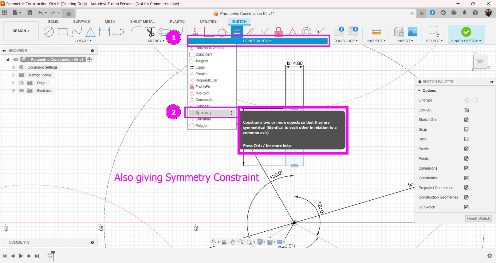
Symmetry Constraint on slot.
-
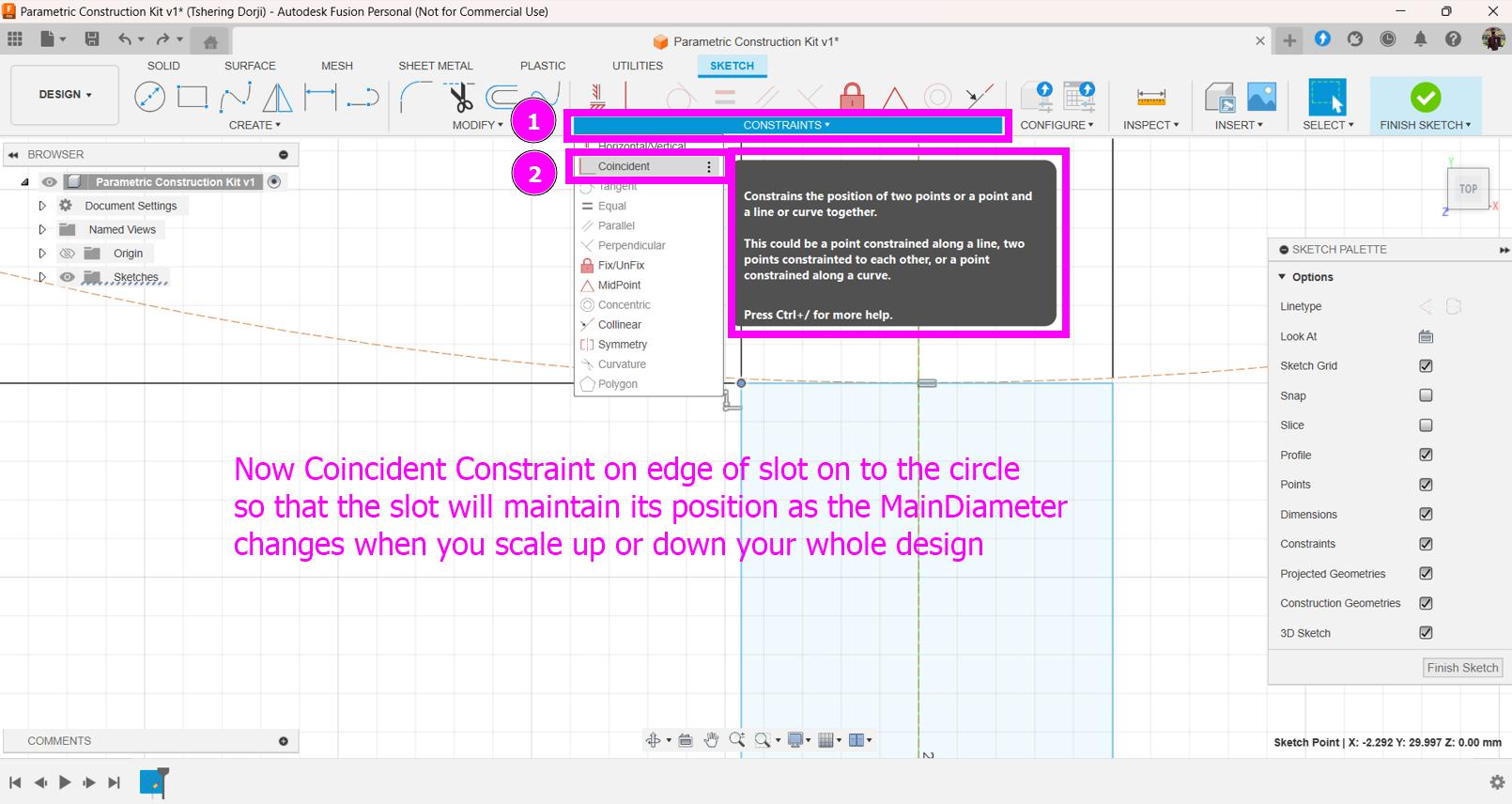
Coincident Constraint on the edges of slot and the circle so that they will change with respect to each other when I change the main parameter (which is the diameter of circle used for whole design).
-
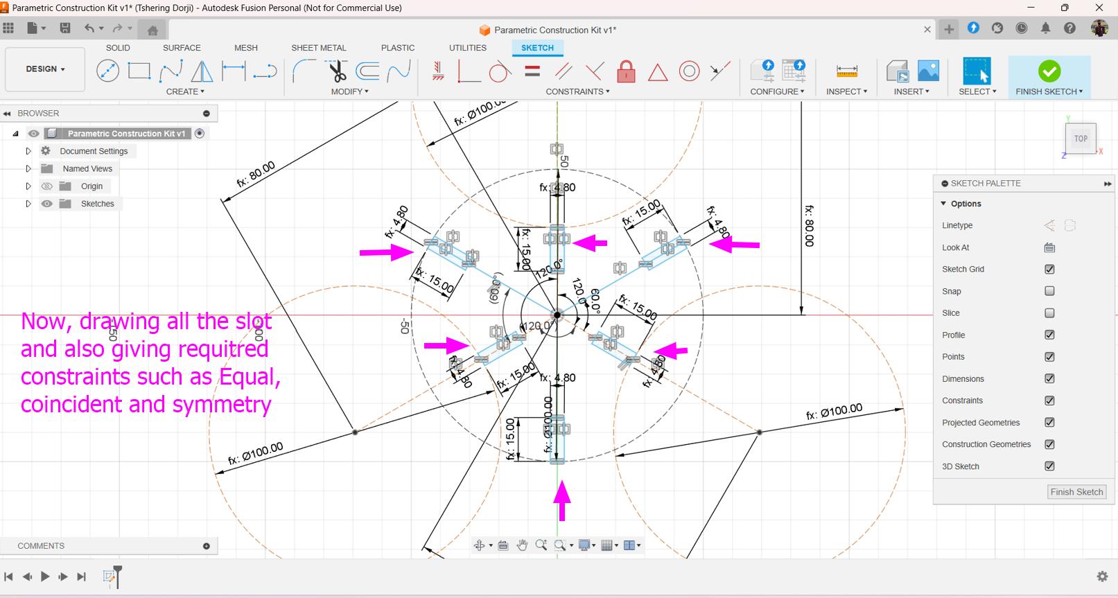
Similarly, sketch all the slots and constraint them.
-
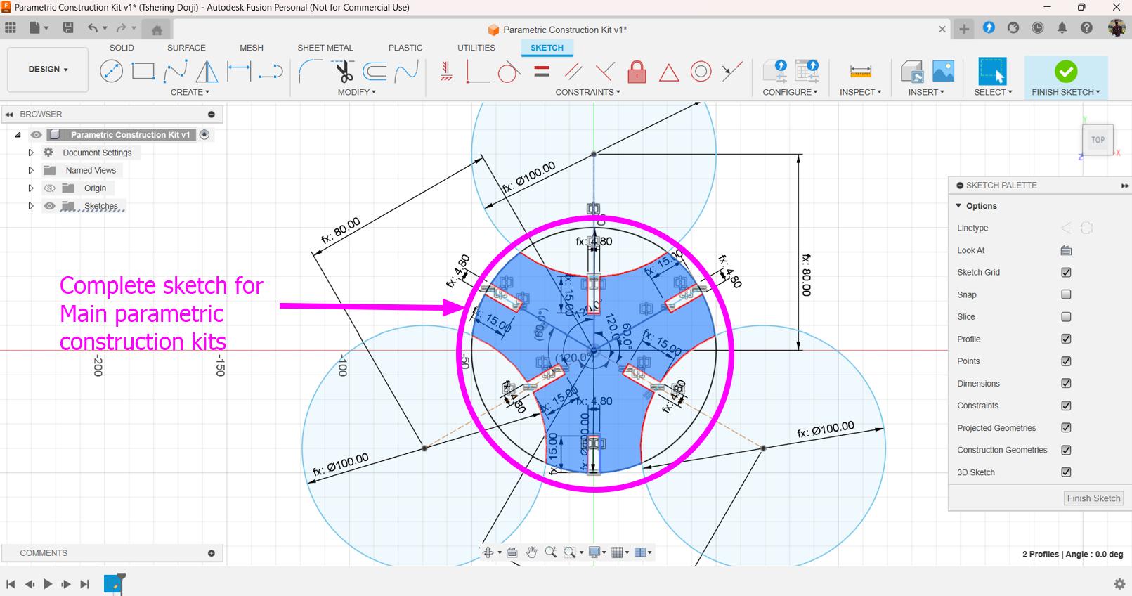
This is the completer sketch for my main parametric construction kits.
-
Sketch for connector of the parametric construction kits.
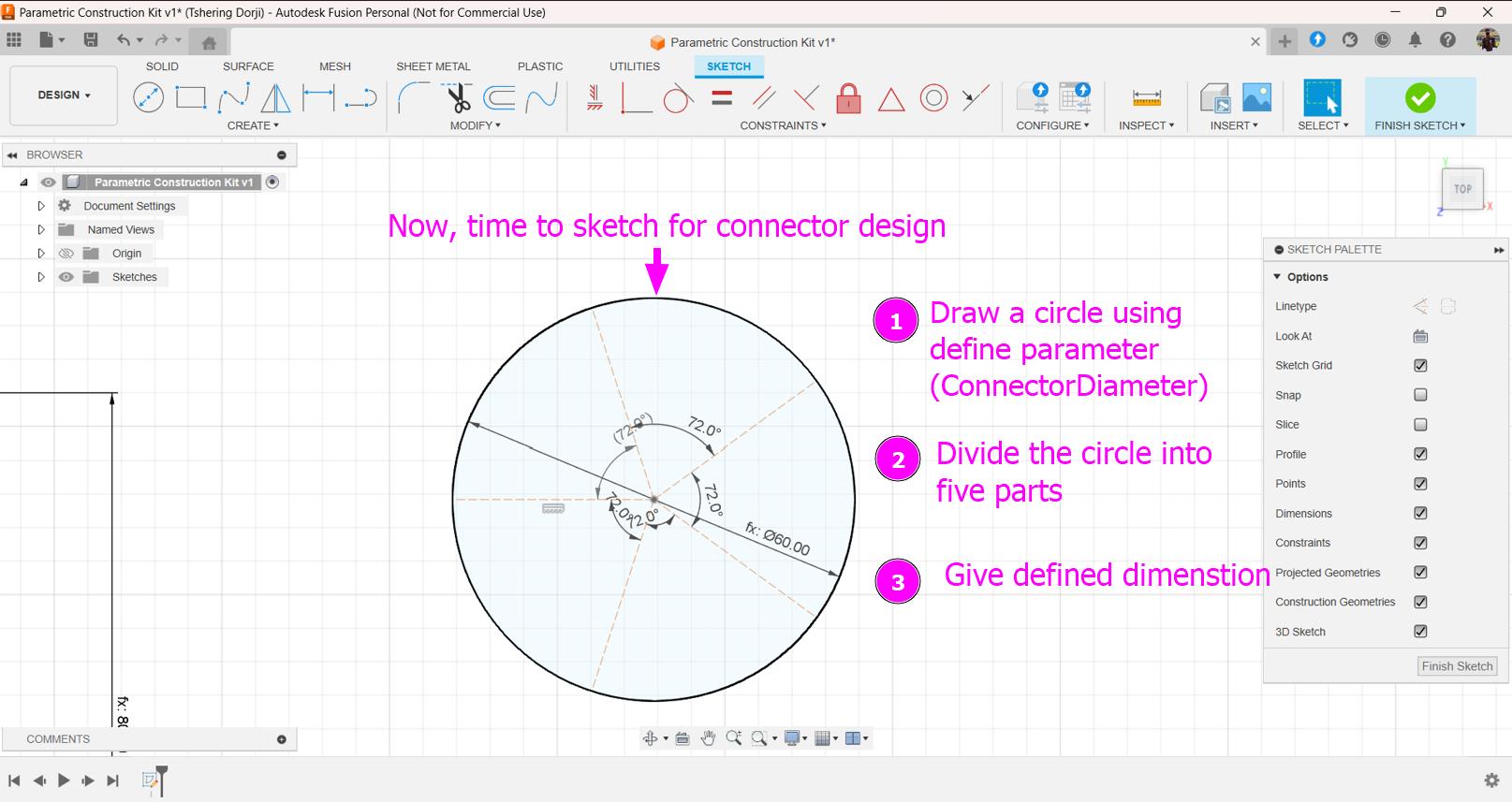
-
Designing a angled connector so that my parametric construction kits can form curve structures.
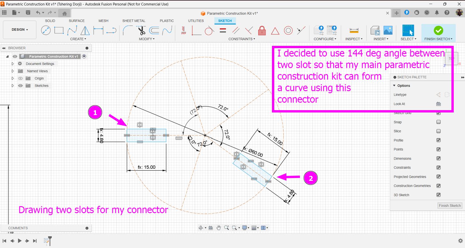
-
Sketch the slots and constraint them.
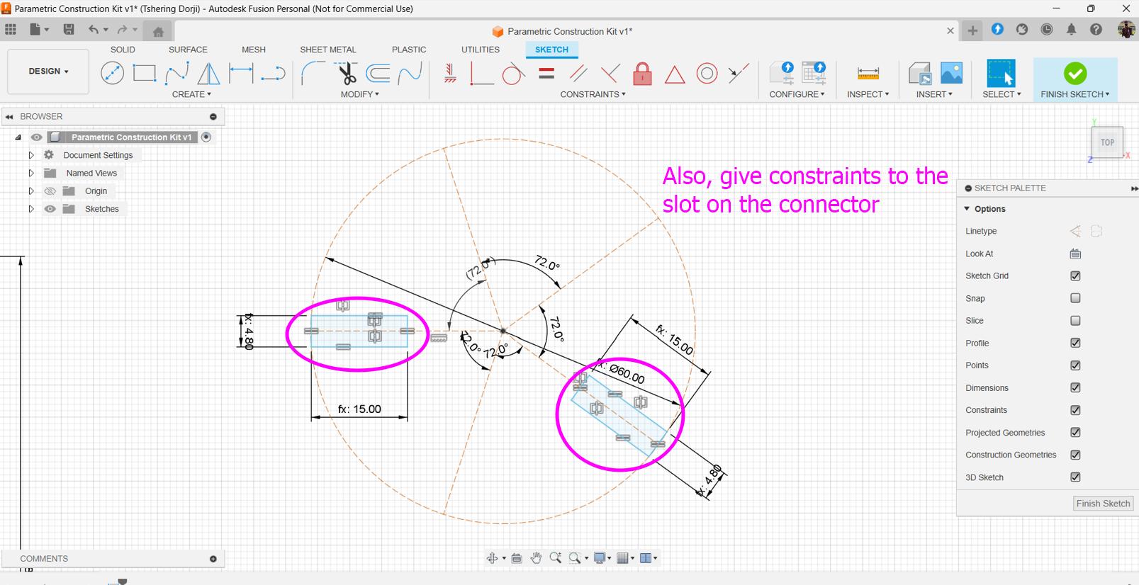
-
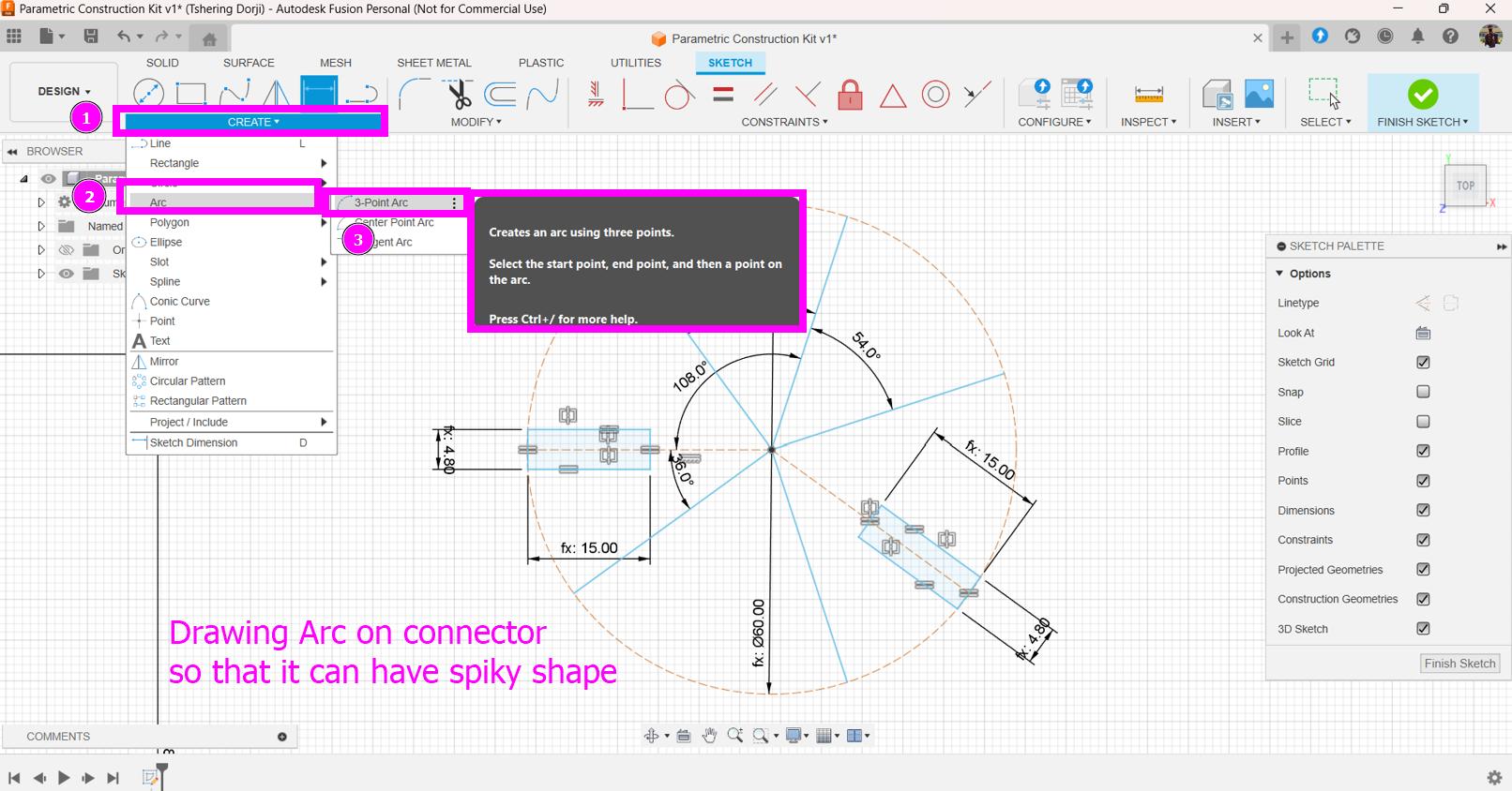
Dividing the circle using construction lines so that the lines can be used to sketch a shape for the connector.
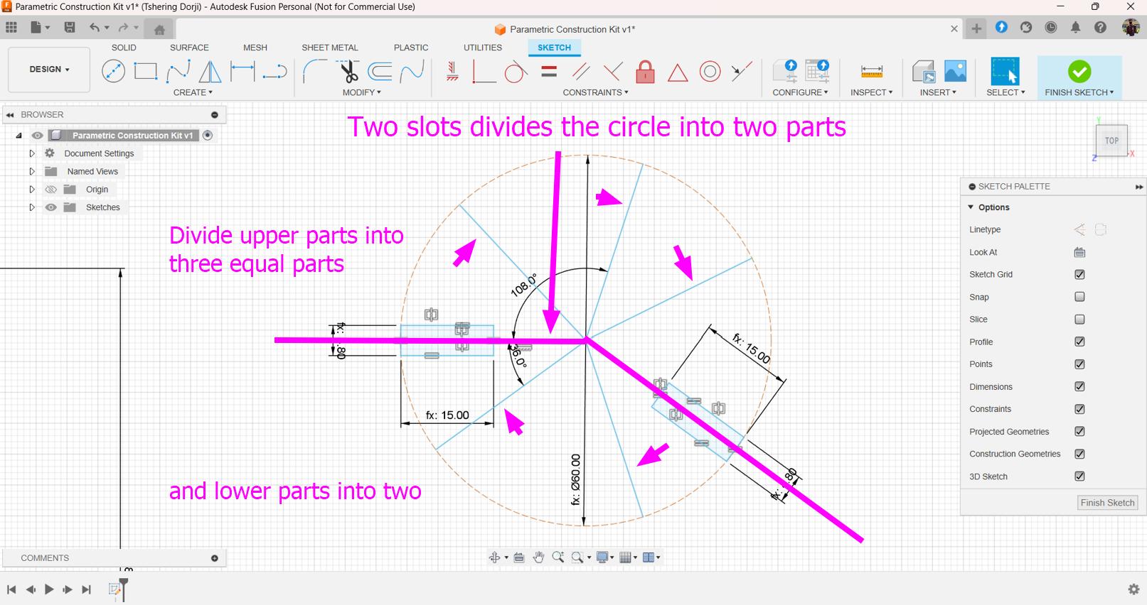
-
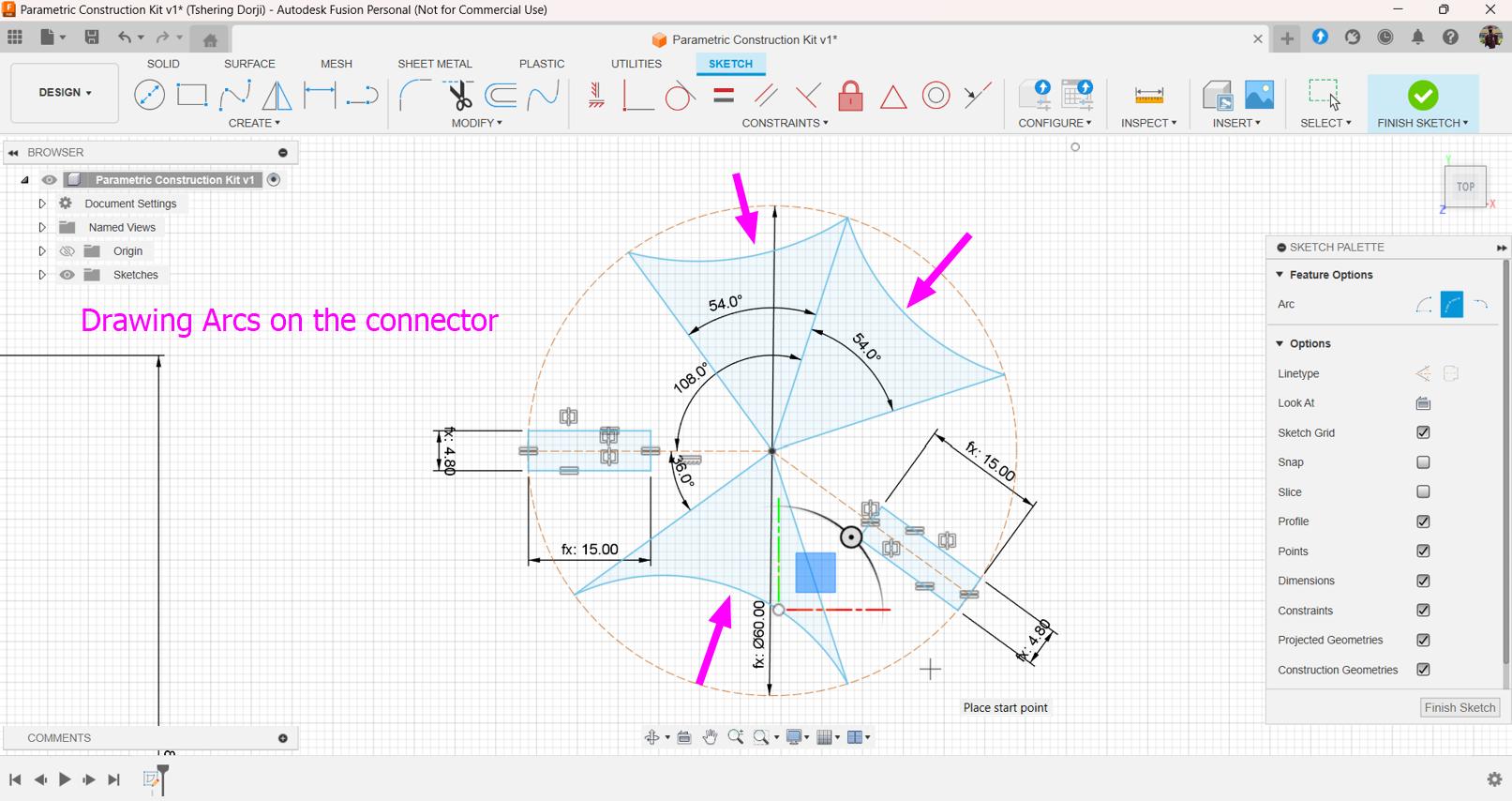
Using arch to sketch a shape for the connector.
-
Completed the sketch for the connector.
-
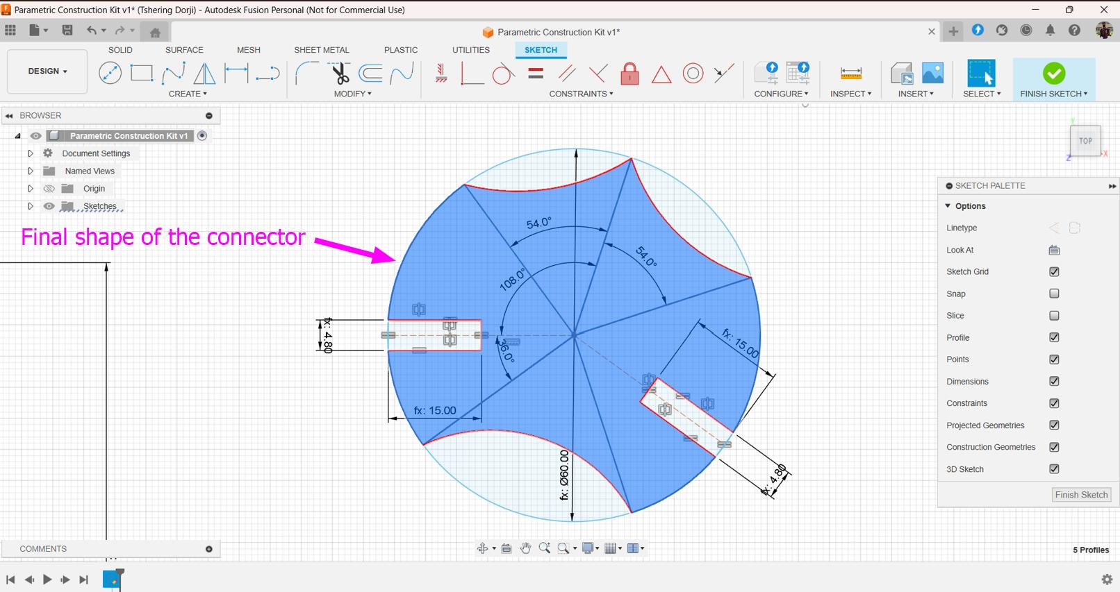
Here is the final shape for the connector!!!
-
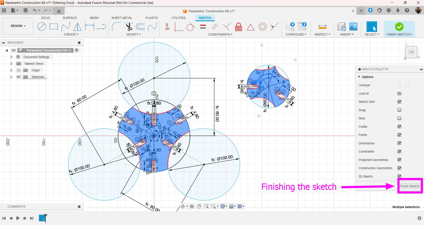
Finish the sketch.
-
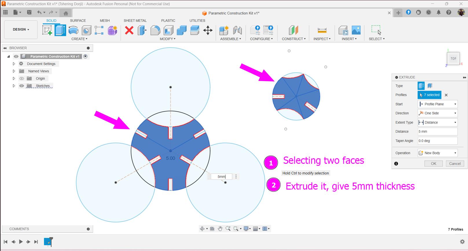
Extrude part of the sketch that you plan for your parametric construction kit.
-
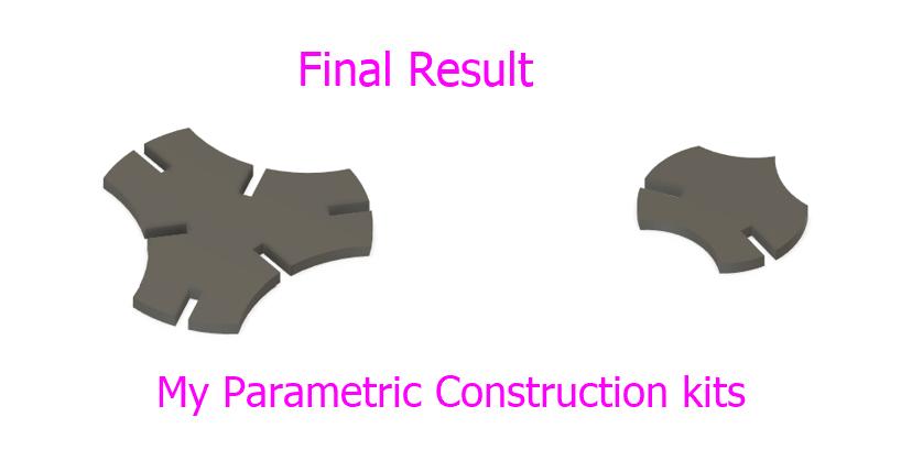
Design for my parametric construction kits is completed.
-
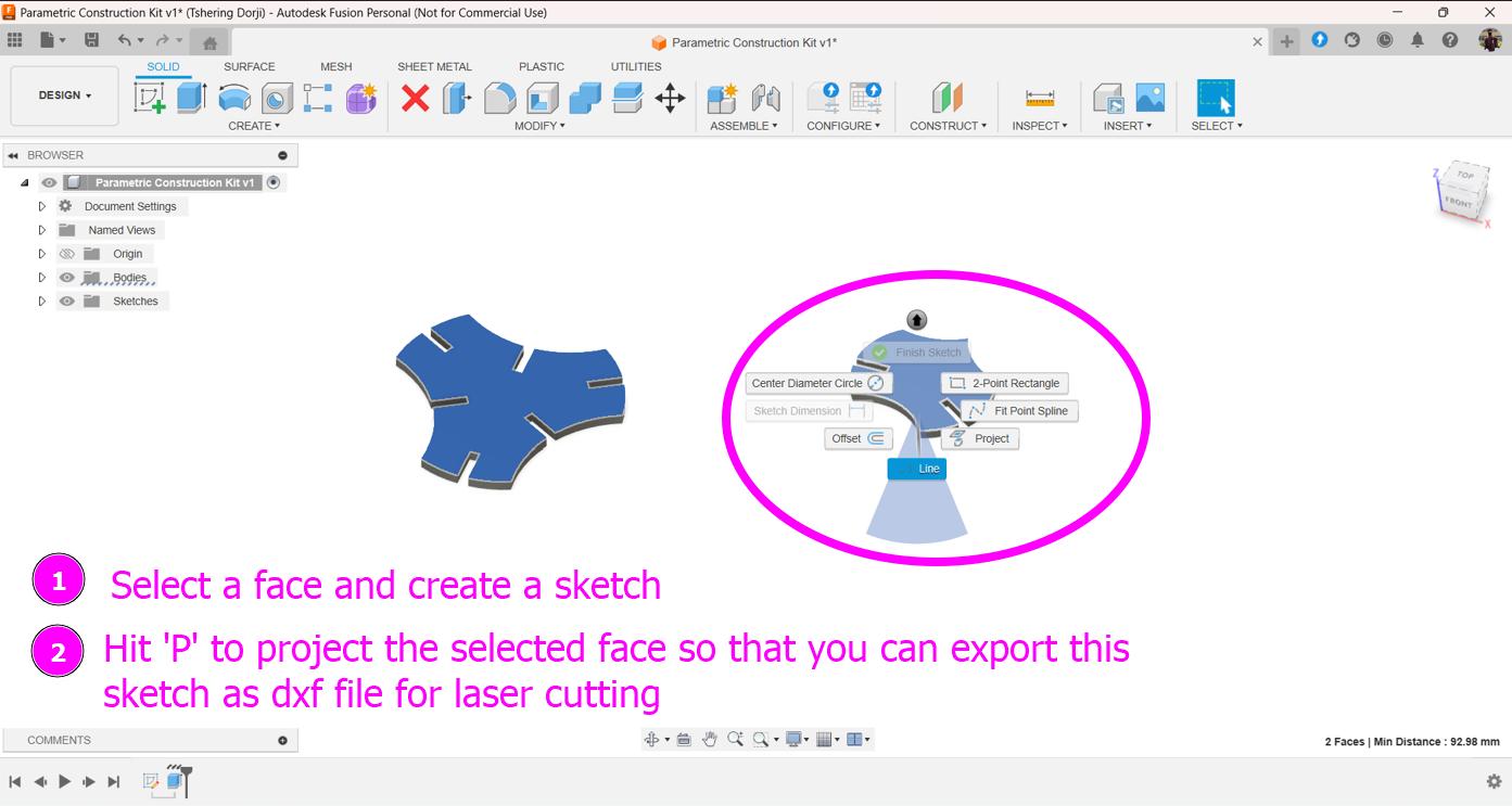
Since, I cannot directly export all my sketch or face of the design, I found out I can actually project the required face of the design and create new sketch which can exported as dfx file for laser cutting. Create a new sketch, select the required faces and project them.
-
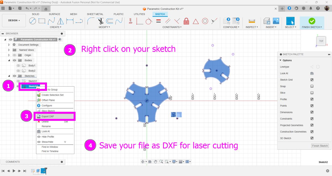
Select the sketch which is created earlier using projection and export it as DXF file for laser cutting.
Laser cutting the designed Parametric construction kit on Trotec Speedy 100 Flex:
- Turn On the machine. Turn the Key Right side (Ensure the lid of the laser is closed).
- Open the lid once you hear the beep sound.
- Machine will beep once its done with homing and starting up
-
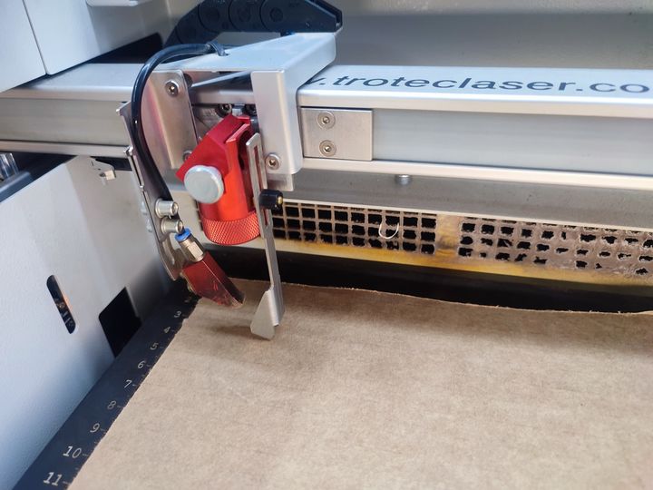
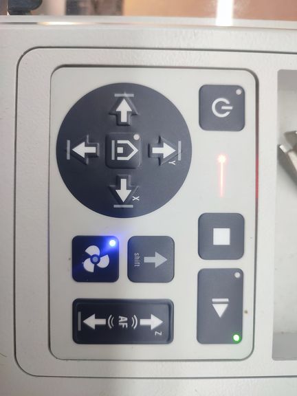
Place the work piece to the left corner of the bed. Move the nozzle to the middle of the work piece to set Z axis or Use the autofocus button to set the Z axis.
-
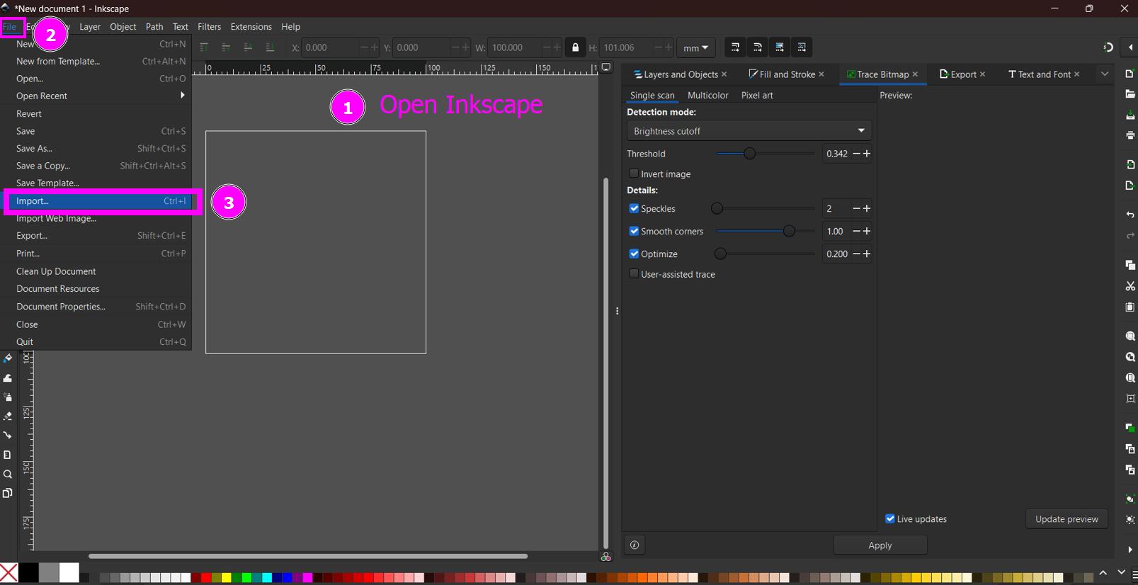
Open Inkscape.
-
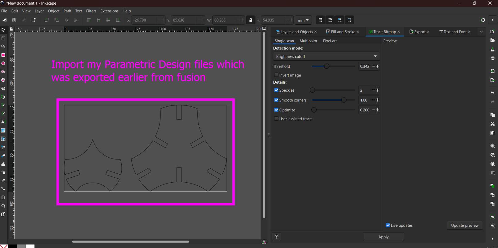
Import your parametric construction kits design file into Inkscape.
-
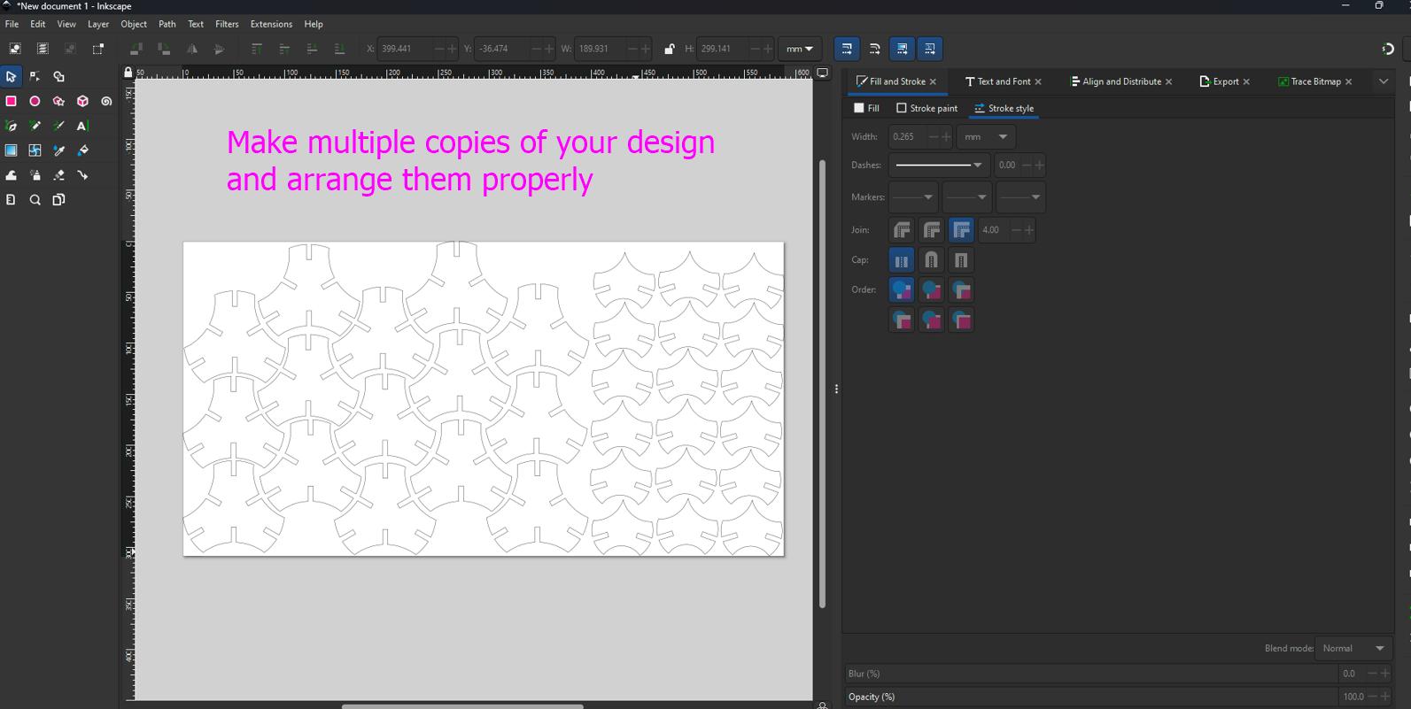
Make multiple copies of your kits and arrange them properly so that you can reduce wasting cardboard.
-
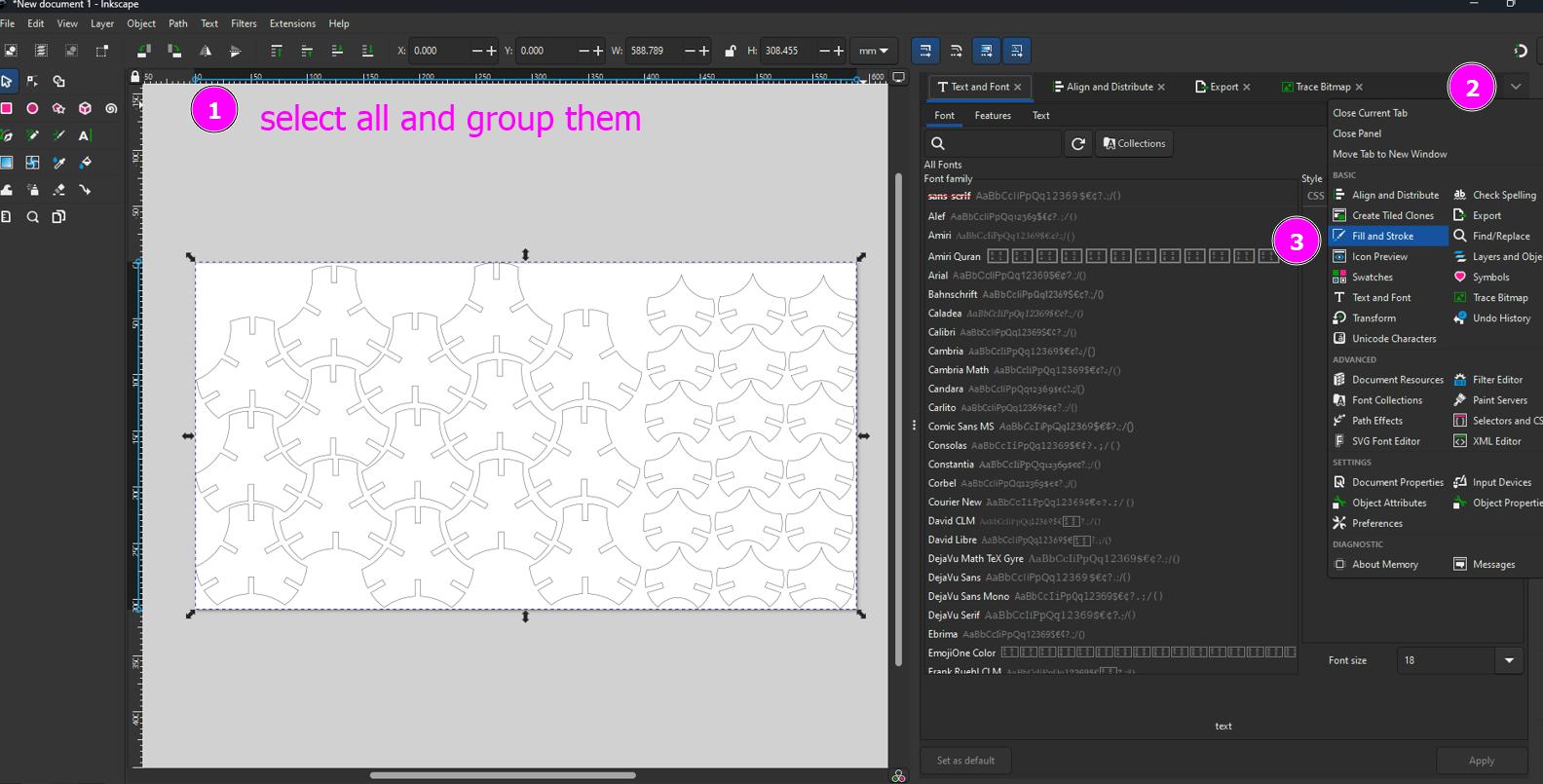
Select all of them and group them.
-
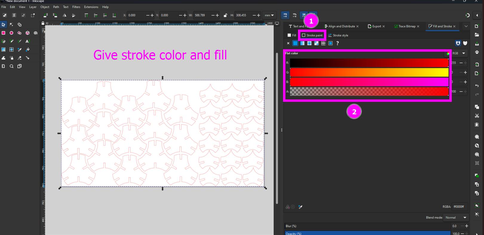
Give stroke color and fill.
-
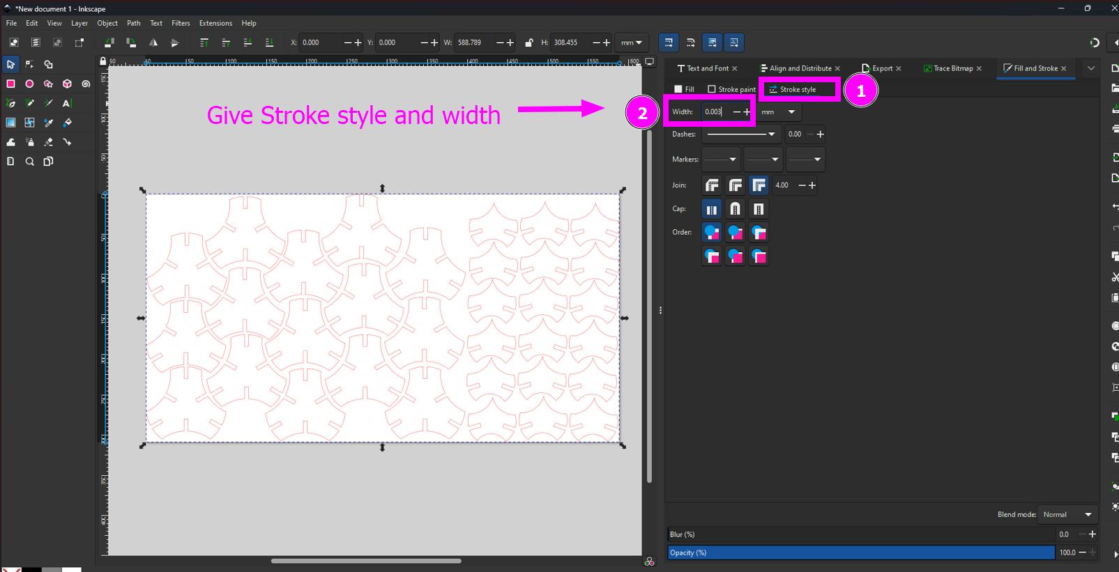
Specify stroke color and size of the design so that your laser cutter can cut your design properly. By default the black color will be engraved and red color will be cut. Make sure you set the proper stroke width and style.
-
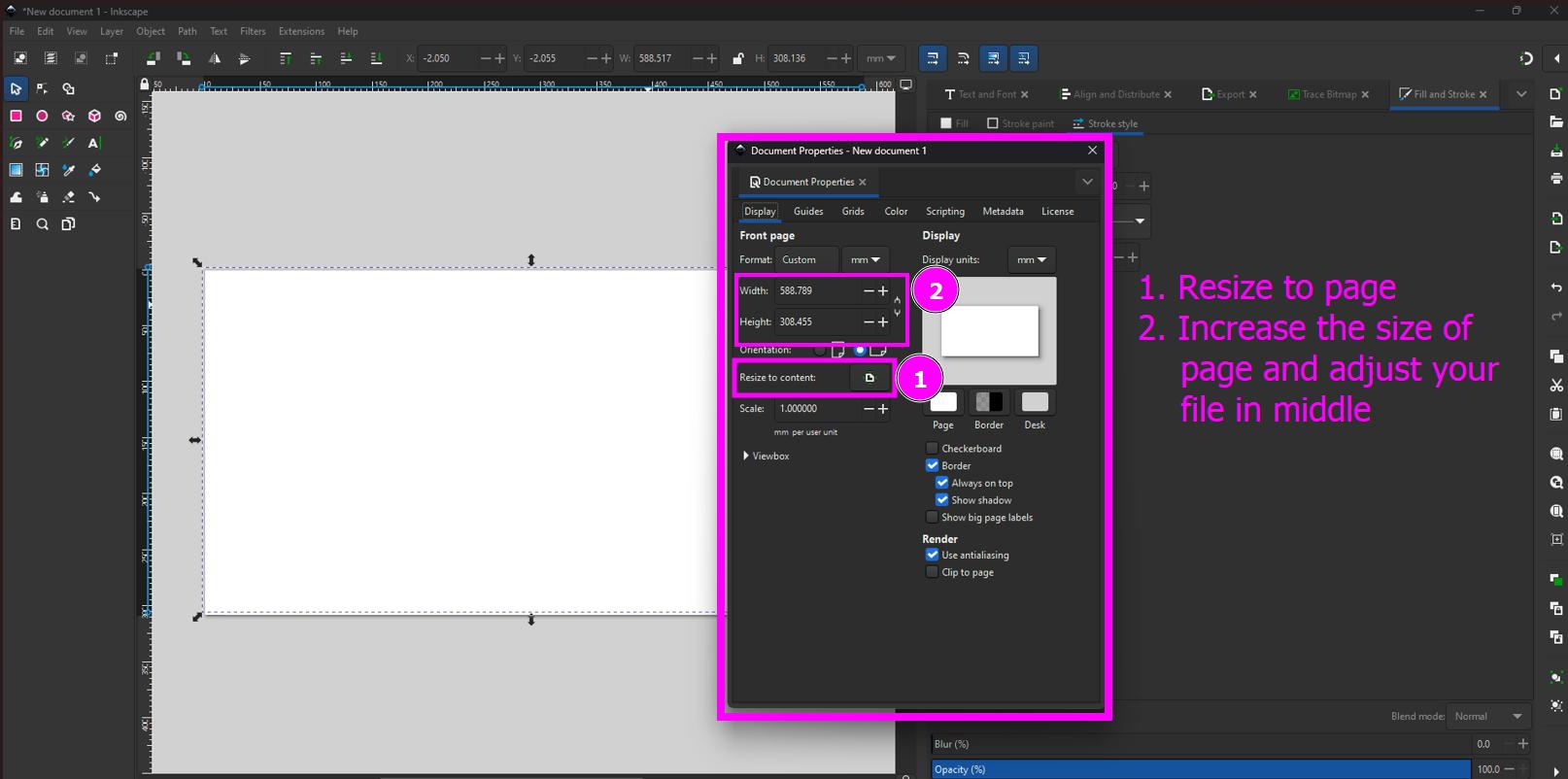
Adjust the size of the page and position your design file in the middle of the page.
-
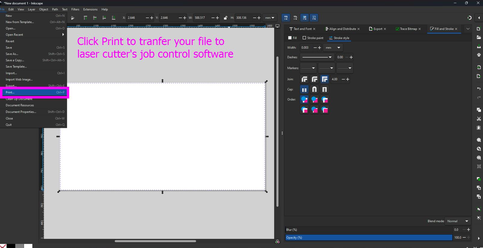
Ctrl + P to transfer your design to your laser cutting software interface.
-
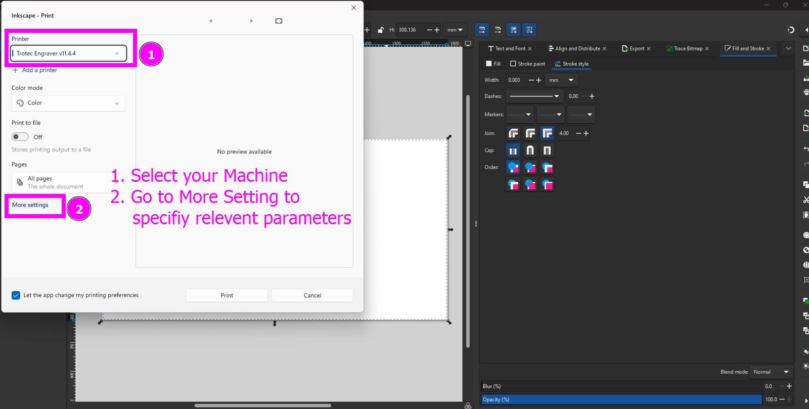
Your laser cutter will be detected by the computer, select the machine and click print.
-
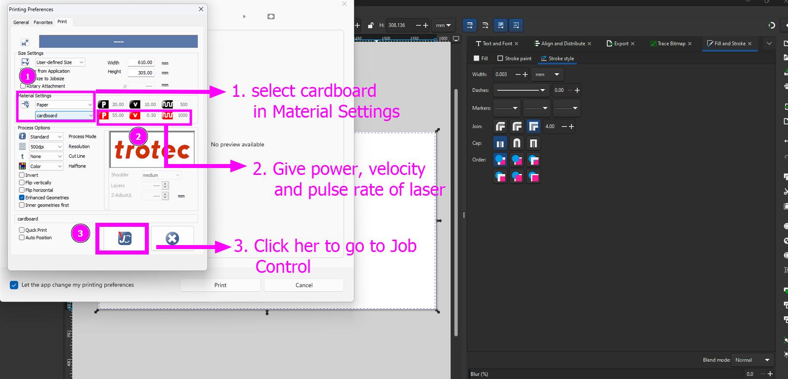
Specify the material (cardboard in my case) and also give right power, pulse rate and velocity as tested in group assignment.
-
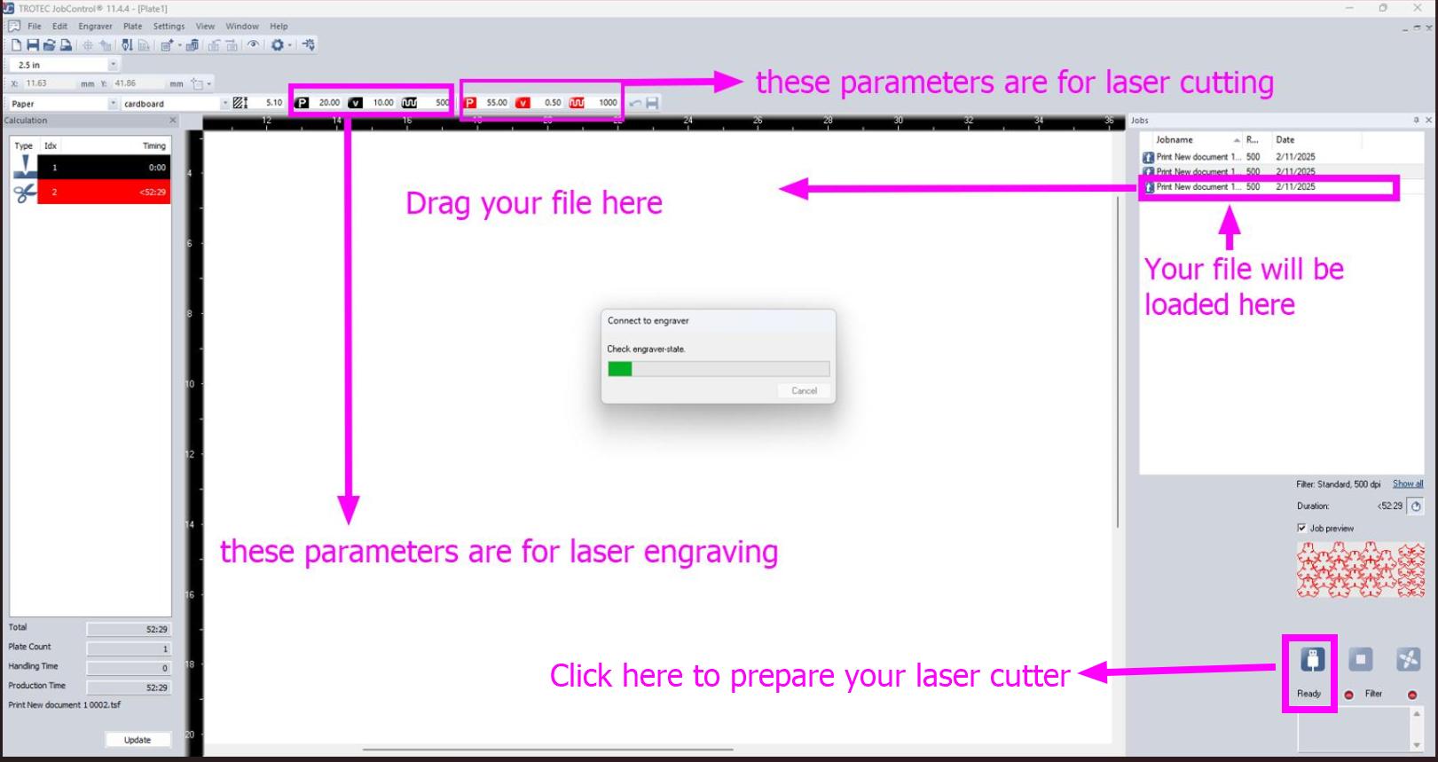
Now, go to the Job control interface and your design file will be automatically loaded there. Drag your file and cross check everything. Once checked, start laser cutting. Always remember to stay right next to laser cutter to stop the machine if something goes wrong as it could start a fire.
-
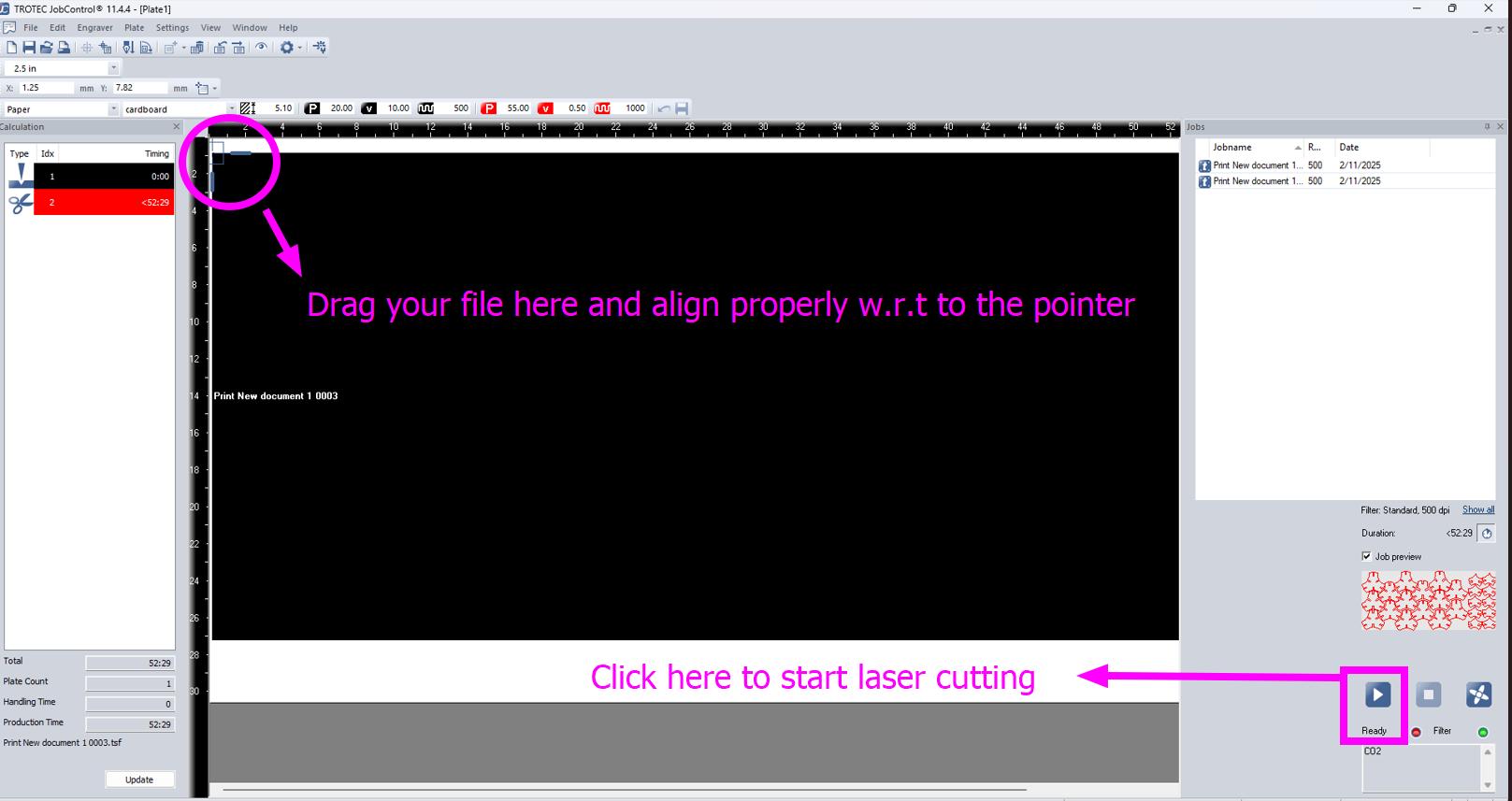
Drag your loaded file in the main bar of the interface for laser cutting.
-
Put some weight on your card board so that it will not move during laser cutting and also remember that the weight should be be on areas of card board which will be laser cut.
-
Manual Z calibration.
-
Use z control button for z calibration.
-
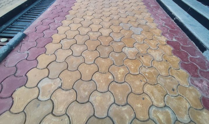
The design inspiration for my parametric construction kits.
-
Successful Laser cutting.
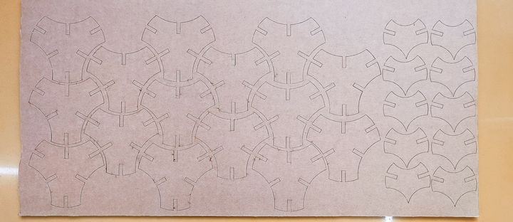
-
Taking out the kits from the card board.
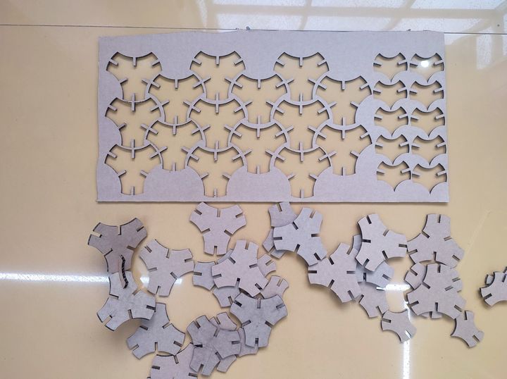
-
Foot path.
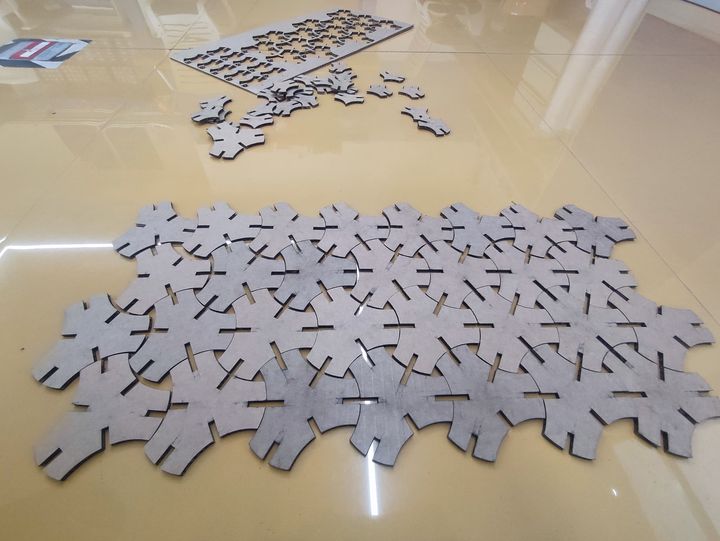
-
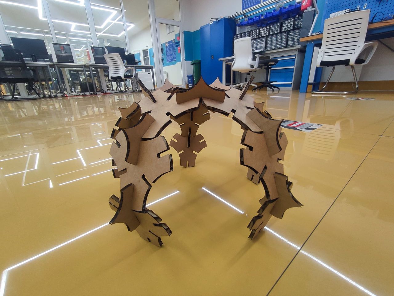
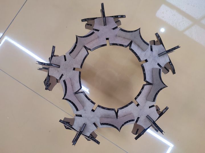
Dome constructed out of my parametric construction kits.
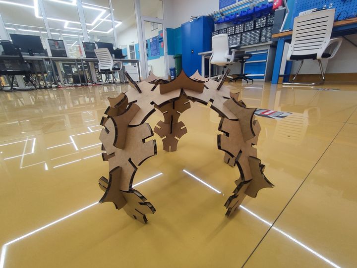
-
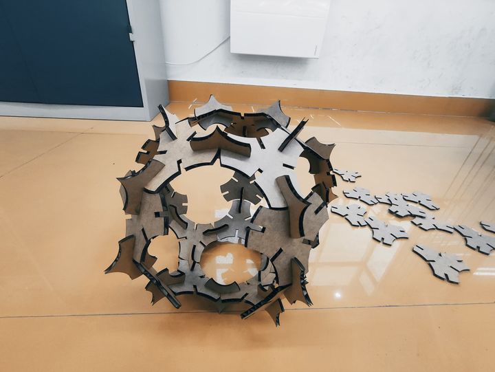
Spiky Ball.
-
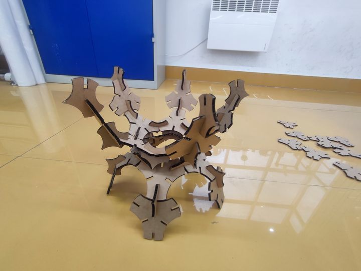
Another assembly.
-
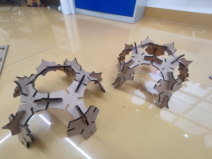
More Assembly.
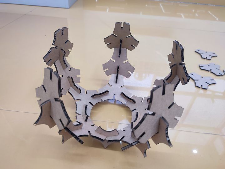
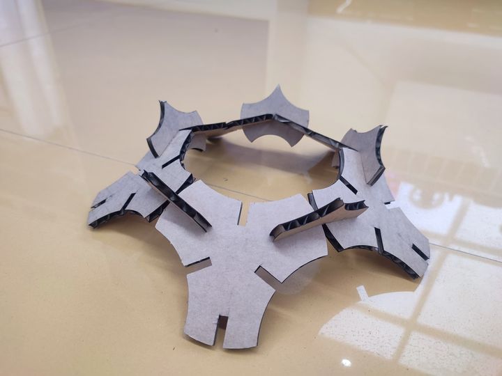
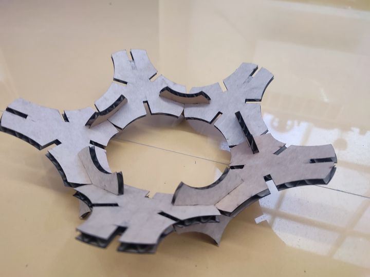
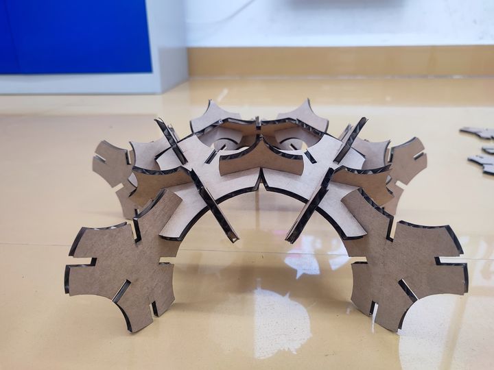
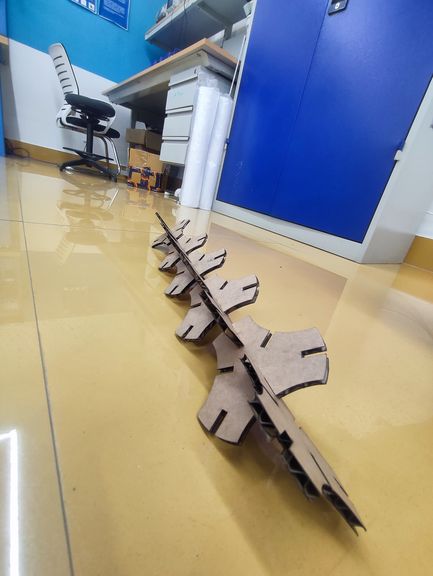
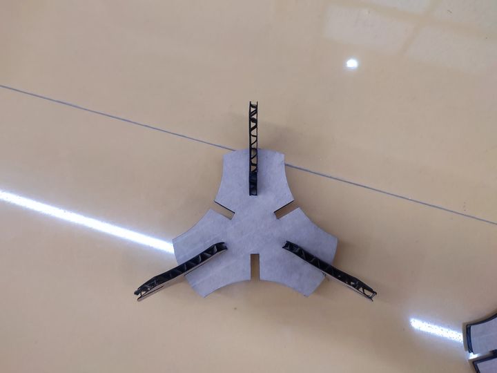
-
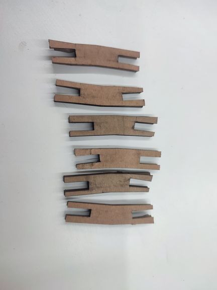
This is the first connector I designed. After laser cutting, I tried to assemble the construction kits but the connector was quite weak and I could do much with that connector. So I designed the new connector which is show above.
Sticker Cutting on Vinyl Cutter
-
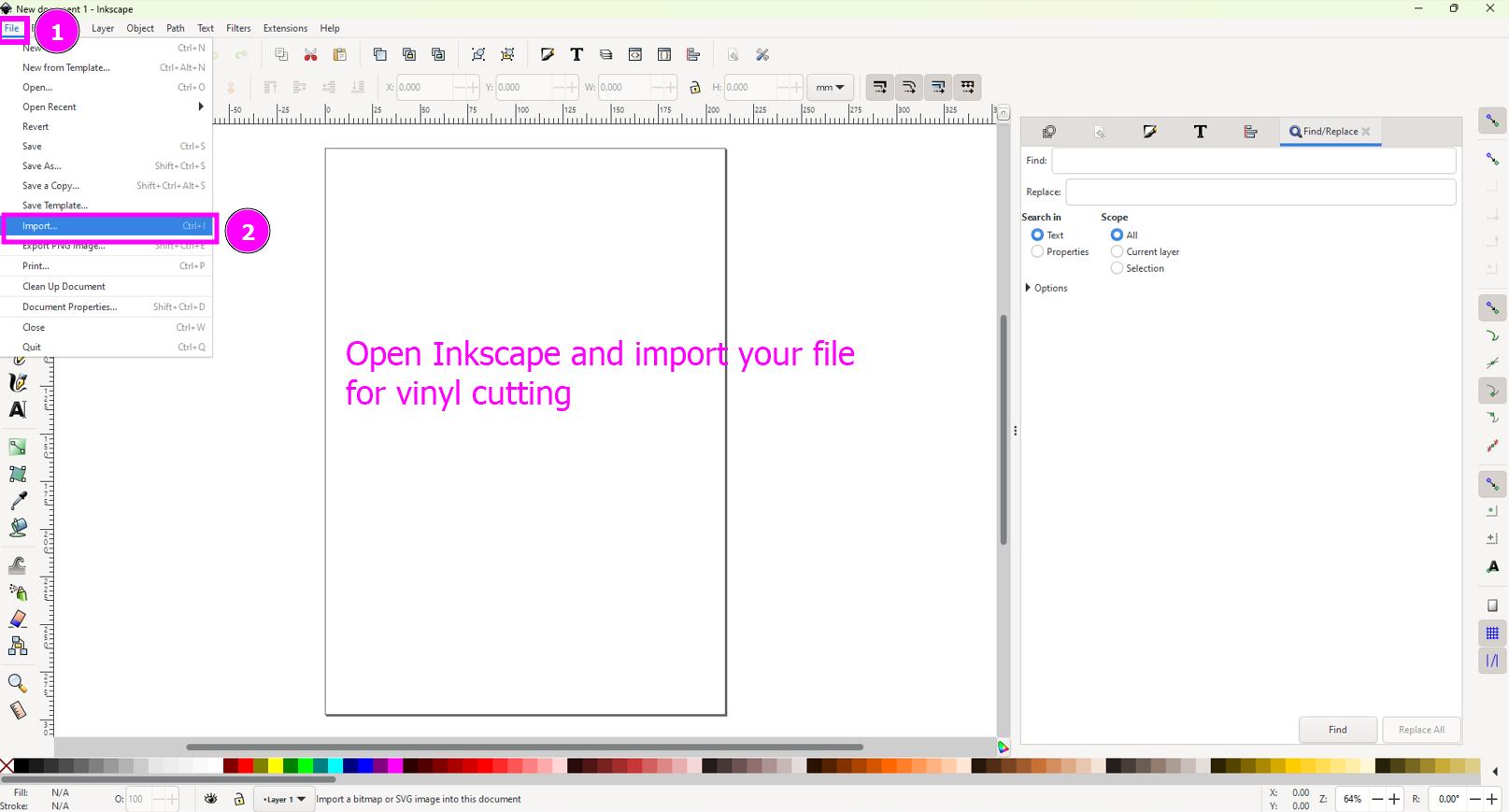
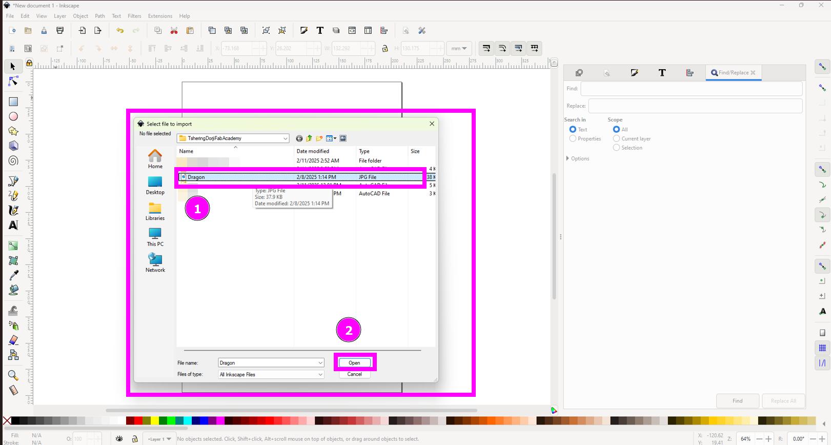
Open Inkscape and Import file for vinyl cutting
-
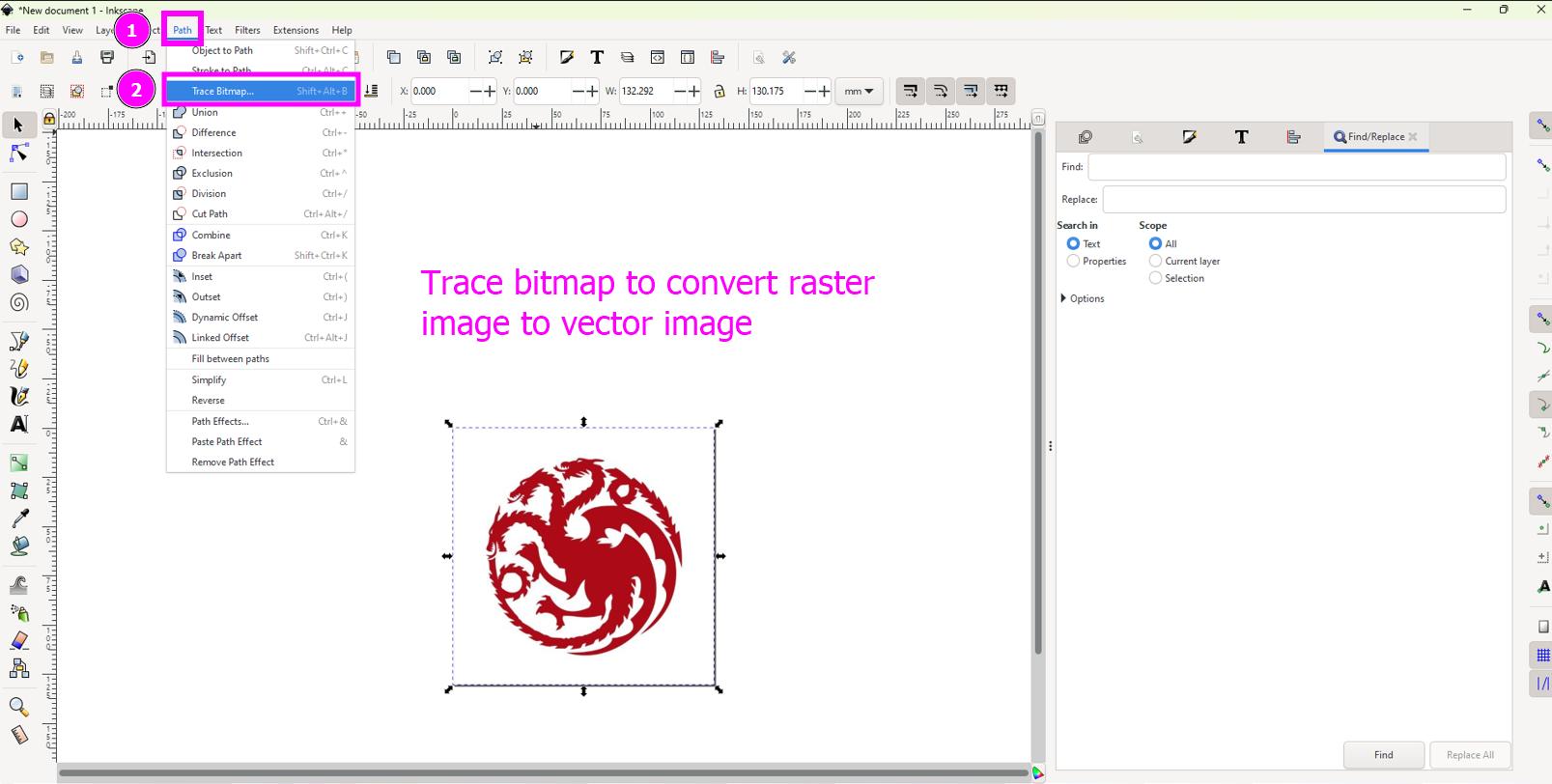
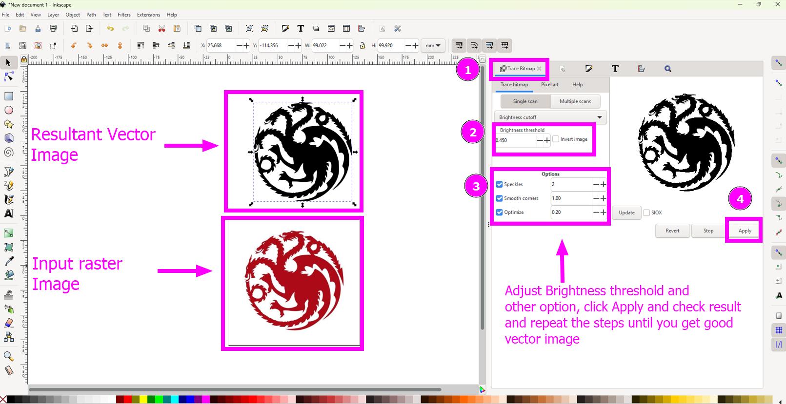
Convert raster image to vector image
-
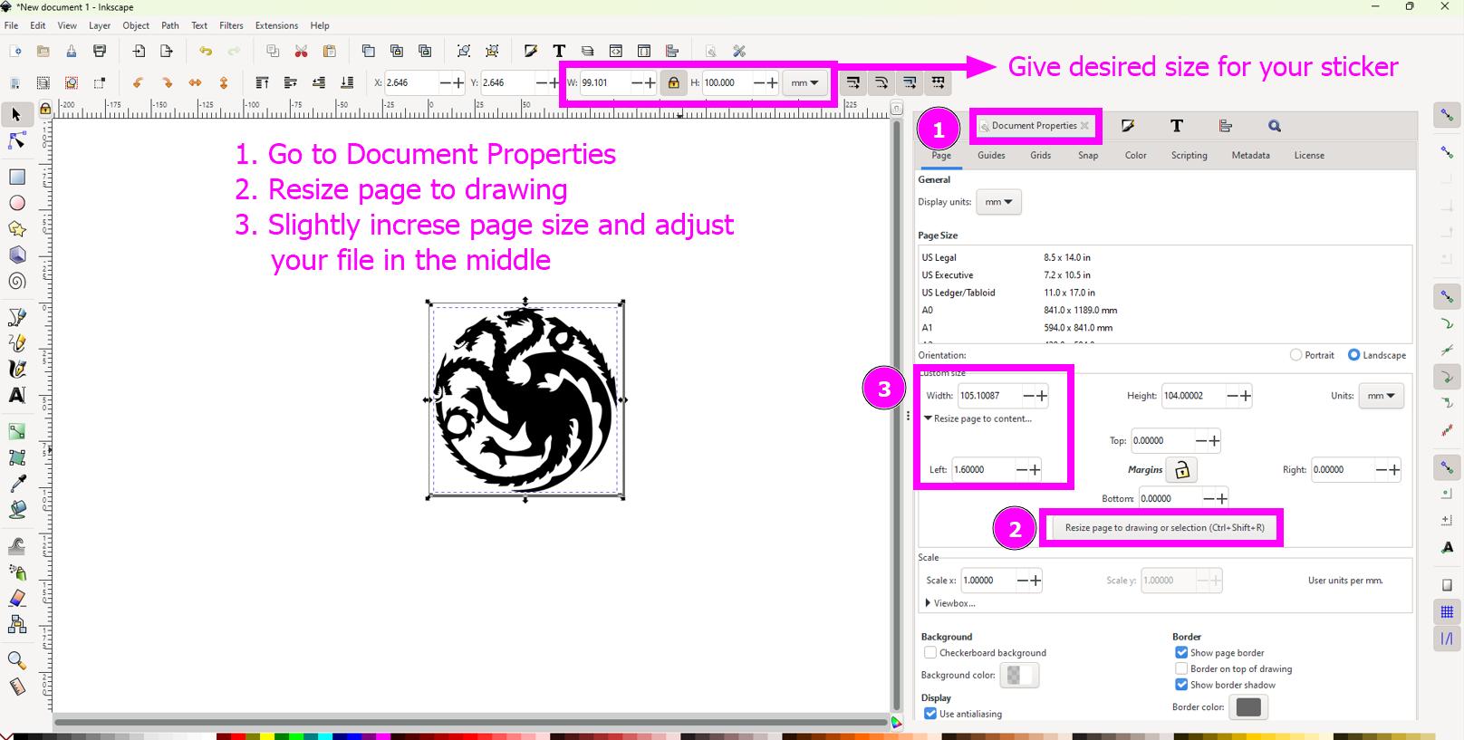
Resize to page and align it properly
-
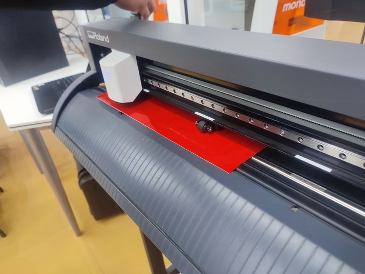
Start vinyl cutter and put the sheet( I used red piece).
-
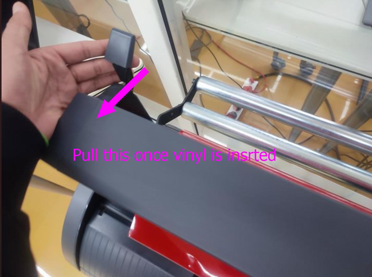
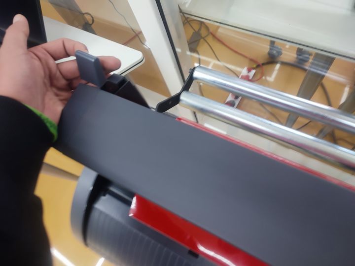
Secure it by pulling the handle.
-
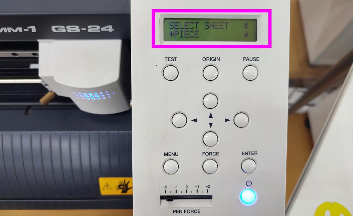
Chose piece and click enter so that the machine will measure the size of the piece you just loaded.
-
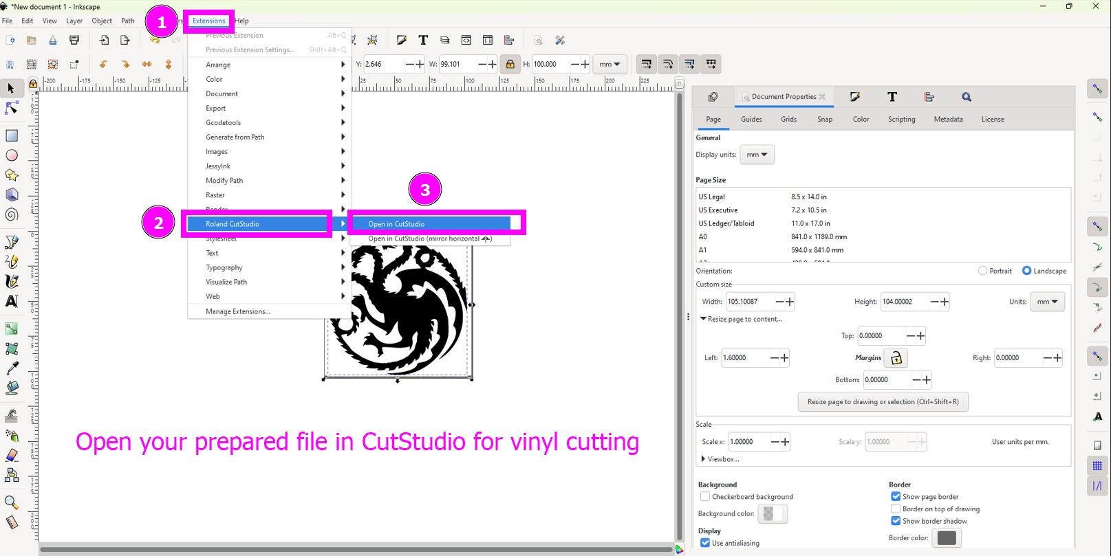
Jump back to Inscape, click Extension and select your machine to transfer your file to vinyl cutter Software.
-
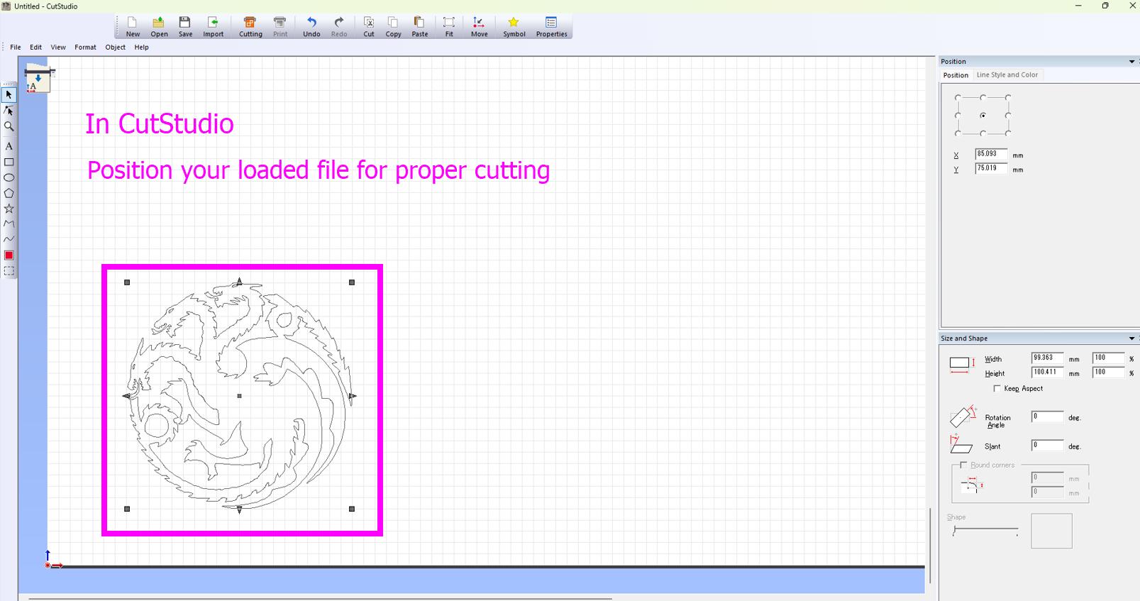
Position your design.
-
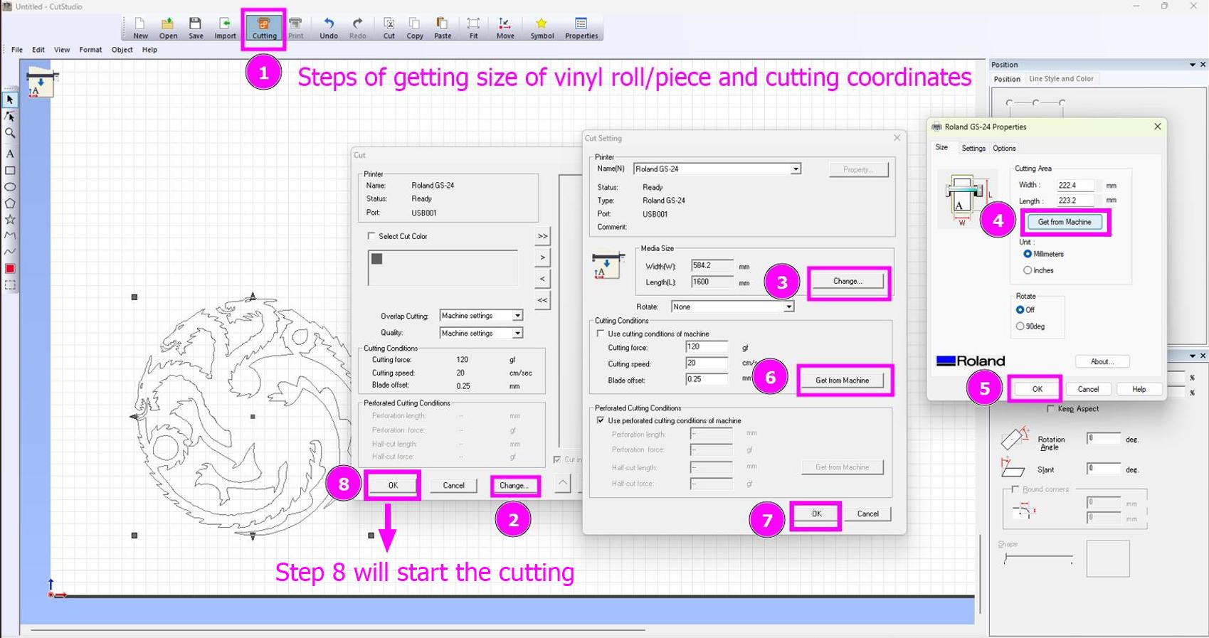
Get the size of piece and cutting speed, cutting force and blade offset from the machine.
-
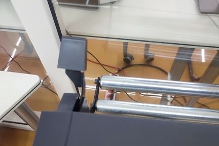
Take out your sticker by pushing back the handle.
-
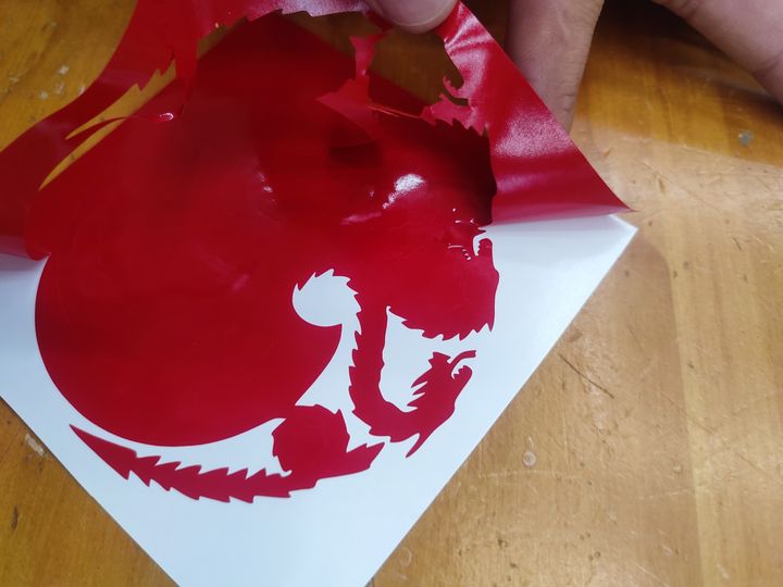
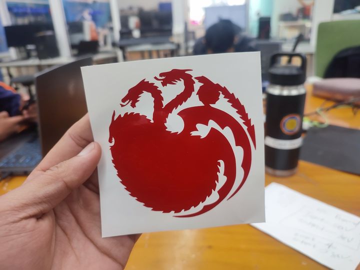
Start Weeding.
-
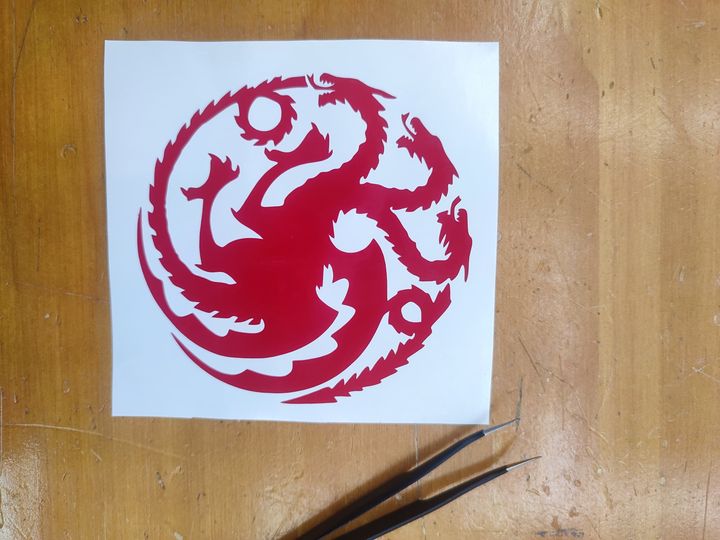
Weeding completed.
-
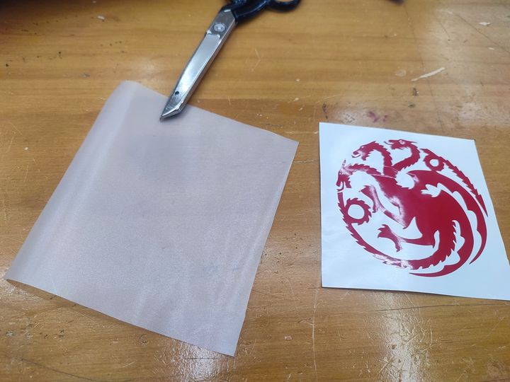
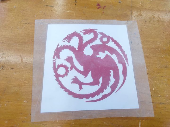
Paste the transfer tape on the front side of your sticker.
-
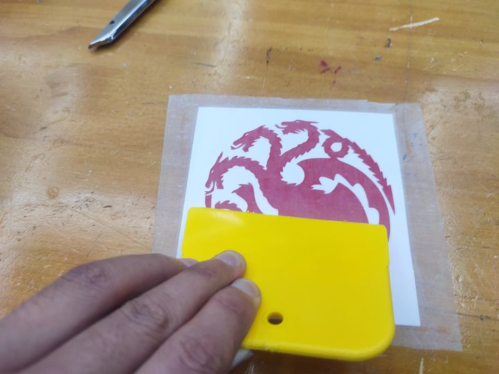
Use squeezer to properly paste the transfer tape on the sticker.

-
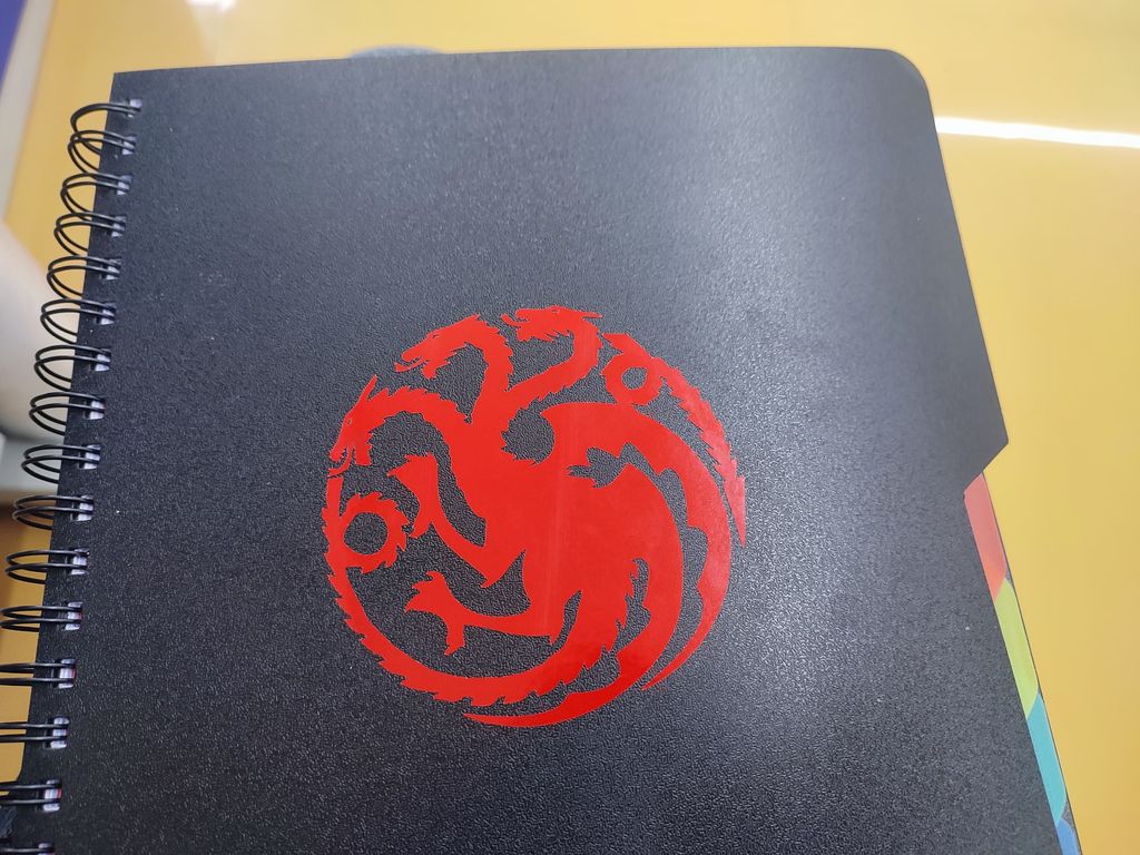
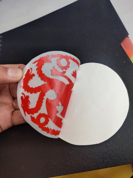
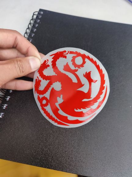
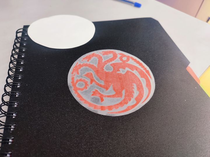
Paste it on the Book and squeeze it it properly.
-
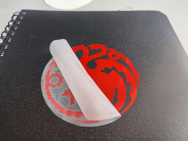
Remove the Transfer tape carefully.
-
Final Result.