9. Output Devices
This week's main objective is to add an output device to the microcontroller board created in the previous week. The device will be programmed to perform a specific function or task. The added devices are a servomotor and an oled display.
Research
This week's group assignment is to determine the consumption of one of the devices used. The results can be found here.
This week, I aimed to add an OLED display VMA438 to the printed circuit board created last week. The servo motor TD-8130MG of 360° was added during the previous task.
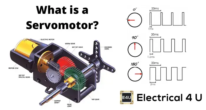
A servo motor is a motor that can precisely control angular position. It is commonly used in robotics, industrial automation, and scale models due to its adjustable accuracy, speed, torque, and compact size. However, it may be more expensive than other types of motors. Some common applications of this technology include vehicle steering systems, 3D printers, parabolic antennas, and solar tracking systems.
A servo motor, also known as a servo, is a device similar to a DC motor that can move to any position within its operating range and remain stable in that position. It achieves this through a built-in regulation system that can control both speed and position. The servo consists of a motor, an electronic control system, a potentiometer, and a set of gears.
The current required depends on the size of the servo. The manufacturer typically specifies the current consumption, which is mainly dependent on the torque. If the servo is interlocked, the current can exceed one ampere.
In the past, servo motors were limited to approximately 180° of rotation, but now there are servo motors that can be controlled for position and speed throughout 360°.

Images taken for https://www.electrical4u.com/what-is-servo-motor/
In this weekly assignment I used the board that was designed and built during week 8. In this week it is possible to see how I managed to control the rotation speed of the servomotor by means of a rotary encoder and the code I used is shown, along with a hero shot of the situation. For this reason I did not post it again on this page. You can go to the week 8 page to see it.
OLED (Organic Light Emitting Diode) displays are a display technology that uses organic compounds to emit light when an electric current is applied. Unlike LCD displays, which rely on a backlight, each pixel in an OLED display is self-emissive, meaning it can be turned on and off independently. This allows for deeper blacks and superior contrast, resulting in sharper, more realistic images. Another outstanding feature is their thin, flexible design, which allows for extremely lightweight displays. OLED displays also offer wide viewing angles, which means that image quality remains consistent when viewed from different positions.
The SSD1306 128x64 I2C OLED display modules are electronic devices that allow controlling each pixel individually and displaying both text and graphics via I2C communication, working with an operating voltage between 3.3V - 5.5V DC. They have 4 pins: Vcc, ground, SDL (or SDK) and SDA. The first two correspond to the power supply of the device, while the other two are used for communication via the I2C protocol (more information about this protocol can be found in my webpage of week 14). The individual control of the oled is done by the SSD1306 driver, which handles the protocol. More information about this driver can be found in its datasheet.
More information about this OLED display module can be found in its datasheet.
To exemplify the use of this device I made two programs, using the Adafruit_SSD1306.h library. The first one is a descending counter from ten to zero, centered on the screen. The code is shown below.
              #include <SPI.h>
              #include <Wire.h>
              #include <Adafruit_GFX.h>
              #include <Adafruit_SSD1306.h>

              Adafruit_SSD1306 display = Adafruit_SSD1306(128, 64, &Wire);

              void setup() {
                display.begin(SSD1306_SWITCHCAPVCC, 0x3C);
                display.clearDisplay();
                display.setTextColor(SSD1306_WHITE);

              }

              void loop() {
                display.clearDisplay();
                display.setTextSize(4);
                for(int i=10; i>=0; i--){
                  display.setCursor(40,15);
                  display.print(i);
                  display.display();
                  delay(1000);
                  display.clearDisplay();
                }

              }
The Adafruit_SSD1306.h library has dependencies on the Wire.h, SPI.h and Adafruit_GFX.h libraries, so they must be called. Subsequently, a display object is created which must have the dimensions of the screen we use (there are two types: 128x64 and 128x32 pixels). Then the screen is initialized with the correct address: 0x3C for 128x64 pixels screens and 0x3D for 128x32 pixels screens.
The clearDisplay() function clears the screen content and setTextColor() allows you to choose between black or white for the pixel colors, i.e. as an image and its negative.
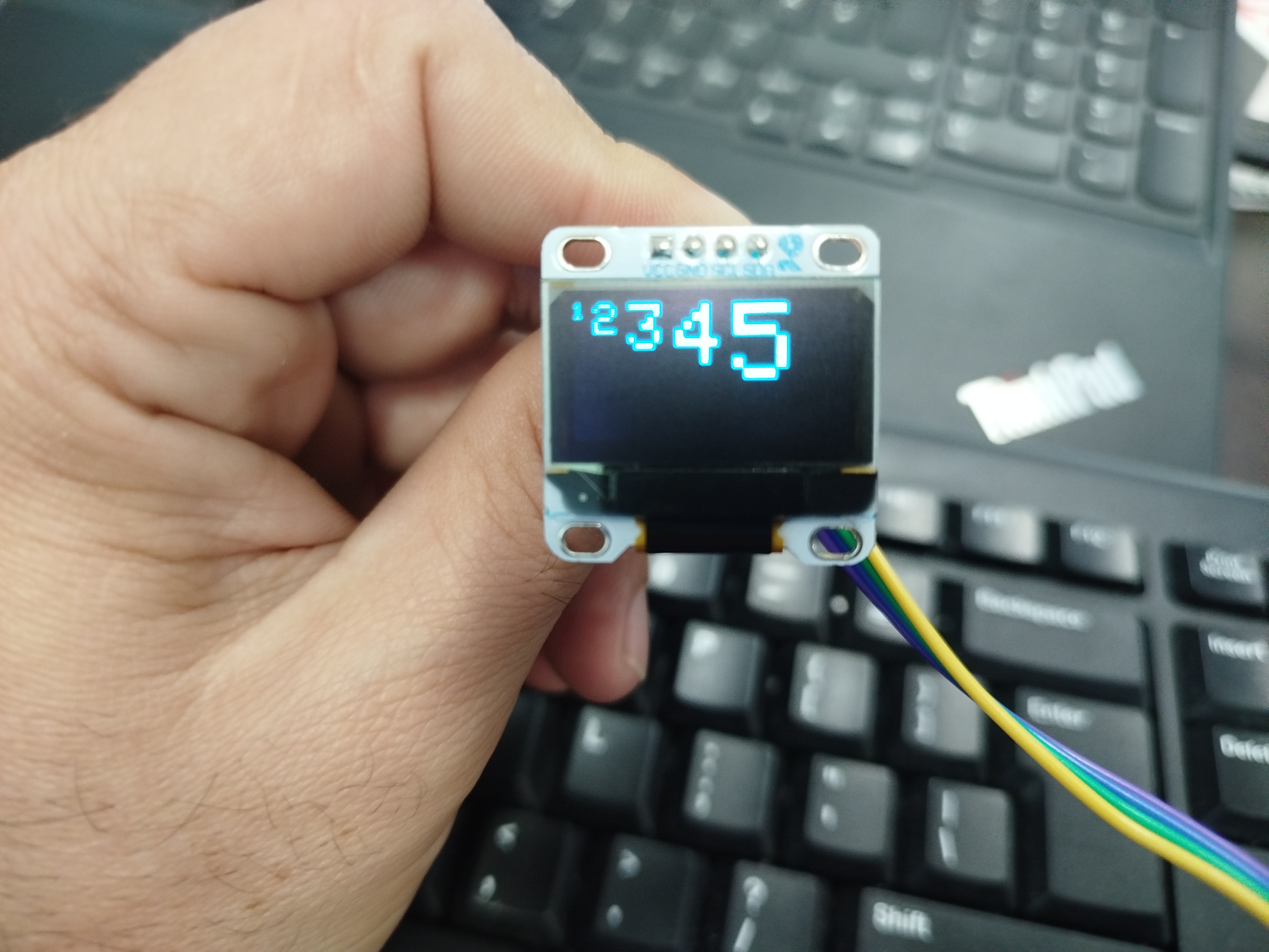
The setTextSize() function allows you to choose the size of the text to be placed on the screen and varies from 1 to 5, the setCursor() function varies the position of the text with the x (horizontal) and y (vertical) coordinates, as shown in the following image. To display the code on the screen, the function display.display() must be used.

The code to achieve what is shown in the image above is shown below:
              #include <SPI.h>
              #include <Wire.h>
              #include <Adafruit_GFX.h>
              #include <Adafruit_SSD1306.h>

              Adafruit_SSD1306 display = Adafruit_SSD1306(128, 64, &Wire);

              void setup() {
                display.begin(SSD1306_SWITCHCAPVCC, 0x3C);
                display.clearDisplay();
                display.setTextColor(SSD1306_WHITE);

              }

              void loop() {
                display.clearDisplay();
                display.setTextSize(1);
                display.setCursor(0,0);
                display.print("1");
                display.setTextSize(2);
                display.setCursor(10,0);
                display.print("2");
                display.setTextSize(3);
                display.setCursor(26,0);
                display.print("3");
                display.setTextSize(4);
                display.setCursor(48,0);
                display.print("4");
                display.setTextSize(5);
                display.setCursor(75,0);
                display.print("5");
                display.display();
                delay(1000);
                display.clearDisplay();
              }
The result of the descending counter is shown in the following video.
Descending counter.
For the second example I took the idea from a Youtube video. Here they convert an image into a bitmap and manage to display it on the OLED screen. The image I selected was the one I designed during week 16, a logo for my final project.

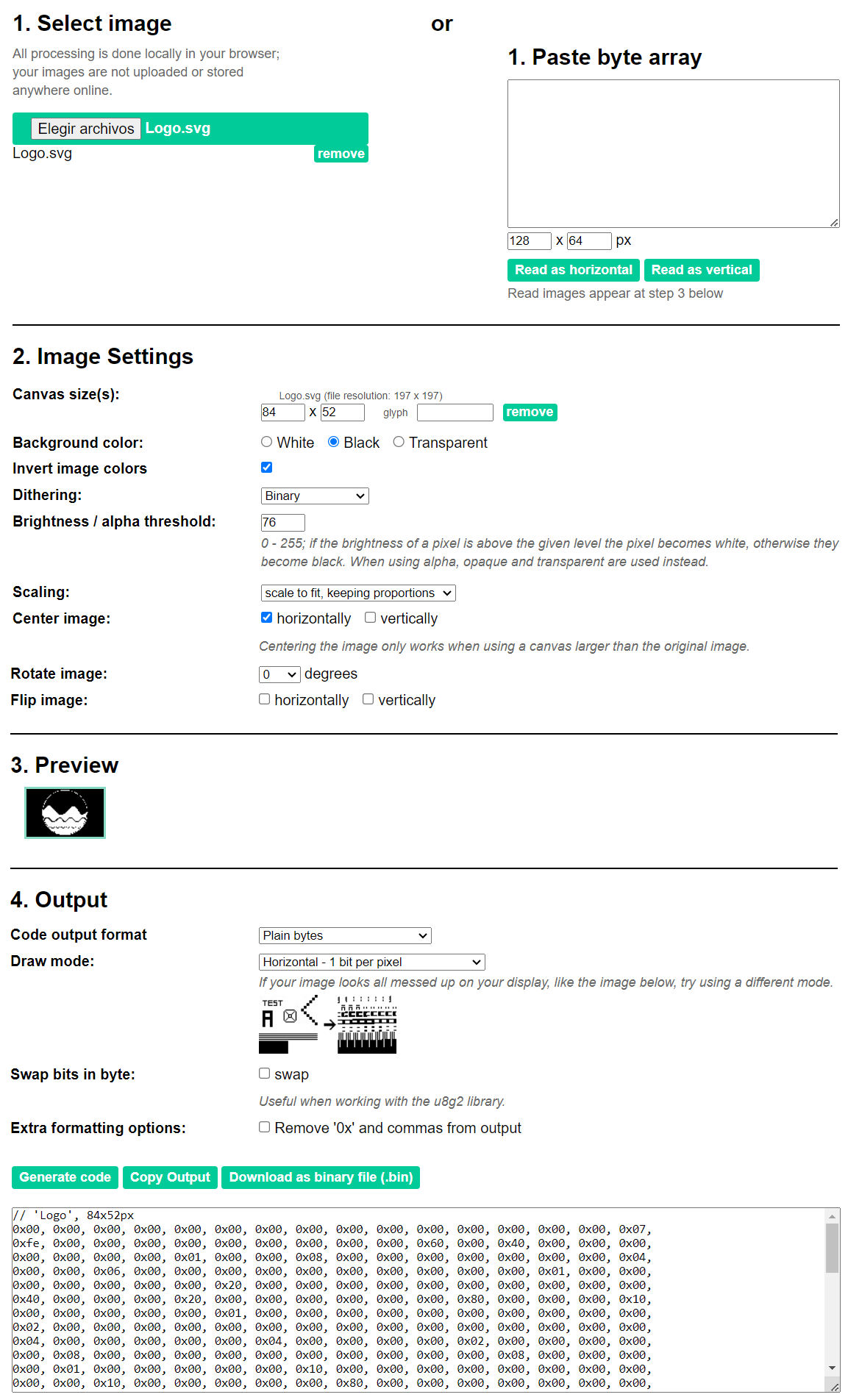
To convert the image to a bitmap I use the website https://javl.github.io/image2cpp/. The values indicated in the following image are recommended to obtain a clear image on the OLED screen.

The following code shows how to display the image and a text at the top of the display.
              #include <SPI.h>
              #include <Wire.h>
              #include <Adafruit_GFX.h>
              #include <Adafruit_SSD1306.h>

              #define DIR 0x3C

              Adafruit_SSD1306 display(128, 64, &Wire);

              #define LOGO_WIDTH 84
              #define LOGO_HEIGHT 52

              const unsigned char PROGMEM logo[] = {
              0x00, 0x00, 0x00, 0x00, 0x00, 0x00, 0x00, 0x00, 0x00, 0x00, 0x00, 0x00, 0x00, 0x00, 0x00, 0x07,
              0xfe, 0x00, 0x00, 0x00, 0x00, 0x00, 0x00, 0x00, 0x00, 0x00, 0x60, 0x00, 0x40, 0x00, 0x00, 0x00,
              0x00, 0x00, 0x00, 0x00, 0x01, 0x00, 0x00, 0x08, 0x00, 0x00, 0x00, 0x00, 0x00, 0x00, 0x00, 0x04,
              0x00, 0x00, 0x06, 0x00, 0x00, 0x00, 0x00, 0x00, 0x00, 0x00, 0x00, 0x00, 0x00, 0x01, 0x00, 0x00,
              0x00, 0x00, 0x00, 0x00, 0x00, 0x20, 0x00, 0x00, 0x00, 0x00, 0x00, 0x00, 0x00, 0x00, 0x00, 0x00,
              0x40, 0x00, 0x00, 0x00, 0x20, 0x00, 0x00, 0x00, 0x00, 0x00, 0x00, 0x80, 0x00, 0x00, 0x00, 0x10,
              0x00, 0x00, 0x00, 0x00, 0x00, 0x01, 0x00, 0x00, 0x00, 0x00, 0x00, 0x00, 0x00, 0x00, 0x00, 0x00,
              0x02, 0x00, 0x00, 0x00, 0x00, 0x00, 0x00, 0x00, 0x00, 0x00, 0x00, 0x00, 0x00, 0x00, 0x00, 0x00,
              0x04, 0x00, 0x00, 0x00, 0x00, 0x00, 0x04, 0x00, 0x00, 0x00, 0x00, 0x02, 0x00, 0x00, 0x00, 0x00,
              0x00, 0x08, 0x00, 0x00, 0x00, 0x00, 0x00, 0x00, 0x00, 0x00, 0x00, 0x00, 0x08, 0x00, 0x00, 0x00,
              0x00, 0x01, 0x00, 0x00, 0x00, 0x00, 0x00, 0x10, 0x00, 0x00, 0x00, 0x00, 0x00, 0x00, 0x00, 0x00,
              0x00, 0x00, 0x10, 0x00, 0x00, 0x00, 0x00, 0x00, 0x80, 0x00, 0x00, 0x00, 0x00, 0x00, 0x00, 0x00,
              0x00, 0x00, 0x00, 0x00, 0x00, 0x00, 0x00, 0x00, 0x21, 0xc0, 0x00, 0x00, 0x00, 0x00, 0x00, 0x00,
              0x00, 0x00, 0x00, 0x23, 0xe0, 0x00, 0x00, 0x78, 0x00, 0x40, 0x00, 0x00, 0x00, 0x00, 0x07, 0xf0,
              0x00, 0x00, 0xfc, 0x00, 0x40, 0x00, 0x00, 0x00, 0x00, 0x0f, 0xf8, 0x00, 0x01, 0xfe, 0x00, 0x00,
              0x00, 0x00, 0x00, 0x00, 0x5f, 0xfc, 0x00, 0x03, 0xff, 0x00, 0x00, 0x00, 0x00, 0x00, 0x00, 0x7f,
              0xfe, 0x00, 0x07, 0xff, 0x00, 0x00, 0x00, 0x00, 0x00, 0x00, 0x7f, 0xff, 0x00, 0x0f, 0xff, 0x80,
              0x00, 0x00, 0x00, 0x00, 0x00, 0x7f, 0xff, 0x80, 0x1f, 0xff, 0xc0, 0x60, 0x00, 0x00, 0x00, 0x00,
              0x7f, 0xff, 0xc0, 0x3f, 0xff, 0xc0, 0xc0, 0x00, 0x00, 0x00, 0x00, 0x7f, 0xff, 0xe0, 0xff, 0xff,
              0xe3, 0xc0, 0x00, 0x00, 0x00, 0x00, 0x7f, 0xff, 0xff, 0xff, 0xff, 0xff, 0x80, 0x00, 0x00, 0x00,
              0x00, 0x3f, 0xff, 0xff, 0xff, 0xff, 0xff, 0x80, 0x00, 0x00, 0x00, 0x00, 0x1f, 0xff, 0xff, 0xff,
              0xff, 0xff, 0x80, 0x00, 0x00, 0x00, 0x00, 0x10, 0x7f, 0xe3, 0xfc, 0x3f, 0xf0, 0xc0, 0x00, 0x00,
              0x00, 0x00, 0x27, 0x3f, 0x9d, 0xfb, 0xdf, 0xee, 0x40, 0x00, 0x00, 0x00, 0x00, 0x2f, 0x9f, 0x3e,
              0xf7, 0xef, 0xdf, 0x00, 0x00, 0x00, 0x00, 0x00, 0x0f, 0xce, 0x7e, 0x6f, 0xf7, 0xbf, 0x80, 0x00,
              0x00, 0x00, 0x00, 0x1f, 0xe1, 0xff, 0x1f, 0xf8, 0x7e, 0x80, 0x00, 0x00, 0x00, 0x00, 0x07, 0xff,
              0xff, 0xff, 0xff, 0xff, 0x00, 0x00, 0x00, 0x00, 0x00, 0x0f, 0xff, 0xff, 0xff, 0xff, 0xfd, 0x00,
              0x00, 0x00, 0x00, 0x00, 0x03, 0xff, 0xff, 0xff, 0xff, 0xfe, 0x00, 0x00, 0x00, 0x00, 0x00, 0x05,
              0xff, 0xff, 0xff, 0xff, 0xfc, 0x00, 0x00, 0x00, 0x00, 0x00, 0x03, 0xff, 0xff, 0xff, 0xff, 0xfc,
              0x00, 0x00, 0x00, 0x00, 0x00, 0x01, 0x5d, 0x69, 0xad, 0xbb, 0xd8, 0x00, 0x00, 0x00, 0x00, 0x00,
              0x00, 0xe3, 0x9e, 0x7b, 0xcf, 0x70, 0x00, 0x00, 0x00, 0x00, 0x00, 0x00, 0x7f, 0xff, 0xff, 0xff,
              0xa0, 0x00, 0x00, 0x00, 0x00, 0x00, 0x00, 0x3f, 0xff, 0xff, 0xff, 0xc0, 0x00, 0x00, 0x00, 0x00,
              0x00, 0x00, 0x1f, 0xff, 0xff, 0xff, 0x00, 0x00, 0x00, 0x00, 0x00, 0x00, 0x00, 0x05, 0xff, 0xff,
              0xfa, 0x00, 0x00, 0x00, 0x00, 0x00, 0x00, 0x00, 0x01, 0xff, 0xff, 0xe8, 0x00, 0x00, 0x00, 0x00,
              0x00, 0x00, 0x00, 0x00, 0xff, 0xff, 0x60, 0x00, 0x00, 0x00, 0x00, 0x00, 0x00, 0x00, 0x00, 0x0f,
              0xff, 0x00, 0x00, 0x00, 0x00, 0x00, 0x00, 0x00, 0x00, 0x00, 0x00, 0x00, 0x00, 0x00, 0x00, 0x00,
              0x00, 0x00, 0x00, 0x00, 0x00, 0x00, 0x00, 0x00, 0x00, 0x00, 0x00, 0x00
              };

              void setup() {
                Serial.begin(9600);
                if(!display.begin(SSD1306_SWITCHCAPVCC, DIR)) {
                  Serial.println(F("SSD1306 assignment failed"));
                }
                display.clearDisplay();
                display.setTextSize(1);
                display.setTextColor(WHITE);
                display.setCursor(20,0);
                display.println("Fab Lab ULB");
                display.display();
                display.drawBitmap( (display.width() - LOGO_WIDTH ) / 2,((display.height()- LOGO_HEIGHT) / 2 )+7, logo, LOGO_WIDTH, LOGO_HEIGHT, WHITE);
                display.display();
              }

              void loop() {
              }
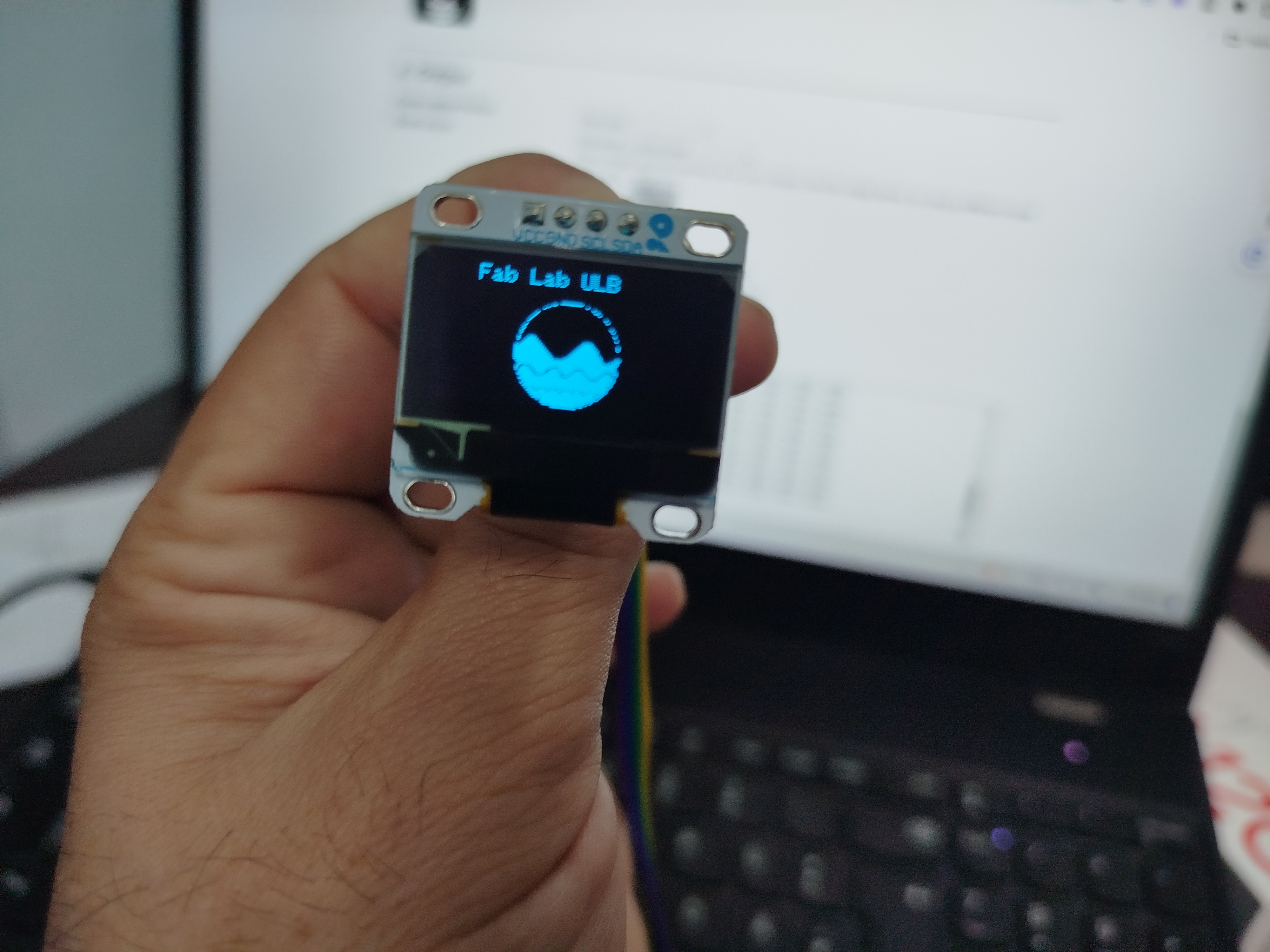
The final result of this example is shown below.

More information about the library Adafruit_SSD1306.h can be found here.