14. Networking and Communications
My main goal this week is to explain in detail how the communication protocols I used in previous weeks work, and to introduce a wireless communication protocol for this week's group assignment, which consisted of communicating two projects. The weekly group assignment can be found here.
I2C Protocol
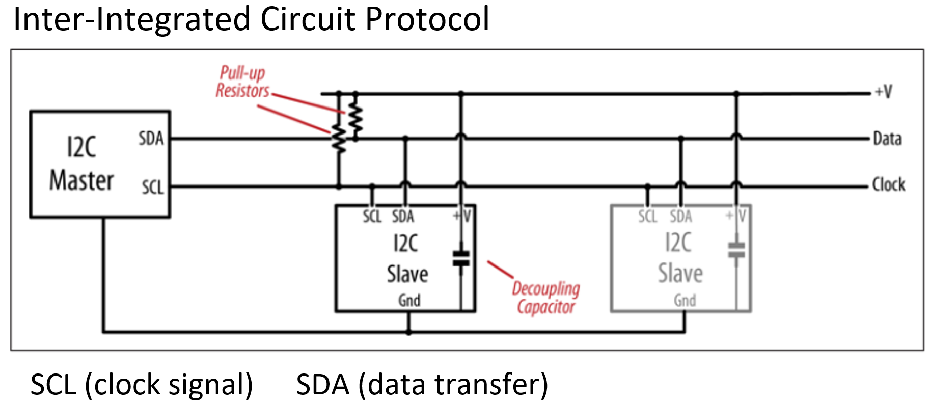
Schematization of I2C Protocol
Image taken from: Margolis, M., Jepson, B. & Weldin, N. R. (2020). Arduino Cookbook. Recipes to Begin, Expand, and Enhance Your Projects (3rd Ed.). O'Reilly Media
The I2C, I2C or IIC (Inter-Integrated Circuit) protocol is a serial bus protocol that allows bidirectional communication between multiple devices through the use of a single pair of data lines, consisting of one for clock (SCL) and one for data (SDA). Both lines require pull-up resistors to +V. The high level should be at least 0.7 x +V and the low level should be no more than 0.3 x +V. The I2C bus works with positive logic, i.e. a high level on the data line corresponds to a logic 1, a low level to a 0. I2C is distinguished by its straightforward implementation, minimal power consumption, and its capacity to regulate up to 128 devices on a unified network.
Data in the I2C protocol is sent as a message. These messages are broken down into parts called frames. Each message has an address frame that points to the address of the slave device, and then come one or more data frames that carry the information we want to transmit. Also included are start and stop signals, bits that indicate whether we are reading or writing, and bits that confirm whether everything went well (ACK) or if there was a problem (NACK) between the data frames. The start condition occurs when the SDA line goes from high to low before the SCL line goes from high to low. The stop condition occurs when the SDA line goes up from a low level to a high level after the SCL line goes from low to high. The address frame is a unique sequence of 7 or 10 bits that identifies each slave device when the master wants to communicate with it. The read/write bit is a bit that tells whether the master is sending data to the slave (low level) or requesting data from it (high level). Finally, after each frame of a message, an acknowledgement or non-acknowledgement bit is sent; if the receiving device successfully receives an address or data frame, it responds with an ACK bit to the sender.
The I2C protocol does not have slave select lines like SPI, so it needs another way to inform the slave that data is being sent to it and not to another slave. This is done by addressing. The address frame is always the first frame after the start bit in a new message. The master sends the address of the slave it wants to communicate with to all slaves connected to it. Each slave then compares the address sent by the master with its own address. If the address matches, the slave sends a low voltage ACK bit to the master. If the address does not match, the slave does nothing and the SDA line remains high. The address frame includes a single bit at the end that informs the slave whether the master wants to write data to it or receive data from it. If the master wants to send data to the slave, the read/write bit is a voltage level low. If the master is requesting data from the slave, the bit is a high voltage level. Once the master detects the ACK bit from the slave, the first data frame is ready to be sent. The data frame is always 8 bits long and is sent with the most significant bit first. Each data frame is immediately followed by an ACK/NACK bit to verify that the frame has been received correctly. The ACK bit must be received by either the master or the slave (depending on who is sending the data) before the next data frame can be sent. Once all data frames have been sent, the master can send a stop condition to the slave to stop transmission. The stop condition is a low-to-high voltage transition on the SDA line after a low-to-high transition on the SCL line, with the SCL line remaining high.
I2C protocol steps:
- The master transmits the start condition to each connected slave by alternately raising and lowering the voltage on the SDA line, followed by a similar alternation on the SCL line.
- The master transmits the 7-bit or 10-bit address of the desired slave to be communicated with, along with the read/write bit, to each slave.
- Each slave is programmed to perform a comparison between the address transmitted by the master and its own unique address. In the event of a matching address, the slave responds with an ACK bit by pulling the SDA line low for one bit. In the event that the address transmitted by the master does not correspond to that of the slave, the latter maintains the SDA line in a high state.
- The master then transmits or receives the data frame.
- Once a data frame has been successfully transferred, the receiving device responds with an ACK bit, thereby indicating to the sender that the frame has been received.
- In order to terminate the data transmission, the master device transmits a stop condition to the slave device by raising the SCL line to a high level before raising the SDA line to a high level.
On week 9 I used a SSD1306 128x64 I2C OLED display modules, which use I2C protocol to communicate with the microcontroller and display the indications. Specifically, for the second example I did I took the idea from a Youtube video, converting an image into a bitmap and manage to display it on the OLED screen. The image I selected was the one I designed during week 16, a logo for my final project.
On this week I decodified the I2C protocol using a digital oscilloscope. The main idea is very simple if you know how the protocol works. I used the two channels of my oscilloscope, a Rigol DS1052D, one for a SCL signal and the other for the SDA signal.
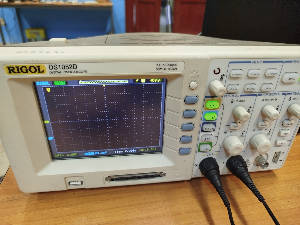
Oscilloscope Rigol used for the decodifing of I2C protocol.
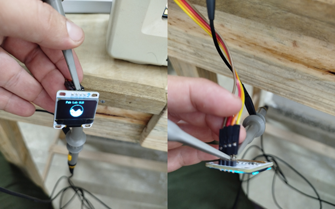
Connecting the oscilloscope to the OLED display.
The channel 1 was connected to clock signal (SDL) and the channel 2 to the data signal (SDA). According the way of implementation of this protocol, the clock signal is a pulse train and the data signal contain the information, as was described before. The last bit (0 on both cases) show that the message was received correctly (ACK). The bit before the last one (0 on both cases) show that the message was reading for the peripherial. The other bits represent the information received for the peripherial and sent for the controller. So, the protocol works correctly.
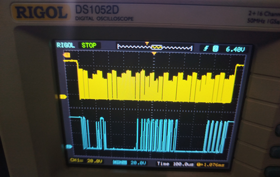
Decodifing of I2C protocol.
Others communication protocols
Another widely used protocol is SPI (Serial Peripheral Interface), which allows synchronous serial communication between microcontrollers and peripherals. Unlike I2C, SPI uses a 4-line bus: one for clock (SCLK), one for sending data (MOSI), one for receiving data (MISO) and one for device selection (or Slave Selection SS). SPI stands out for its higher data transfer rate and ease of implementation, making it a popular choice for applications requiring higher performance.
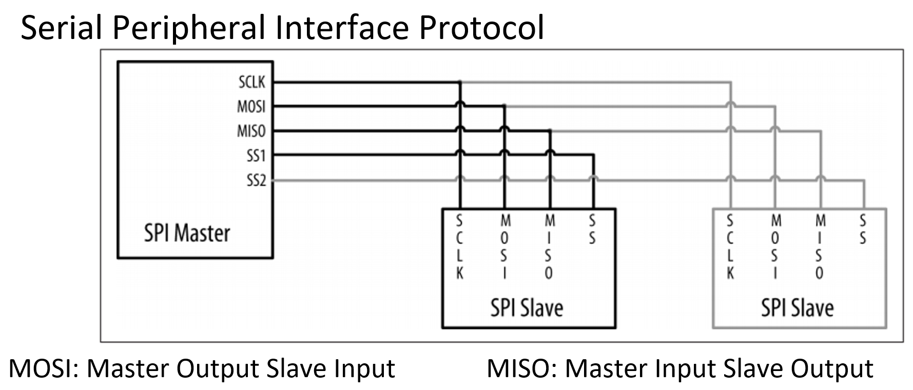
Schematization of SPI Protocol
Image taken from: Margolis, M., Jepson, B. & Weldin, N. R. (2020). Arduino Cookbook. Recipes to Begin, Expand, and Enhance Your Projects (3rd Ed.). O'Reilly Media
In contrast, the UART (Universal Asynchronous Receiver-Transmitter) protocol is an asynchronous serial communication standard that is widely used in data transmission between devices. Unlike I2C and SPI, UART employs only two signal lines: one for transmitting (TX) and one for receiving (RX) data. In the context of UART communication, the transmission of data is accomplished through the use of frames, each of which is comprised of a start bit, data bits, and a parity bit (if present). The start bit, which is represented by a logic low signal (0), serves to indicate the beginning of the frame. The data bits, which typically consist of 8 bits, are transmitted from the least significant bit to the most significant bit. Finally, the parity bit (if present) is used to detect errors during transmission. The parity bit can be either even or odd, indicating that the total number of bits in a given frame is even or odd, respectively. The stop bit is a high logic signal (1) indicating the end of the frame. Its length can be 1 or 2 bits. The use of the parity bit and the length of the stop bit depend on the specific configuration of the UART protocol used. UART is distinguished by its simplicity, low transfer rate, and wide compatibility, rendering it an appropriate choice for straightforward communication applications, such as connecting devices via serial ports.
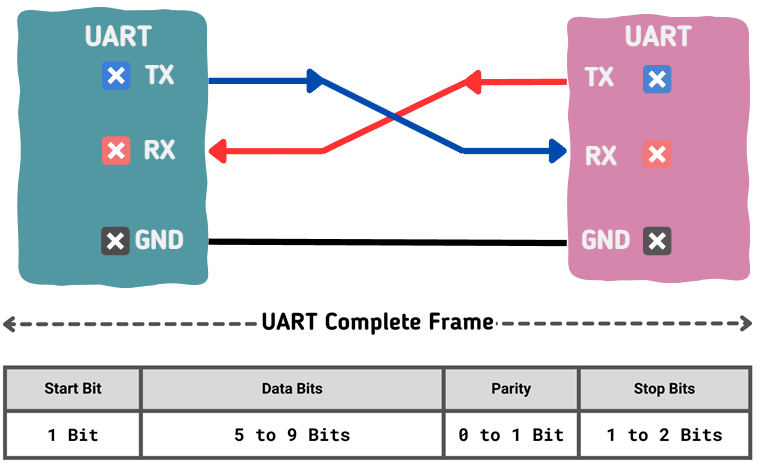
Schematization of UART Protocol
Image taken from: https://embeddedwala.com/Blogs/DigitalCommunication/Getting-Started-with-UART:-A-Beginners-Guide
In the field of wireless communications, WiFi and Bluetooth are two of the most prominent protocols. The WiFi protocol, based on the IEEE 802.11 standard, enables the connection of devices to a wireless local area network (WLAN) via high-frequency radio waves. This technology is characterized by its high data transfer speed and its ability to support multiple users simultaneously, making it a popular choice for applications that require a high-speed network connection, such as video streaming or Internet access.
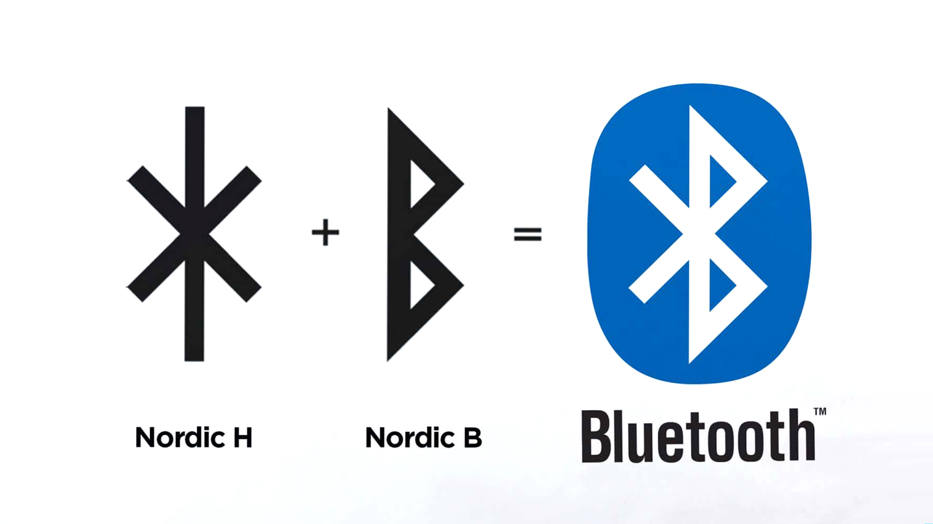
For antoher way, Bluetooth is a wireless communication technology that enables electronic devices to connect over short distances. It was initially developed in 1994 by a consortium of companies led by Ericsson. Bluetooth is used to transfer files, music, voice, and data between compatible devices such as cell phones, computers, headsets, and speakers. It is characterized by low power consumption, low cost, and wide compatibility between different brands and models. Bluetooth has become an industry standard for wireless device connectivity, being widely adopted in a variety of personal and consumer applications. Bluetooth employs short-range radio waves to establish a wireless connection between devices. When two Bluetooth devices meet, they exchange information to authenticate each other and establish a secure link. Once connected, they can transmit data at rates of up to 24 Mbps, depending on the version. Bluetooth employs a frequency hopping system to circumvent interference, oscillating at a rate of approximately 1600 times per second. This enables a dependable connection even in environments with a considerable amount of electromagnetic noise. The system achieves low power consumption by cycling on and off, allowing devices to enter a low-power mode when not transmitting.
Communication technologies and protocols, both wired and wireless, play a pivotal role in the interconnection of electronic devices, enabling data exchange and remote control in an efficient and versatile manner. Each protocol possesses its own distinctive characteristics and advantages, rendering it suitable for a diverse range of applications and communication requirements.
Bluetooth Low Energy (BLE)
Bluetooth Low Energy (BLE) is a wireless personal area network (WPAN) technology designed and marketed by the Bluetooth Special Interest Group (SIG) for applications in the healthcare, fitness, and beacon industries, as well as the security and home entertainment sectors. BLE differs from the original Bluetooth technology in that it is specifically designed to provide low power consumption while simultaneously maintaining a similar communication range. It is also the inaugural open wireless communication technology, offering communication between mobile devices, computers, and other smaller devices, including button cell devices. BLE chips are designed to operate on low power, facilitating communication between smaller devices, such as button cells, and Bluetooth devices, which operate at 2.4 GHz (within one of the ISM bands) with a transfer rate of 1 Mbps at the physical layer. These chips have a wide range of potential applications within the industry, in addition to their similar size to traditional Bluetooth devices. Furthermore, they are equipped with security measures, such as AES encryption and configurable security schemes.
In contrast to the standard Bluetooth communication, which is based on an asynchronous serial connection (UART), a BLE radio functions as a community bulletin board. The computers that connect to it are analogous to community members reading the bulletin board. Each radio assumes the role of either a bulletin board or a reader. If a radio is designated as a bulletin board (referred to as a peripheral device in BLE terminology), it posts data for all radios in the community to read. If your radio is a reader (referred to as a central device in BLE terms), it reads information from any of the bulletin boards (referred to as peripheral devices) that contain the data that you wish to access and process. It can be considered that the peripheral devices serve as a repository of information for the reader radios, analogous to a server in a client-server transaction. Similarly, the central devices are the clients of the Bluetooth® LE world because they access the information available from the peripherals, thus providing the functionality to interact with the BLE network.
A BLE edge device may be conceptualized as a bulletin board, with the central devices functioning as viewers of the board. The central devices observe the services, obtain the data, and then move on. Each transaction is rapid (on the order of a few milliseconds), allowing multiple central devices to concurrently retrieve data from a peripheral.
The information presented by a peripheral is structured into services, each of which is subdivided into features. The services may be considered the notices on a bulletin board, while the features represent the individual paragraphs of those notices. If one is a peripheral device, one simply updates each service feature as needed, without concern for whether or not the central devices read them. Conversely, if one is a central device, one connects to the peripheral and then reads the boxes one desires. If a given feature is both readable and writable, then both the peripheral and the central device are capable of modifying it.
The central devices serve as clients, reading and writing information from the peripheral devices. The latter are designated as servers and are responsible for providing sensor data in a readable format and offering read/write capabilities for controlling actuators such as motors, lights, and so on.
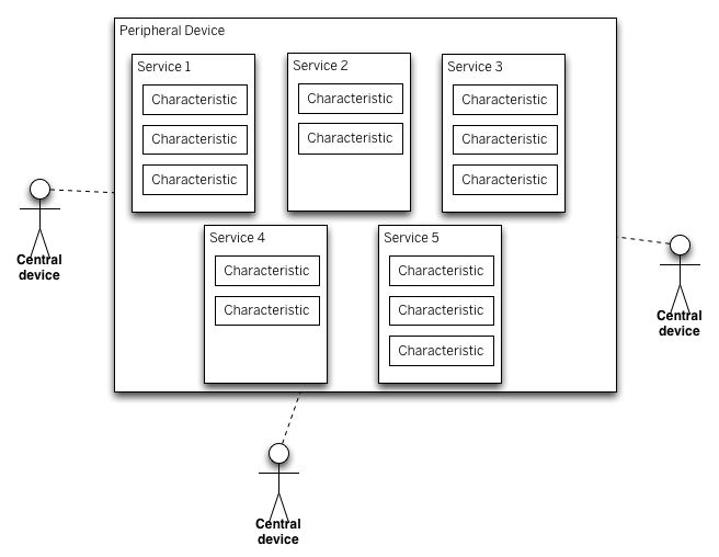
BLE Bulletin Board Model
Image taken from: https://www.arduino.cc/reference/en/libraries/arduinoble/
A BLE peripheral will provide services, which in turn will provide features. The user has the option of defining their own services or utilising standard services (see section 3.4). Services are identified by unique numbers, known as UUIDs. It is important to be aware of the UUIDs of other contexts. Standard services have a 16-bit UUID, while custom services have a 128-bit UUID. The ability to define services and features depends on the radio in use and its firmware.
Central Device code
  #include "ArduinoBLE.h2"
  #include "Arduino_APDS9960.h"

  const char* deviceServiceUuid = "19b10000-e8f2-537e-4f6c-d104768a1214";
  const char* deviceServiceCharacteristicUuid = "19b10001-e8f2-537e-4f6c-d104768a1214";

  int gesture = -1;
  int oldGestureValue = -1;

  void setup() {
    Serial.begin(9600);
    while (!Serial);

    if (!APDS.begin()) {
      Serial.println("* Error initializing APDS9960 sensor!");
    }

    APDS.setGestureSensitivity(80);

    if (!BLE.begin()) {
      Serial.println("* Starting Bluetooth® Low Energy module failed!");
      while (1);
    }

    BLE.setLocalName("Nano 33 BLE (Central)");
    BLE.advertise();

    Serial.println("Arduino Nano 33 BLE Sense (Central Device)");
    Serial.println(" ");
  }

  void loop() {
    connectToPeripheral();
  }

  void connectToPeripheral(){
    BLEDevice peripheral;

    Serial.println("- Discovering peripheral device...");

    do
    {
      BLE.scanForUuid(deviceServiceUuid);
      peripheral = BLE.available();
    } while (!peripheral);

    if (peripheral) {
      Serial.println("* Peripheral device found!");
      Serial.print("* Device MAC address: ");
      Serial.println(peripheral.address());
      Serial.print("* Device name: ");
      Serial.println(peripheral.localName());
      Serial.print("* Advertised service UUID: ");
      Serial.println(peripheral.advertisedServiceUuid());
      Serial.println(" ");
      BLE.stopScan();
      controlPeripheral(peripheral);
    }
  }

  void controlPeripheral(BLEDevice peripheral) {
    Serial.println("- Connecting to peripheral device...");

    if (peripheral.connect()) {
      Serial.println("* Connected to peripheral device!");
      Serial.println(" ");
    } else {
      Serial.println("* Connection to peripheral device failed!");
      Serial.println(" ");
      return;
    }

    Serial.println("- Discovering peripheral device attributes...");
    if (peripheral.discoverAttributes()) {
      Serial.println("* Peripheral device attributes discovered!");
      Serial.println(" ");
    } else {
      Serial.println("* Peripheral device attributes discovery failed!");
      Serial.println(" ");
      peripheral.disconnect();
      return;
    }

    BLECharacteristic gestureCharacteristic = peripheral.characteristic(deviceServiceCharacteristicUuid);

    if (!gestureCharacteristic) {
      Serial.println("* Peripheral device does not have gesture_type characteristic!");
      peripheral.disconnect();
      return;
    } else if (!gestureCharacteristic.canWrite()) {
      Serial.println("* Peripheral does not have a writable gesture_type characteristic!");
      peripheral.disconnect();
      return;
    }

    while (peripheral.connected()) {
      gesture = gestureDetectection();

      if (oldGestureValue != gesture) {
        oldGestureValue = gesture;
        Serial.print("* Writing value to gesture_type characteristic: ");
        Serial.println(gesture);
        gestureCharacteristic.writeValue((byte)gesture);
        Serial.println("* Writing value to gesture_type characteristic done!");
        Serial.println(" ");
      }

    }
    Serial.println("- Peripheral device disconnected!");
  }

  int gestureDetectection() {
    if (APDS.gestureAvailable()) {
      gesture = APDS.readGesture();

      switch (gesture) {
        case GESTURE_UP:
          Serial.println("- UP gesture detected");
          break;
        case GESTURE_DOWN:
          Serial.println("- DOWN gesture detected");
          break;
        case GESTURE_LEFT:
          Serial.println("- LEFT gesture detected");
          break;
        case GESTURE_RIGHT:
          Serial.println("- RIGHT gesture detected");
          break;
        default:
          Serial.println("- No gesture detected");
          break;
        }
      }
      return gesture;
  }
Periperial Device code
#include "ArduinoBLE.h"

enum {
  GESTURE_NONE  = -1,
  GESTURE_UP    = 0,
  GESTURE_DOWN  = 1,
  GESTURE_LEFT  = 2,
  GESTURE_RIGHT = 3
};

const char* deviceServiceUuid = "19b10000-e8f2-537e-4f6c-d104768a1214";
const char* deviceServiceCharacteristicUuid = "19b10001-e8f2-537e-4f6c-d104768a1214";

int gesture = -1;

BLEService gestureService(deviceServiceUuid);
BLEByteCharacteristic gestureCharacteristic(deviceServiceCharacteristicUuid, BLERead | BLEWrite);


void setup() {
  Serial.begin(9600);
  while (!Serial);

  pinMode(LEDR, OUTPUT);
  pinMode(LEDG, OUTPUT);
  pinMode(LEDB, OUTPUT);
  pinMode(LED_BUILTIN, OUTPUT);

  digitalWrite(LEDR, HIGH);
  digitalWrite(LEDG, HIGH);
  digitalWrite(LEDB, HIGH);
  digitalWrite(LED_BUILTIN, LOW);


  if (!BLE.begin()) {
    Serial.println("- Starting Bluetooth® Low Energy module failed!");
    while (1);
  }

  BLE.setLocalName("Arduino Nano 33 BLE (Peripheral)");
  BLE.setAdvertisedService(gestureService);
  gestureService.addCharacteristic(gestureCharacteristic);
  BLE.addService(gestureService);
  gestureCharacteristic.writeValue(-1);
  BLE.advertise();

  Serial.println("Nano 33 BLE (Peripheral Device)");
  Serial.println(" ");
}

void loop() {
  BLEDevice central = BLE.central();
  Serial.println("- Discovering central device...");
  delay(500);

  if (central) {
    Serial.println("* Connected to central device!");
    Serial.print("* Device MAC address: ");
    Serial.println(central.address());
    Serial.println(" ");

    while (central.connected()) {
      if (gestureCharacteristic.written()) {
         gesture = gestureCharacteristic.value();
         writeGesture(gesture);
       }
    }

    Serial.println("* Disconnected to central device!");
  }
}

void writeGesture(int gesture) {
  Serial.println("- Characteristic  has changed!");

   switch (gesture) {
      case GESTURE_UP:
        Serial.println("* Actual value: UP (red LED on)");
        Serial.println(" ");
        digitalWrite(LEDR, LOW);
        digitalWrite(LEDG, HIGH);
        digitalWrite(LEDB, HIGH);
        digitalWrite(LED_BUILTIN, LOW);
        break;
      case GESTURE_DOWN:
        Serial.println("* Actual value: DOWN (green LED on)");
        Serial.println(" ");
        digitalWrite(LEDR, HIGH);
        digitalWrite(LEDG, LOW);
        digitalWrite(LEDB, HIGH);
        digitalWrite(LED_BUILTIN, LOW);
        break;
      case GESTURE_LEFT:
        Serial.println("* Actual value: LEFT (blue LED on)");
        Serial.println(" ");
        digitalWrite(LEDR, HIGH);
        digitalWrite(LEDG, HIGH);
        digitalWrite(LEDB, LOW);
        digitalWrite(LED_BUILTIN, LOW);
        break;
      case GESTURE_RIGHT:
        Serial.println("* Actual value: RIGHT (built-in LED on)");
        Serial.println(" ");
        digitalWrite(LEDR, HIGH);
        digitalWrite(LEDG, HIGH);
        digitalWrite(LEDB, HIGH);
        digitalWrite(LED_BUILTIN, HIGH);
        break;
      default:
        digitalWrite(LEDR, HIGH);
        digitalWrite(LEDG, HIGH);
        digitalWrite(LEDB, HIGH);
        digitalWrite(LED_BUILTIN, LOW);
        break;
    }
}
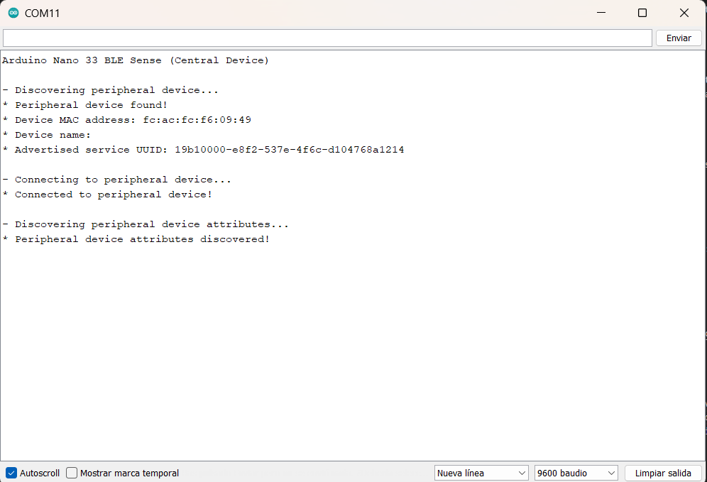
Established connection displayed through Serial Monitor.

