Week 5
3D Scanning and Printing
Group Assignment
- Test the design rules for your 3D printer(s)
Design rules for 3D printing
Prusa i3 MK3S+
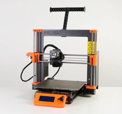
FDM printer, PLA material, 0.4mm nozzle, print area: 250 x 210 x 210 mm
Print settings: 0.20mm quality, no supports, 20% infill
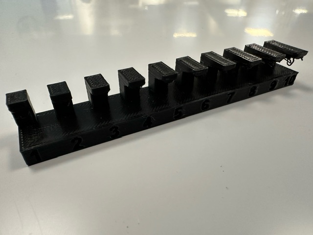
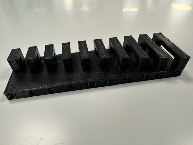
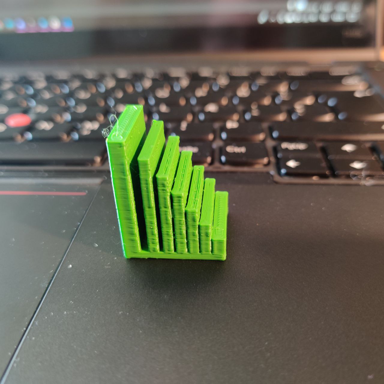
Angle test
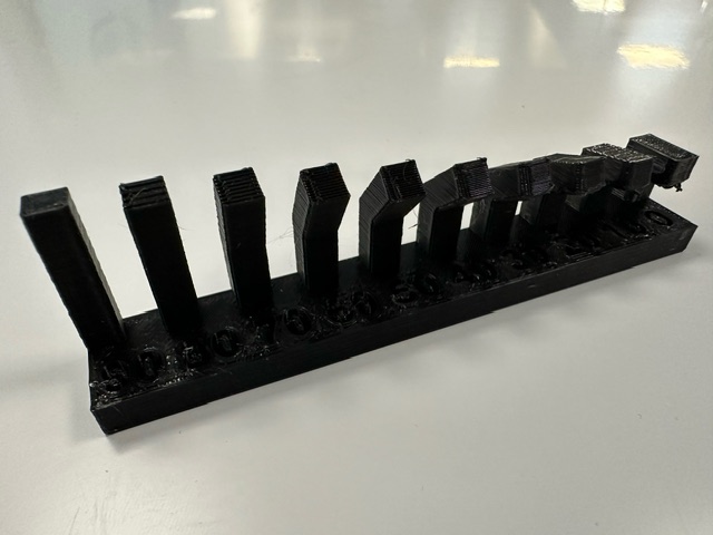
This 3D print serves as a crucial experiment to determine the safe printing angles for maintaining quality in 3D printed objects. It features nine pillars, each printed at increasing angles from 0 degrees to 90 degrees. Observations indicate that print quality remains acceptable up to a 50-degree angle. Beyond this threshold, the quality noticeably diminishes, highlighting the critical impact of print angle on the outcome's fidelity. This experiment underscores the importance of angle consideration in 3D printing processes to ensure optimal results. The model is available on the Fab Academy class site. Download .stl file
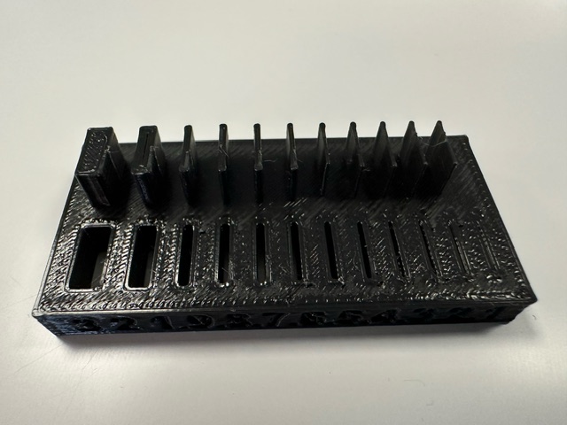
Overhang test
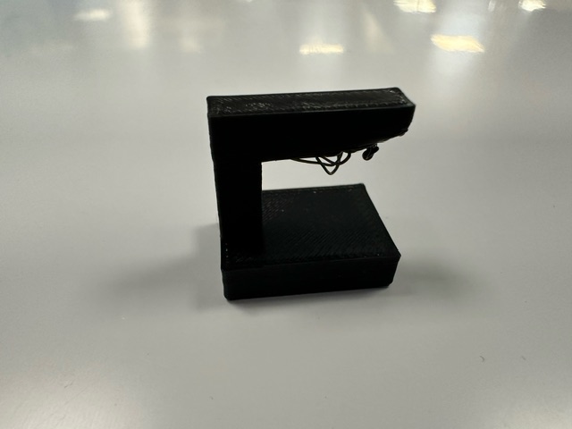
This overhang test comprises two distinct files designed to illustrate the critical role of supports in 3D printing, especially when dealing with overhangs at challenging angles. The first file features a singular overhang extending 15mm at a 90-degree angle, demonstrating that without adequate supports, the print quality is significantly compromised, rendering the outcome unacceptable. The second file methodically explores overhangs through ten pillars, each with a 90-degree overhang that increases incrementally from 1mm to 10mm in length. Observations reveal a discernible decline in print quality beginning at just 2mm, underscoring the necessity of supports or design adjustments to mitigate extreme overhangs. Together, these tests highlight the imperative of incorporating supports or avoiding 90-degree overhangs in model designs to ensure the integrity and quality of 3D printed objects. The model is available on the Fab Academy class site. Download .stl file 1 Download .stl file 2
Bridging
This bridging test is meticulously designed to evaluate the performance of 3D printing across varying lengths of unsupported spans, featuring a series of ten bridges. The initial bridge spans a modest 2mm, with each subsequent bridge extending an additional 2mm in length, culminating in a 20mm bridge. The results of this test are remarkably positive, indicating that up to a certain point, 3D printing can effectively manage bridging without direct support. All bridges, from the shortest to those approaching the 20mm mark, display acceptable quality, demonstrating the capability of 3D printing technology to create stable, unsupported structures. However, the longest bridge, at 20mm, exhibits slight sagging, a minor deviation from the otherwise consistent quality observed in shorter spans. This subtle sagging at the extreme end of the test spectrum highlights the physical limitations of material cooling and gravity's effect on 3D printed structures, underscoring the importance of considering bridge length in design and the potential need for supports or adjustments for longer spans. The model is available on the Fab Academy class site. Download .stl file
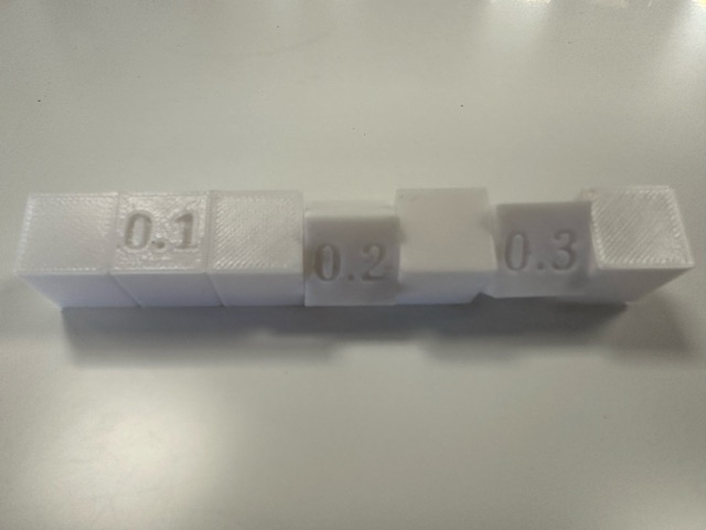
Wall thickness
The wall thickness and gap tests are essential evaluations to determine the precision capabilities of 3D printing technology, particularly in achieving fine details and maintaining structural integrity at minimal dimensions. These tests explore a range of gaps and wall thicknesses, starting from a mere 0.1mm and incrementally increasing up to 1mm, with additional tests for 2mm and 3mm gaps. The findings from the gap test reveal that gaps beginning at 0.2mm are deemed acceptable, with the 0.1mm gap being distinguishable yet falling short of acceptable quality, indicating the printer's limitations in resolving extremely narrow spaces.
On the counterpart, the wall thickness test uncovers a similar boundary of the printer's capabilities. All tested wall thicknesses, mirroring the gap sizes from 0.2mm onwards, are successfully printed and meet acceptable standards, showcasing the printer's adeptness at creating slender yet stable structures. However, the printer did not attempt to print the 0.1 mm wall since the slicer software deemed it too fine to print. This outcome highlights a critical threshold in the printer's precision, underscoring the challenge of producing ultra-thin walls and the necessity of adjusting design parameters to align with the printer's capabilities. Together, these tests offer valuable insights into optimizing designs for 3D printing by acknowledging the practical limits of gap resolution and wall thickness that can be reliably achieved. The model is available on the Fab Academy class site. Download .stl file
Movement test
The movement test model is designed to assess the 3D printer's ability to create parts with functional tolerances directly from the print bed, specifically focusing on the precision required for in-place movement. It consists of seven cubes, each measuring 15mm on all sides. These cubes are arranged in a linear sequence and are interconnected in a specific pattern to test the minimal gap tolerances that allow for free movement without fusing parts together.
Cubes 1, 3, 5, and 7 serve as anchor points and are directly connected by 5mm diameter cylinders, acting as axles or hinges around which the intermediate cubes (2, 4, and 6) are expected to rotate or move. Cube 2 is positioned between cubes 1 and 3 and has a 0.1mm gap from each, allowing for a theoretical space for movement. It also features a 5.2mm hole through which the connecting cylinder passes. However, this configuration results in the cube fusing to its neighboring cubes, suggesting that a 0.1mm tolerance is insufficient for creating separate, movable parts in this context. Cube 4, situated between cubes 3 and 5, incorporates a slightly larger gap of 0.2mm from its adjacent cubes and a 5.4mm hole for the cylinder. This setup successfully allows cube 4 to rotate or move around the cylinder, indicating that a tolerance of 0.2mm is adequate for print-in-place movement without the parts sticking together. Cube 6, placed between cubes 5 and 7, follows the increasing tolerance trend with a 0.3mm gap from its neighbors and a 5.6mm hole for the cylinder. This cube also demonstrates the ability to move freely, further confirming that a tolerance of at least 0.2mm is necessary for effective print-in-place functionality. This model effectively tests the minimum tolerance required to achieve movable parts directly off the print bed, highlighting the critical balance between too tight tolerances, which lead to fused parts, and sufficient spacing, which allows for functional movement. Model created by Andri Sæmundsson Download .stl file
FLSUN v400
FDM printer, PLA material, 0.4mm nozzle, print area: 300 x 300 x 410 mm
Print settings: 0.20mm quality, no supports, 20% infill
Spacing tolerance
A spacing tolerance test was conducted with the FLSUN V400 3D printer, various gaps between vertical columns were examined, starting from a minimal gap of 0.2mm and extending to wider gaps of 0.3mm, 0.4mm, 0.5mm, 1mm, and finally 2mm. The objective was to ascertain the smallest gap that could be reliably printed without the columns fusing together or losing definition. The test results demonstrated that a 0.2mm gap was too narrow to achieve satisfactory separation between columns, leading to unacceptable merging or insufficient clarity. In contrast, gaps of 0.3mm and larger were found to be effective, with the printer accurately maintaining these spacings, thereby ensuring clear and distinct columns. Model created by Róbert H. Pálsson Download .stl file