13. Embedded Networking and Communications
First of all, in our group webpage (click here), You will find relevant information on the topic taught by experts.
Network and Communication refer to the interconnected systems and devices that enable the transfer of data and information between various endpoints. The main components of a network and communication system include hardware devices such as computers, routers, switches, and modems, and software protocols that govern the flow of data between these devices.
A communications protocol is a set of formal rules describing how to transmit or exchange data, especially across a network. In this assignment we are going to see three common serial communication protocols in embedded and electronic systems in general. Each has its own characteristics, advantages and disadvantages.
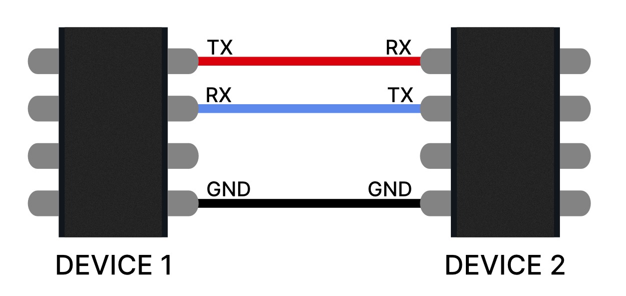
UART (Universal Asynchronous Receiver/Transmitter)
UART is an asynchronous serial communication protocol that transmits data serially bit by bit without a shared clock between the transmitter and receiver. It uses transmit (TX) and receive (RX) lines to send and receive data between devices.
Advantages:
- Easy to implement and understand.
- Does not require a synchronized clock between connected devices.
- Good choice for short-distance communications.
Disadvantages:
- More susceptible to synchronization errors and noise compared to synchronous protocols.
- Not as bandwidth-efficient as SPI and I2C.
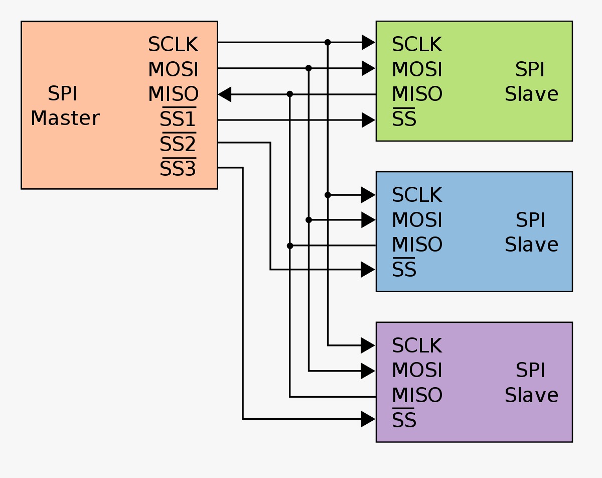
SPI (Serial Peripheral Interface)
SPI is a synchronous serial communication protocol that uses four lines for communication: clock (SCK), master output/slave input (MOSI), master input/slave output (MISO), and slave select (SS).
Advantages:
- High data transfer speed compared to UART and I2C.
- Capable of supporting full-duplex communication. In other words: Both devices can transmit and receive data on media at the same time
- Multiple devices can be connected on an SPI bus.
Disadvantages:
- Requires more connection lines than UART and I2C.
- Not as straightforward to implement as UART due to its synchronous nature.
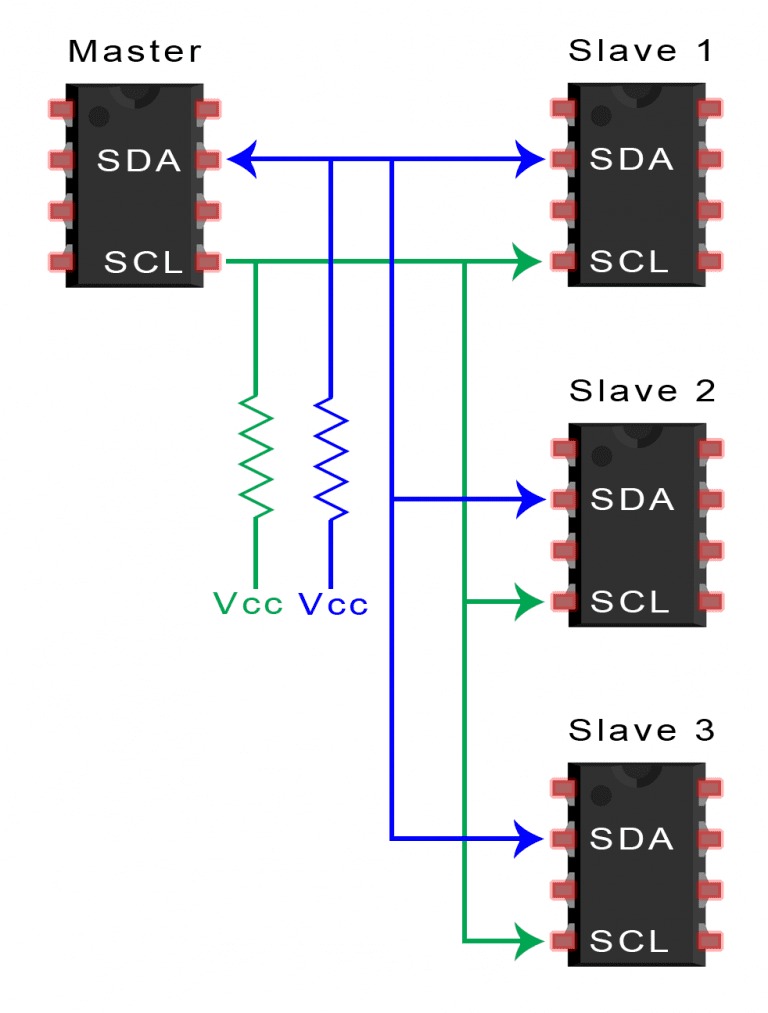
I2C (Inter-Integrated Circuit)
I2C is a synchronous serial communication protocol that uses two lines for communication: a clock line (SCL) and a data line (SDA).
It allows multiple devices to be connected on the same bus.
In I2C communication, pull-up resistors (usually 1kOhm) are used on the data (SDA) and clock (SCL) lines to stabilize the logic high level,
prevent bus conflicts, and control signal transition speed.
Advantages:
- Requires fewer connection lines than SPI.
- Enables communication between multiple devices (master/slave) on the same bus.
- Supports a variety of devices with different slave addresses.
Disadvantages:
- Slower data transfer speed compared to SPI.
- Shorter maximum communication distance compared to UART and SPI.
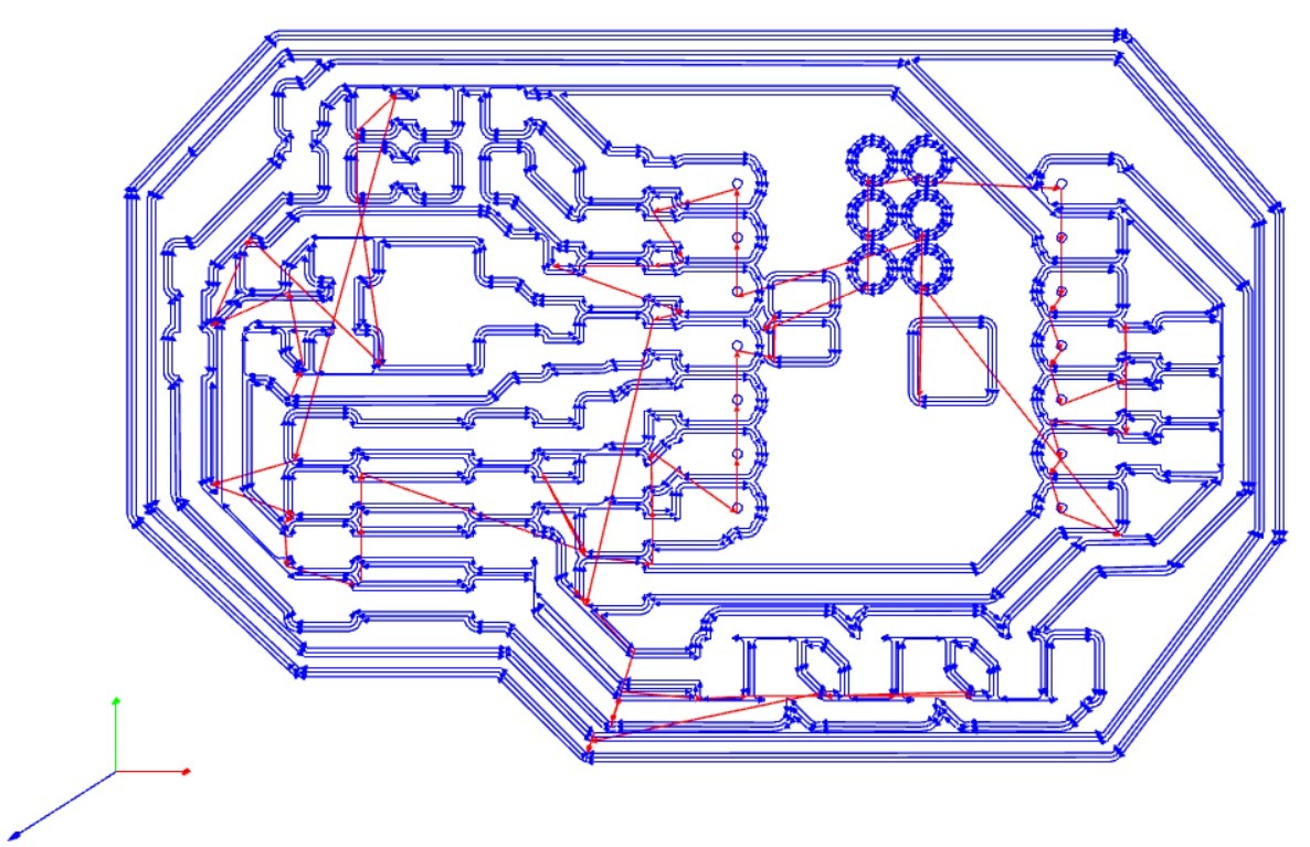
For this assignment I needed a new board, so I designed one for the XIAO ESP32C3. Here are the schequematic and the circuit.
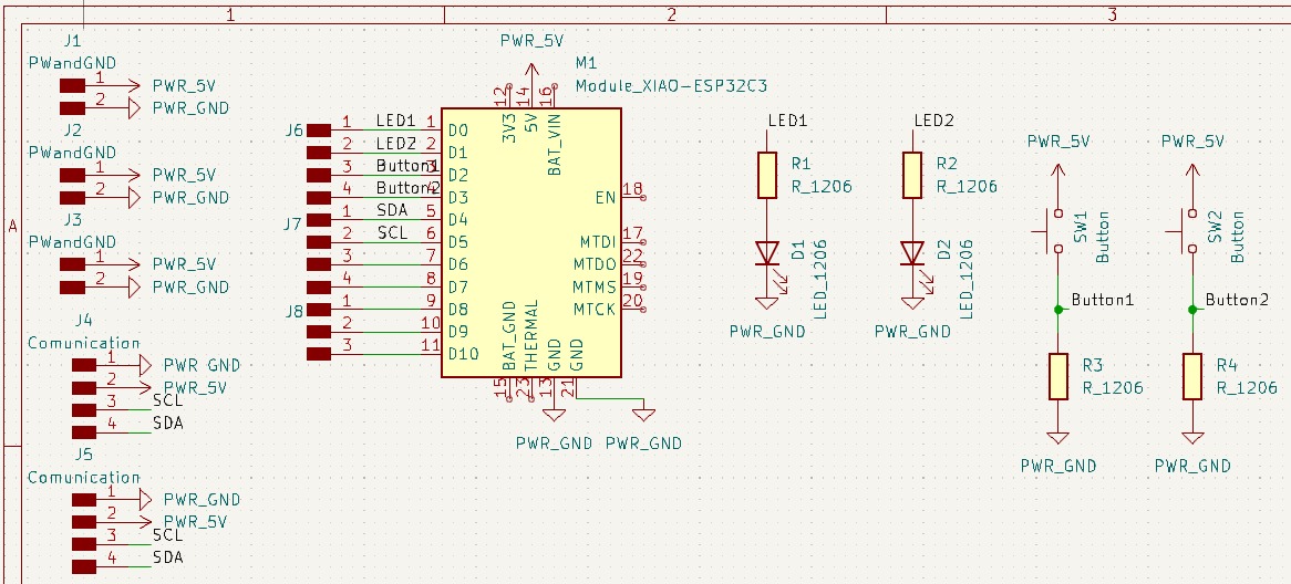
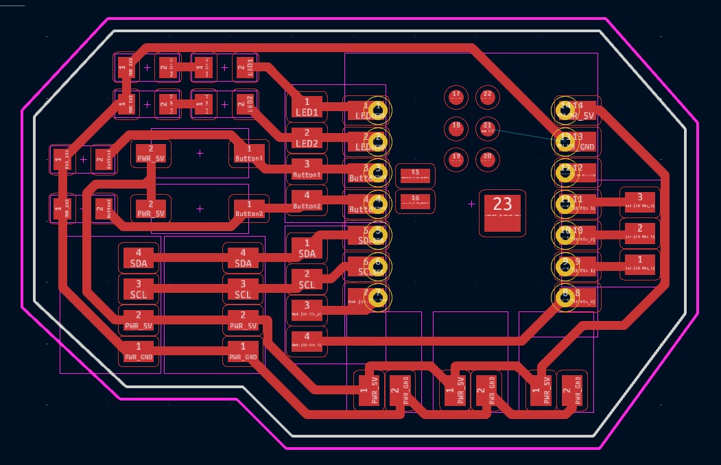
I used previous knowledge using MODS to calculate and generate rml files.

Components list
- XIAO ESP32-C3
- 2 SMD LEDs
- 2 SMD resistors (1001) for the LEDs (1000 ohms)
- 2 buttons
- 2 SMD resistors (222) for the buttons (2200 ohms)
- 25 male pins
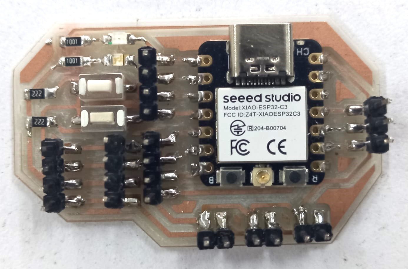
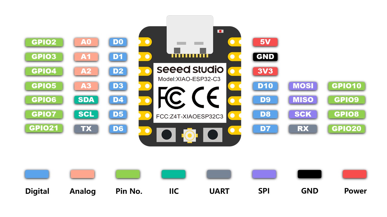
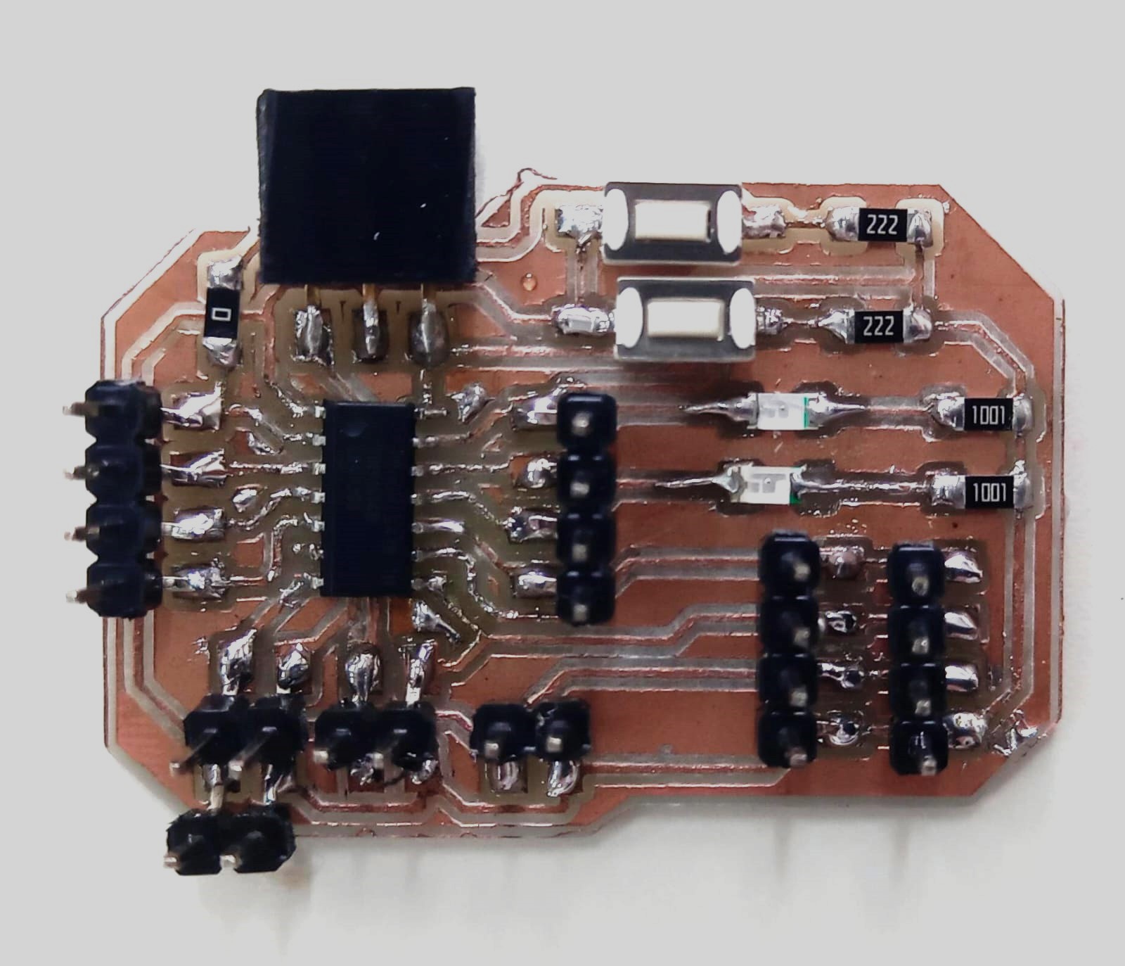
After soldering this is my new board and the pinout ESP32C3.
Likewise, I used my Attiny 1614 (Click here) and Quentorres (Click here) for this week
 Attiny 1614
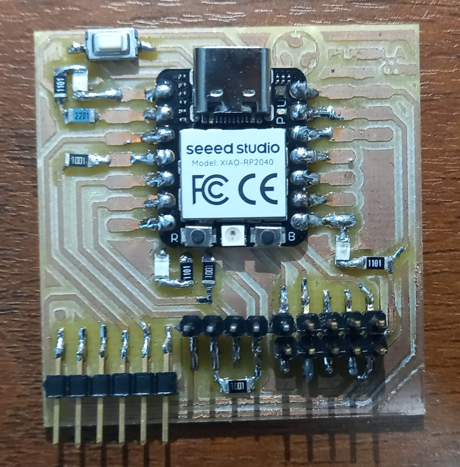 Quentorres
Note: Similar to the Quentorres board, I designed my boards with a pair of communication pins for I2C. In other words, two pairs of four pins dedicated to SDA, SCL, GND, and VCC.
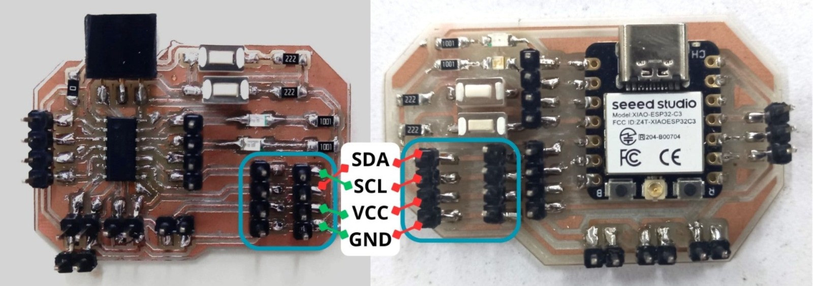
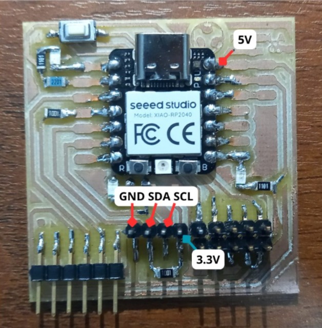
PAY ATTENTION, PLEASE!
The problem I encountered in this assignment was related to voltage. The issue was that the communication pins destined on the Quentorres board has a 3.3V pin (where I connect the wire), while the communication pins on the other boards are powered by 5V. I don't know the exact reason yet, but this voltage mismatch caused a communication problem with the Attiny board. However, I soldered a pin to wire the voltage pin to 5V to resolve the issue.
Communication #1: LED
The communication between the XIAO RP2040 master and the ATtiny 1614 and XIAO ESP32C3 slaves is managed via the I2C protocol. The XIAO RP2040, functioning as the master, monitors the state of a single button. When the button is not pressed, it sends a '0' signal to the slave at address 8 and a '1' signal to the slave at address 9. Conversely, when the button is pressed, it sends a '0' signal to the slave at address 9 and a '1' signal to the slave at address 8. Each slave, upon receiving its respective command, controls the state of its LEDs accordingly. The ATtiny 1614 (slave at address 9) and the XIAO ESP32C3 (slave at address 8) are programmed to respond to these signals by turning their LEDs on or off, thus synchronizing their actions based on the master's input.
Master
Slave 1 Slave 2
Communication #2: Servo
The communication between the ESP32C3 master and the ATtiny 1614 and XIAO RP2040 slaves is established via the I2C protocol. The ESP32C3, acting as the master, reads the states of two buttons. When a button is pressed, it sends specific commands ('A' to increase the servo angle by 5 degrees, 'R' to decrease it by 5 degrees) to the respective slaves. Each slave device, upon receiving a command, adjusts its servo motor and LED states accordingly. The ATtiny 1614 and XIAO RP2040 slaves are configured to listen for these commands on their unique I2C addresses (9 and 8 respectively) and perform the instructed actions, thereby synchronizing the movements and LED indications in response to the master's inputs.
Master
Master
Master
Slave 1 Slave 2
Files
Each zip file contains master, slave 1 and slave 2 codes.