4. Electronics Production
First of all, in our group webpage, we explain about PCB milling. Where we cover topics such as what PCB milling is, materials, safety guidelines, tooling, some aspects of the process, and more! Please make sure to verify your model and its characteristics before starting.
Our FabLab uses this machine: ROLAND SMR-20
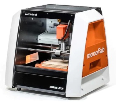
PCB milling is used to make circuit boards. A rotary cutter carves away the copper path, creating circuit traces. So... where do we start?
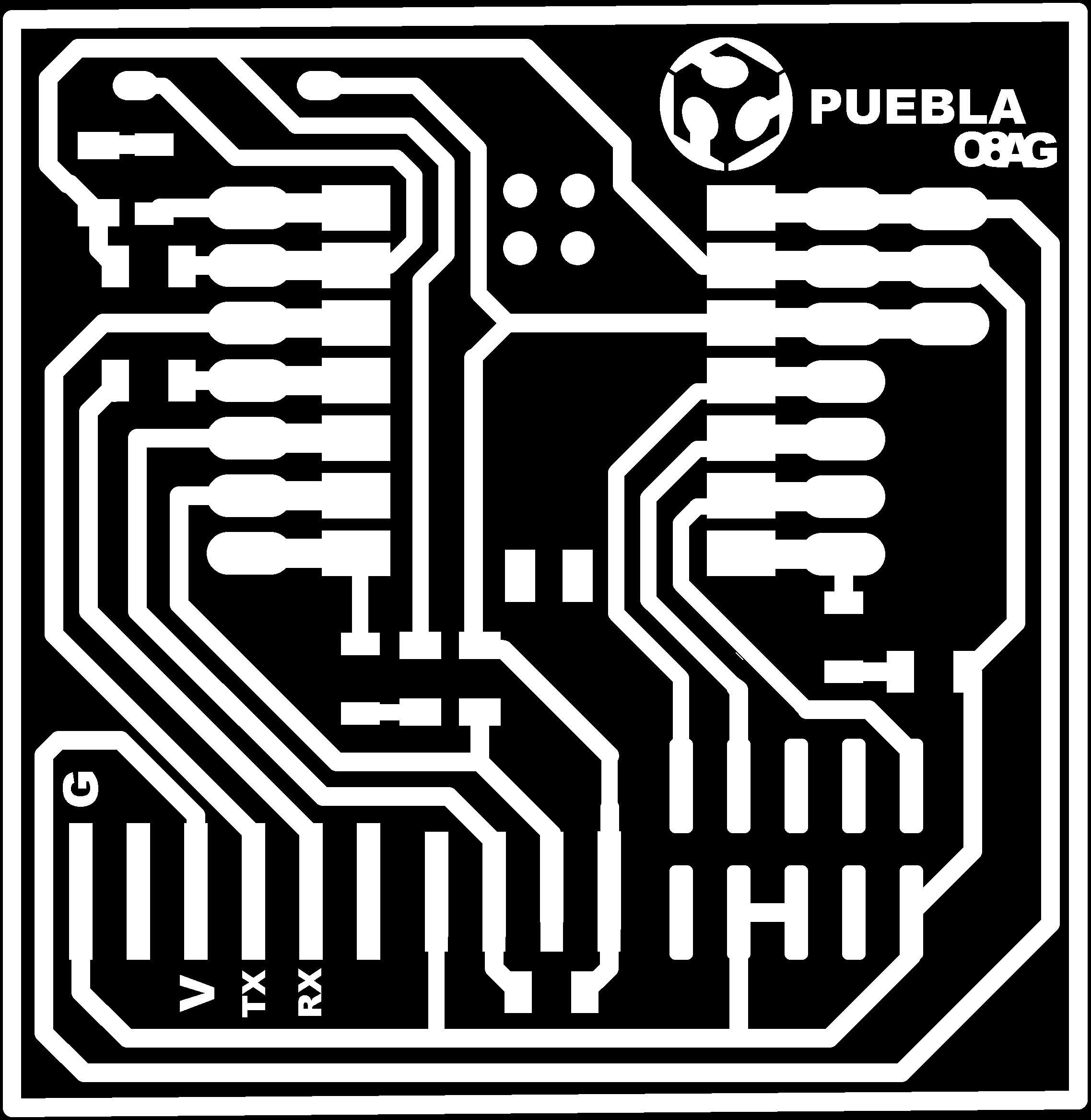
First of all, we need two images in PNG format: traces and outline cut (these are in files section).
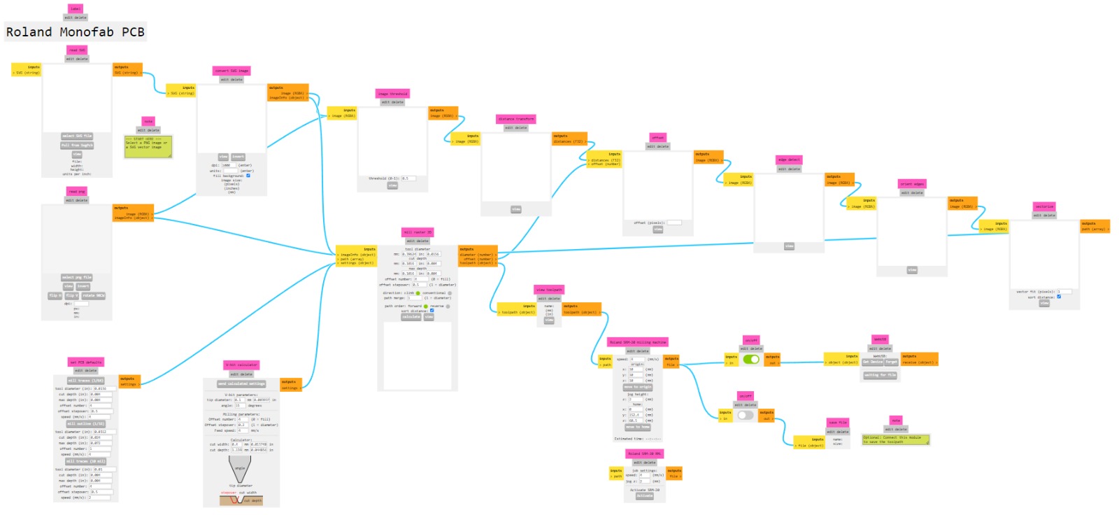
Toolpath creation
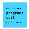
Access in MODs page

Then right-click on the screen and following the next route.
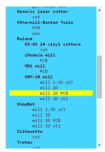
Programs -> open program -> in Roland section/SRM-20 mill choose mill 2D PCB
Looks catastrophic and complicated, but don't worry is easier than you expect.
Traces
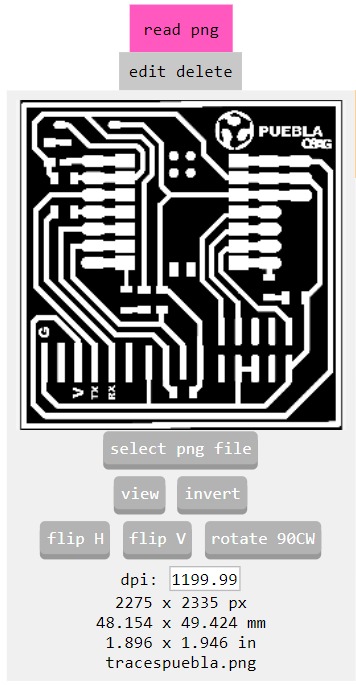
1. Select the traces png file
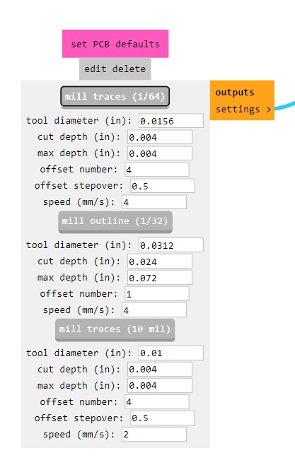
2. Click on mill traces 1/64
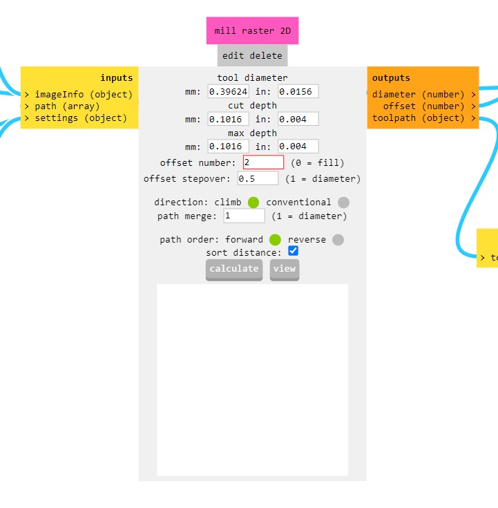
3. Change offset number to 2
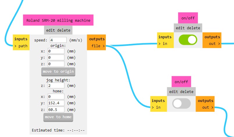
4. Set x, y and z origins to 0
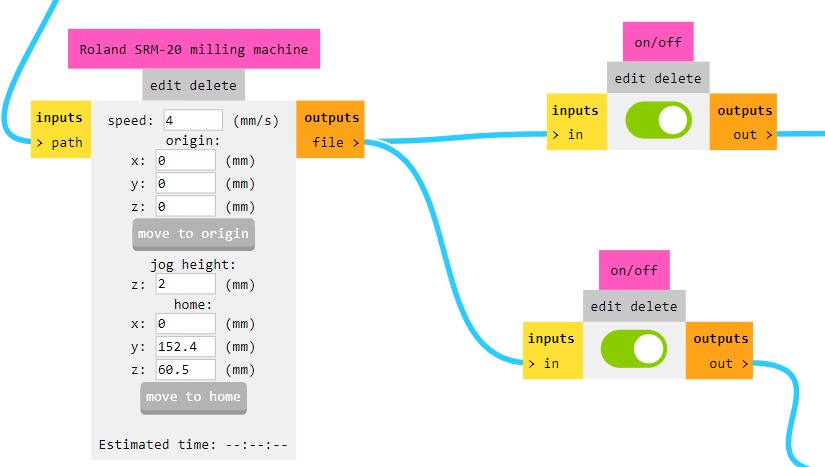
5. and turn on "edit delet"
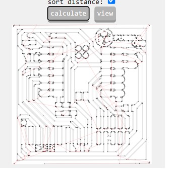
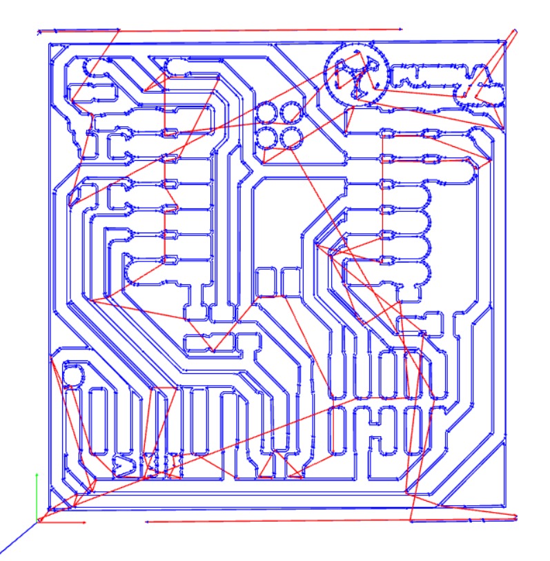
6. Calculate traces
This way you get the rml file
outline
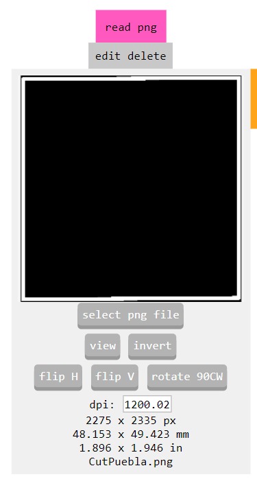
1. Select the outline png file
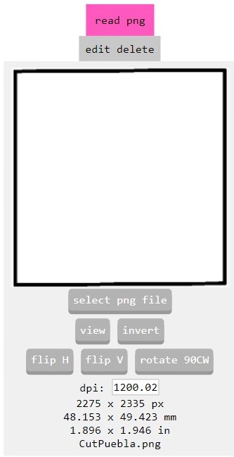
2. Click on invert
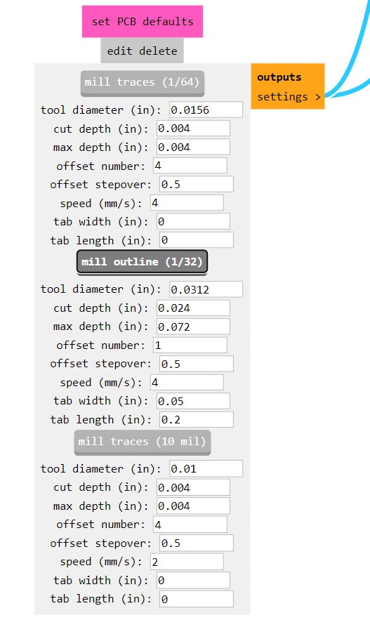
3. Select mill outline 1/32 and automatically changes offset number to 1
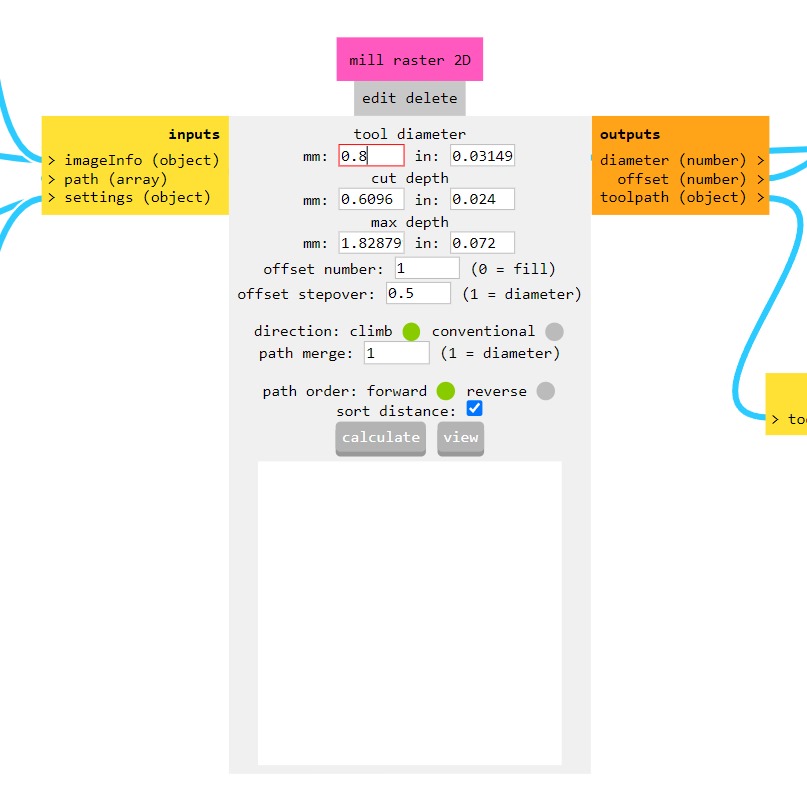
4. Set tool diameter to 0.8 mm
5. Keep all configurations unchanged
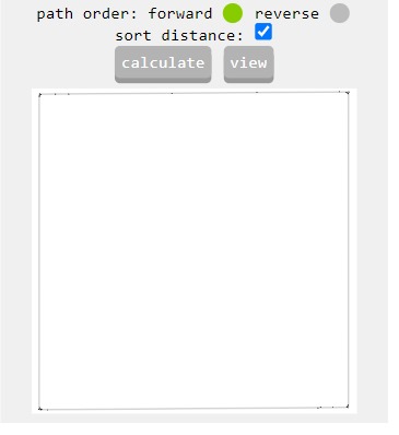
6. Calculate outline
This way you get the rml file
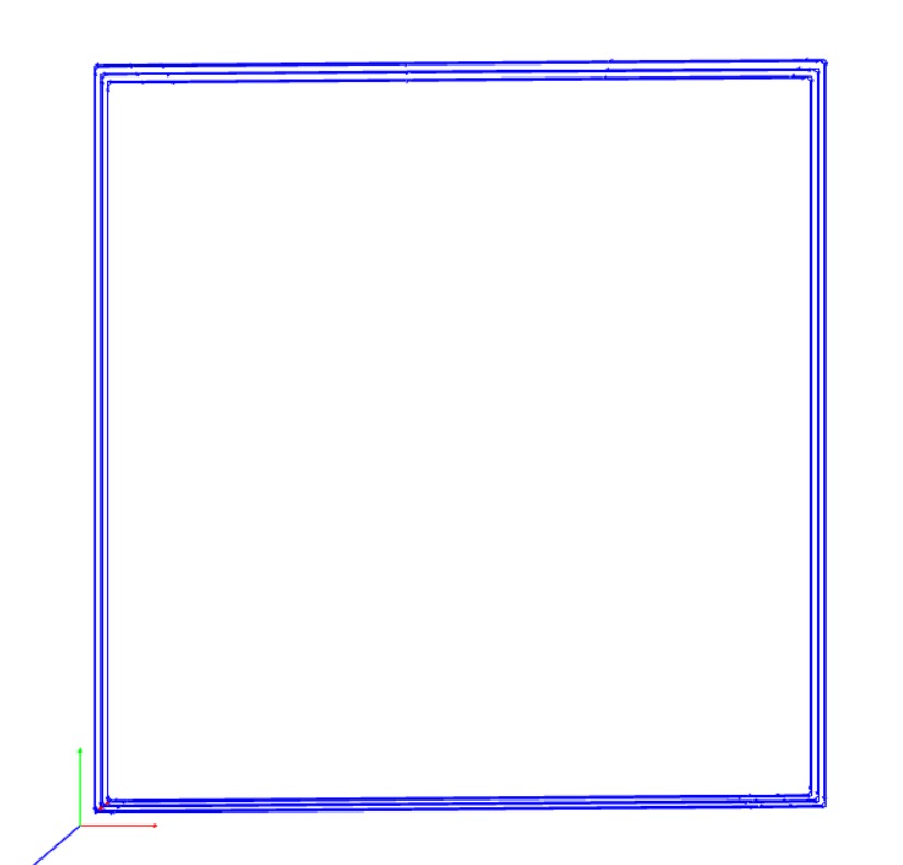
IMPORTANT if you don't click on invert outline image, you will get a wrong rml file. Since PCB milling machine will cut the edges of the outline. Like this:
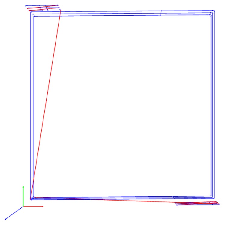
Bad outline
Equal a bad cutting
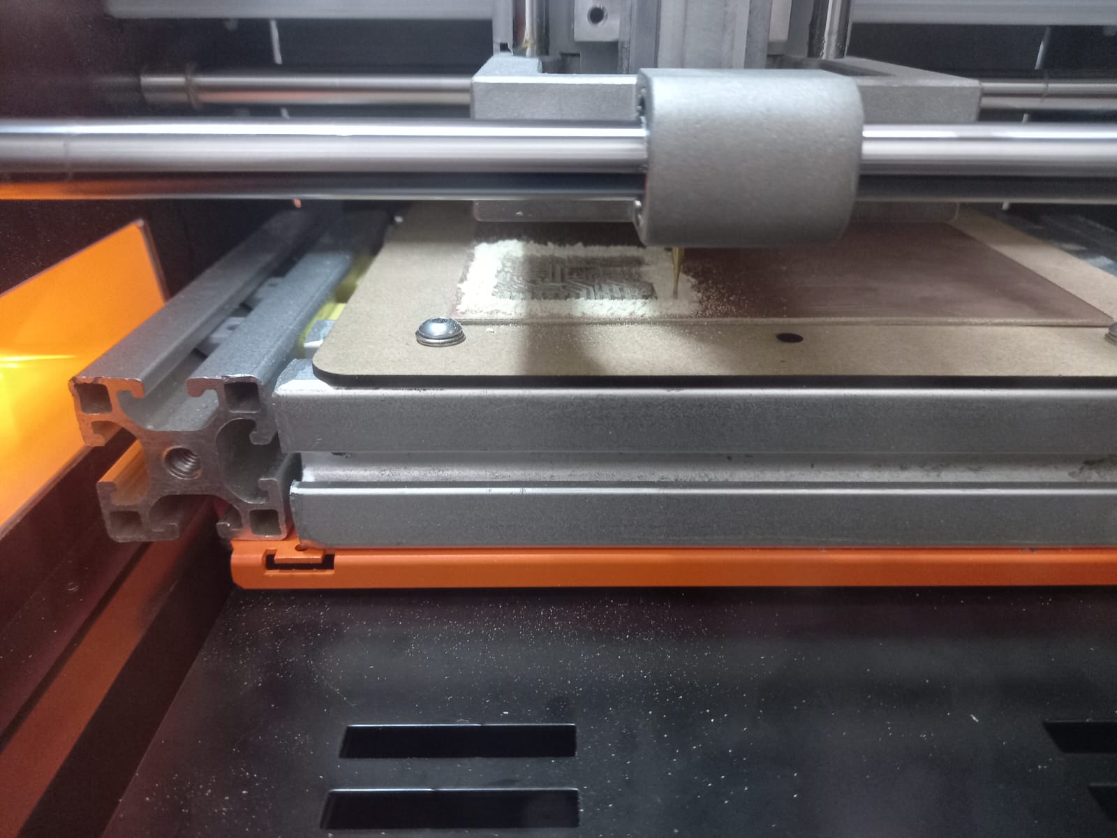
PCB Milling
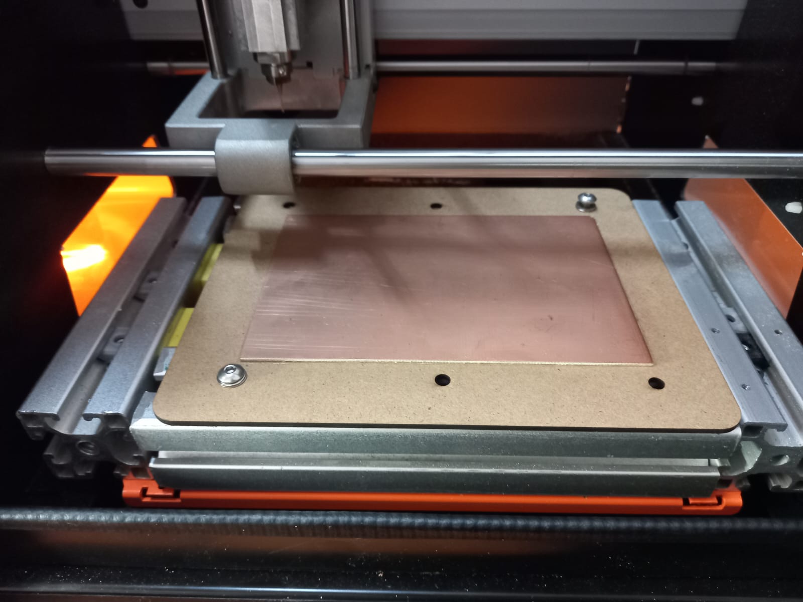
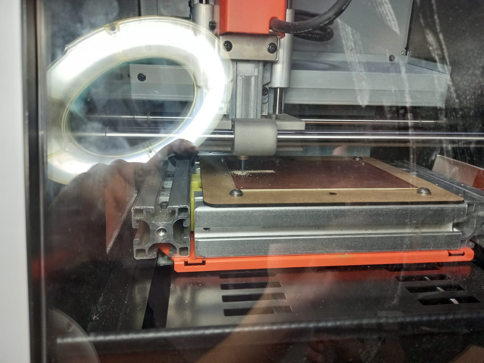
I placed double-side tape on my copper plate to stick it onto an MDF board, aiming to avoid cutting into the metal base of the machine in case I went too deep. Later, I secured my board to the machine with screws.
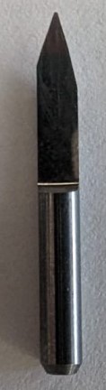
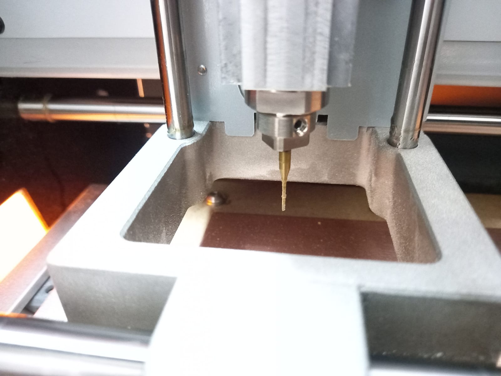
So, before to cut I place the V-bit tool in the machine for engraving.
Steps to prepare mini mill machine (CNC)
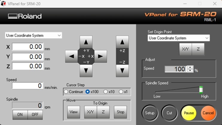
- Download and install the driver and Vpanel software.
- Turn on and connect cables to the computer.
- Set origin in the x and y axis.
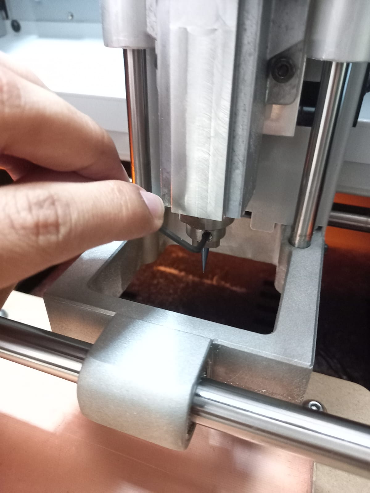
- If you lower too quickly on the Z-axis, the tool may break. Therefore, use microns (x1) when you are close to the board. I placed a paper under the tool to ensure it was well-positioned.
- Once the tool is over the board, activate the tool with the spindle option when it reaches 8000 revolutions per minute. Lower it by 1 to 2 microns. At this point, set the origin z-axis.
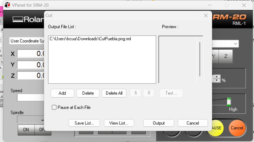
- Upload (add) your file and start to cut (output).
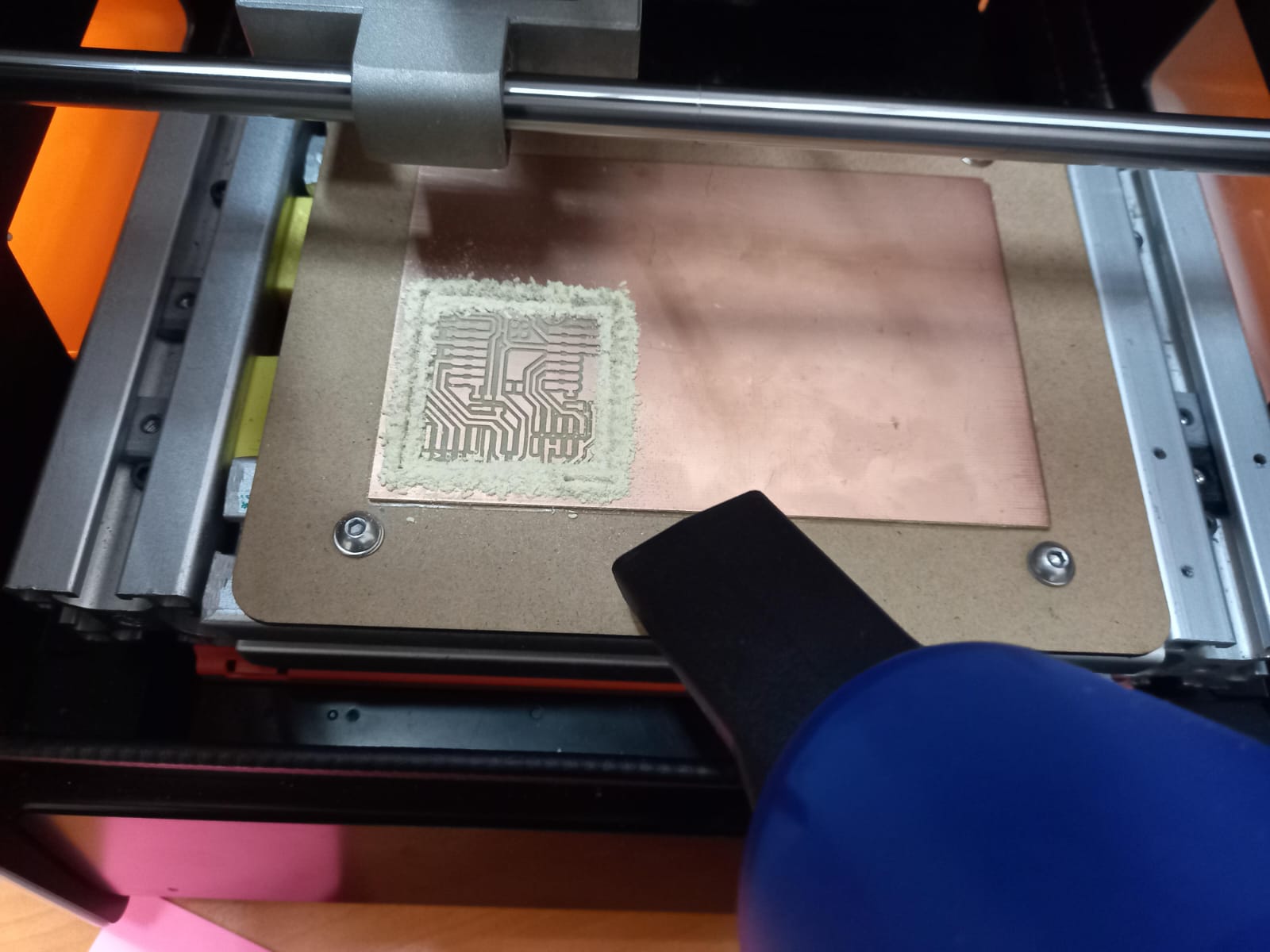
After the process, be sure to clean up.
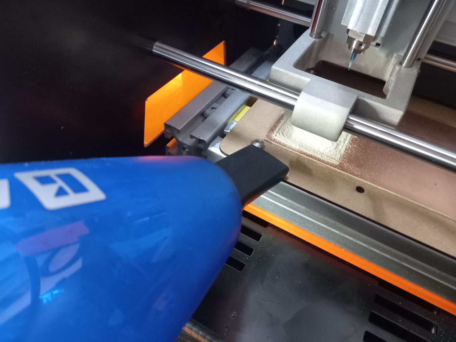
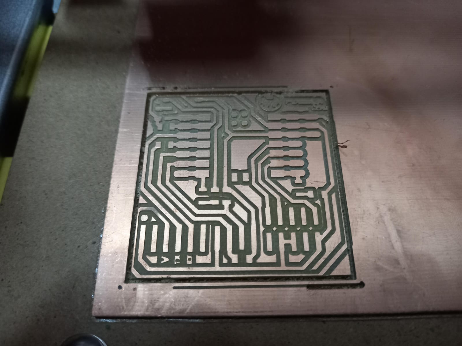
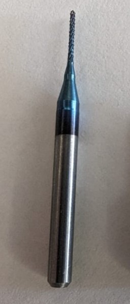
Change the V-bit tool to a two-flute end mill for cutting, and then begin the cutting process.
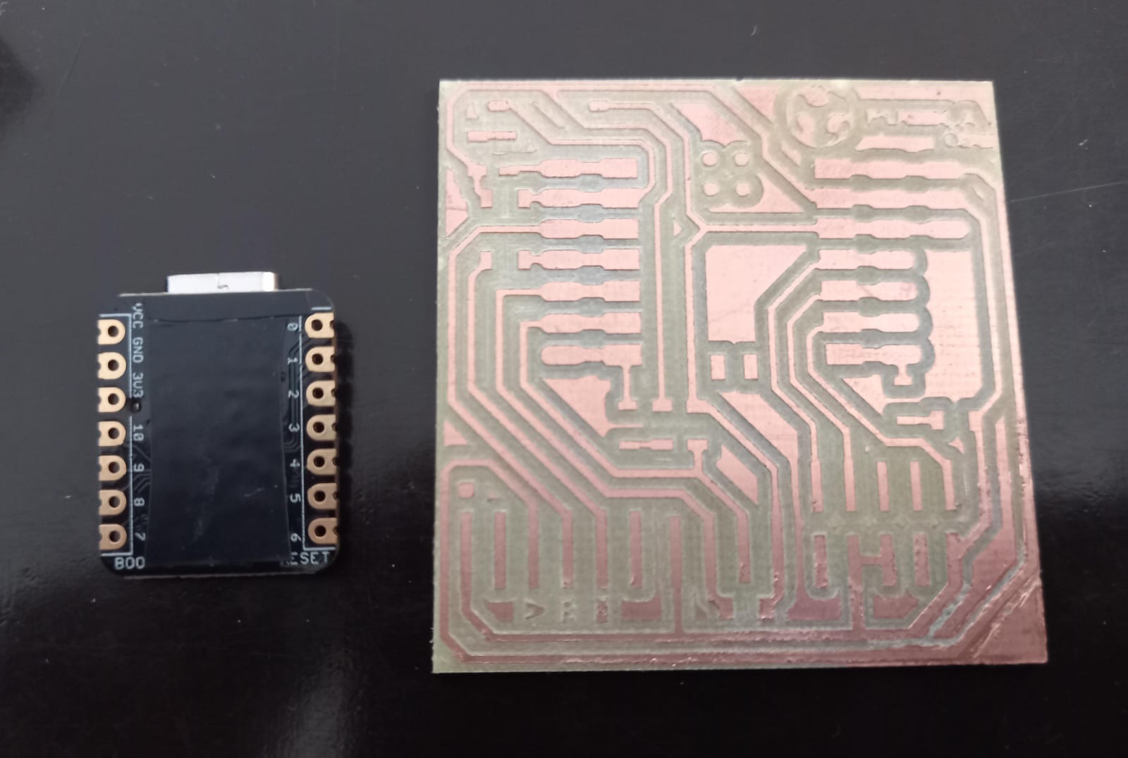
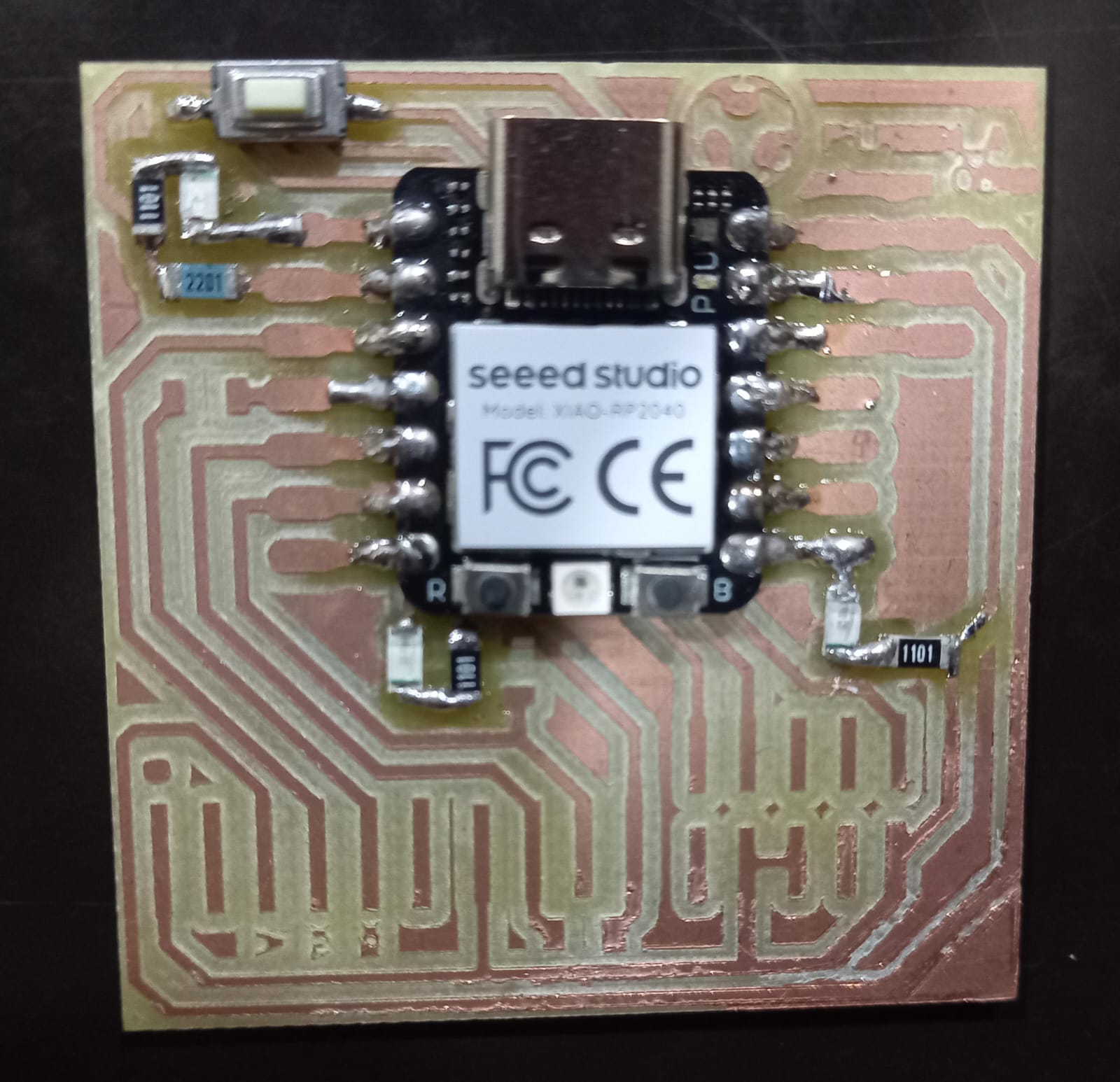
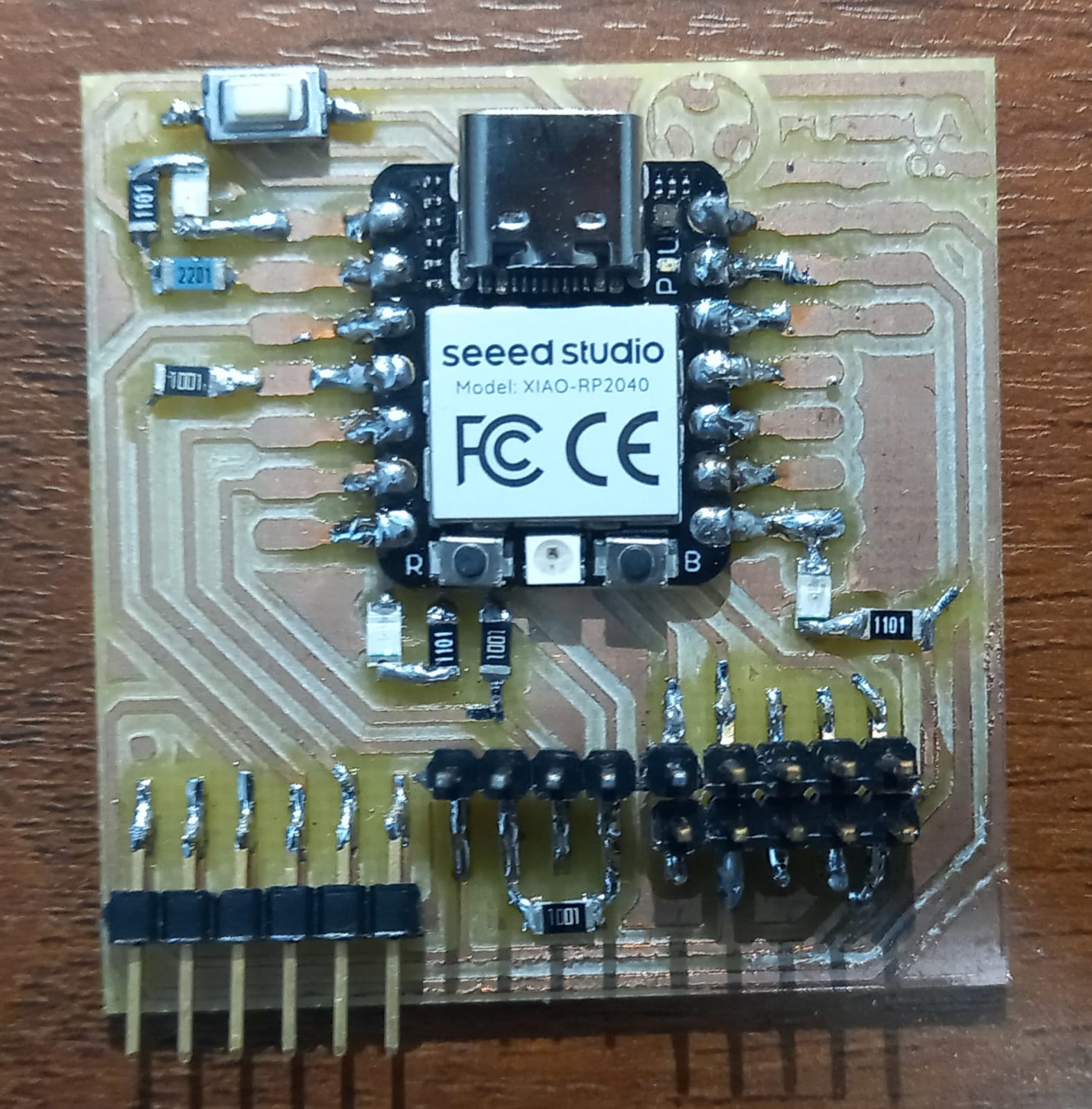
Excellent! Now, we have our PCB. I applied some electrical tape behind my chip to safeguard the connections underneath.
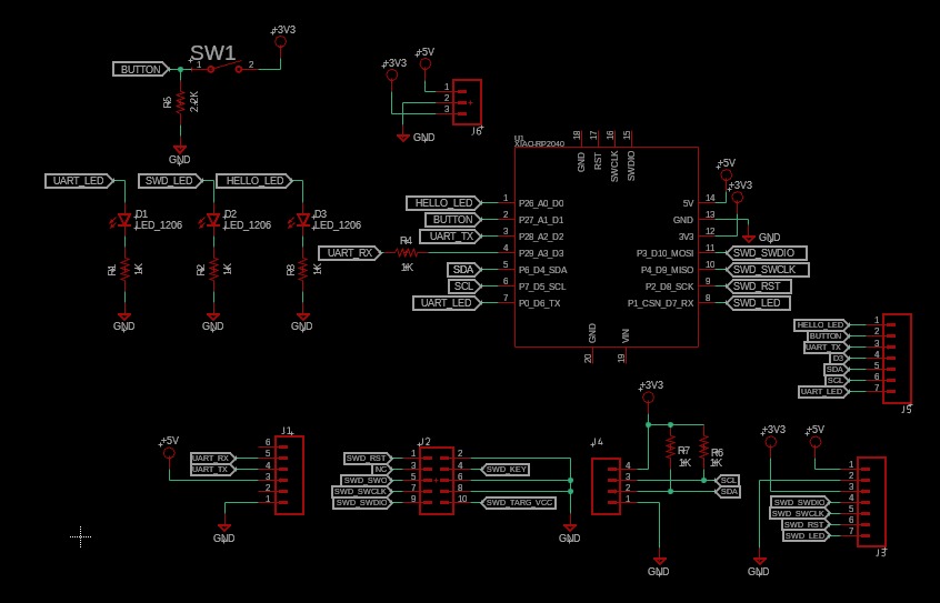
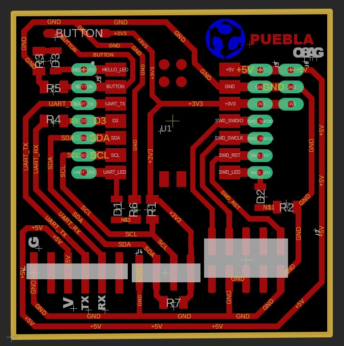
Before soldering, review the schematic file and the circuit diagram.
It's time to solder.
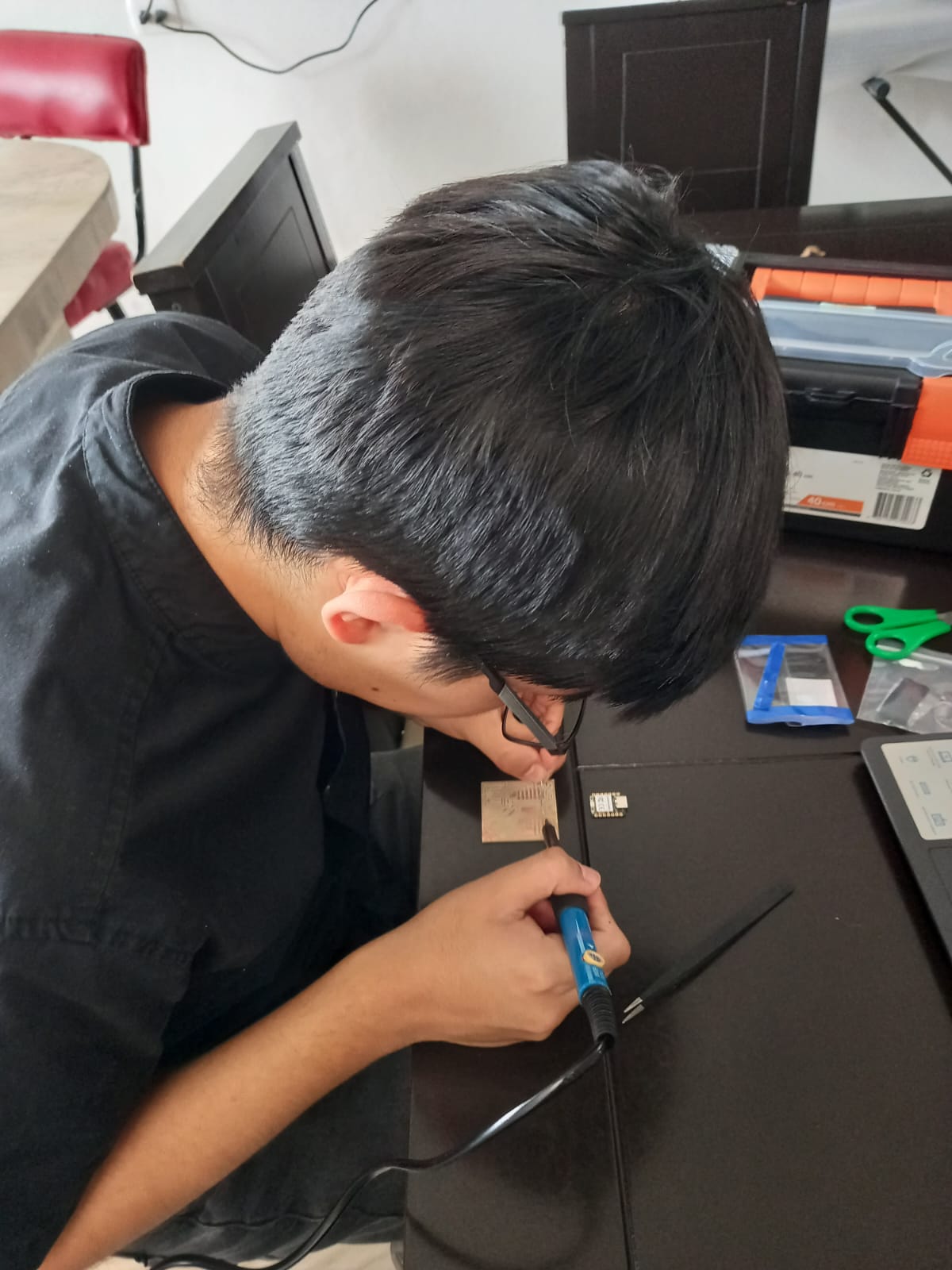
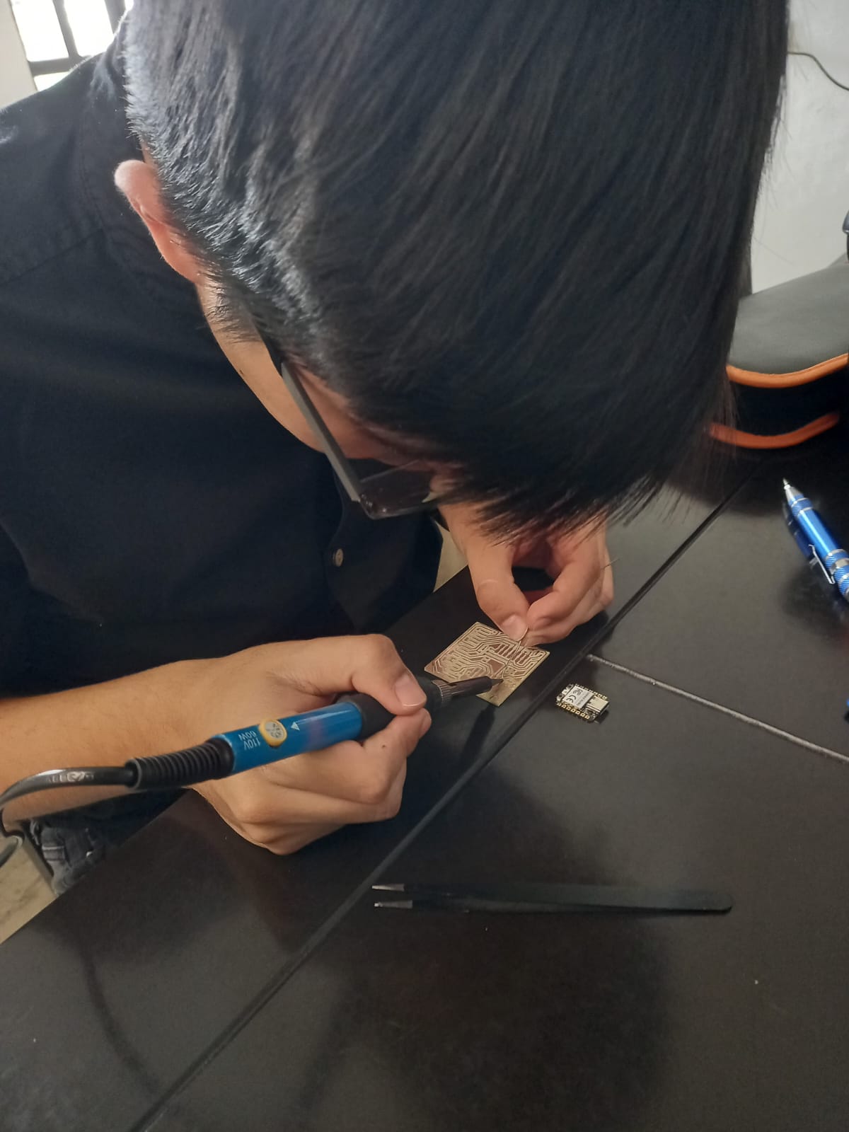
Perfect! I suggest starting by soldering the processor and then the smaller components. For the latter, it's helpful to apply solder to the board first and then only heat it when placing the components.
Code and testing
Here is the web tutorial to connect the Seeed Studio XIAO RP2040 to the computer and upload a simple code from Arduino to check whether the board is functioning well.
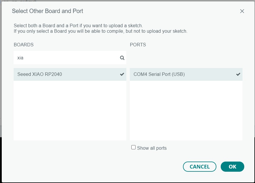
After all, connect your circuit to the computer and then choose the port in the Arduino software.
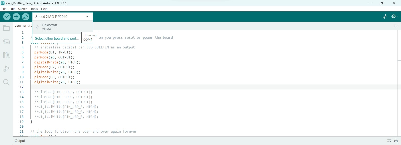
In boards, choose Seeed XIAO RP2040.
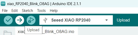
Then upload the code, which you can find in the file section.
Testing
And finally:
Files
- CutPuebla
- TracesPuebla
- CutPuebla.rml
- TracesPuebla.rml
- Blink code