My Final Project
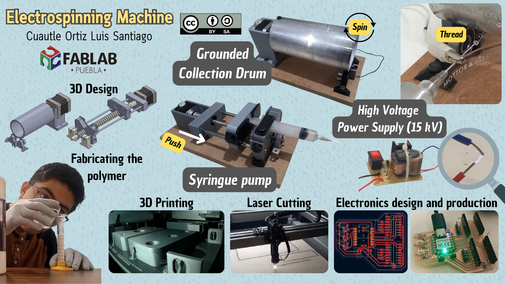
Slide
Video
Sketch
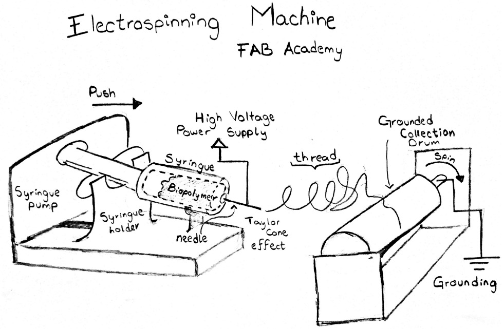
An electrospinning machine is a device that use electricity to transform viscous polymer liquids into an extremely thin and fine fiber. In this process, the liquid is extruded through the electrically charged needle. The electric charge generates electrostatics forces, resulting in the formation of threads that are collected by a Grounded Collector Drum. This device can be used by biomedical engineers in the following applications:
- Tissue engineering scaffold.
- Advanced dressings and bandages.
- Controlled drug release devices.
- Biocompatible implants.
- Filters and membranes for biomedical applications.
- Biomedical sensors.
Research
Previous works
- Diseño y construcción de una máquina de electrohilado vertical de 0 a 15 KV para generar nanofibras a base del polímero polisiloxano
- Construcción de un sistema de electrospinning para la obtención de fibras poliméricas: control y caracterización.
- Electrospinning vs Electrospraying para la optimización de los parámetros de deposición en el diseño de recubrimientos nanoestructurados de uso biomédico
Materials
| Qty | Description | Price | Link |
|---|---|---|---|
| Syringe Pump | |||
| # | PLA Filament | $346 MXN - $18.5 USD | https://www.inovamarket.com/p/filamento-pla/ |
| 2 | Steel smooth rods 8mm | $63 MXN - $3.5 USD | https://es.aliexpress.com/item/1005003040410825.html?src=google |
| 1 | Endless Screw Rod | $200 MXN - $10.85 USD | https://articulo.mercadolibre.com.mx/MLM-2638265386-tornillo-8mm-x-300mm-4-hilos-paso-8-mm-cnc-impresora-3d |
| 2 | Linear bearings | $25 MXN - $1.5 USD | https://es.aliexpress.com/item/LM8UUAJ-8mm-lineal |
| 1 | Pillow block bearing | $17.12 MXN - $1 USD | https://es.aliexpress.com/item/almohada-aleación de ZINC-8mm |
| 1 | Stepper Motor | $250 MXN - $13.5 USD | https://www.steren.com.mx/motor-a-pasos-nema-17.html |
| 1 | Stepper Motor Coupler | $59 MXN - $3.2 USD | https://articulo.mercadolibre.com.mx/MLM-861821928-cople-flexible/ |
| 2 | Screws M5 1 inch | $4.5 MXN - $0.24 USD | At your nearest hardware store |
| 4 | Screws M10 1/2 inch | $20 MXN - $1 USD | At your nearest hardware store |
| 1 | Screws M8 1/2 inch | $3.5 MXN - $0.2 USD | At your nearest hardware store |
| 1 | Hex Nut M8 1.25 | $4 MXN - $0.25 USD | At your nearest hardware store |
| 2 | Syringes and needle 20 ml | $30 MXN - $1.65 USD | https://www.farmaciasguadalajara.com/salud-es/curaciones-es/jeringas-y-agujas-es/jeringa-20ml |
| Grounded Collector Drum | |||
| 30 cm | Aluminum cylinder with a 2 1/2 inch inner diameter | $170 MXN - $9.2 USD | In your preferred metal supply group |
| 2 | Motor brush | $20 MXN - $1 USD | You can find it cheaper at a hardware store. |
| 1 | Stepper Motor | $250 MXN - $13.5 USD | https://www.steren.com.mx/motor-a-pasos-nema-17.html |
| 2 | Bearings 10 mm inner diameter | $31.5 MXN - $1.7 USD | https://es.aliexpress.com/item/Rodamiento-de-10-piezas |
| 6 | Screws M5 1/2 inch | $15 MXN - $0.8 USD | At your nearest hardware store |
| 10 cm | Wire | -- | Provided by the university |
| High-voltage Power Supply | |||
| 2 | High-voltage power supply 15Kv | $166 MXN - $9 USD | https://www.amazon.com.mx/generador-encendedor-desmontadas-15kv |
| 10 cm | Wire | -- | Provided by the university |
| Box | |||
| 1 | 3 mm MDF panel | $145 MXN - $7.9 USD | https://www.homedepot.com.mx/p/arauco-mdf-3mm |
| 2m | Wire | $20 MXN - $1 USD | https://www.homedepot.com.mx/p/indiana-cable |
| 1 | Plug | $35 MXN - $1.9 USD | https://www.homedepot.com.mx/p/arrow-hart-clavija-angular |
| 1 | 12 volt source | $125 MXN - $6.8 USD | https://articulo.mercadolibre.com.mx/fuente-conmutada-de-alimentacion-12v |
| 1 | XIAO RP2040 | $350 MXN - $19 USD | https://articulo.mercadolibre.com.mx/raspberry-pi-pico-rp2040-xiao |
| 1 | Lithium battery 3.7 V with its charger | $100 MXN - $5.4 USD | https://articulo.mercadolibre.com.mx/bateria-de-litio-lipo-37v-800mah |
| 2 | Charge module for Lithium battery 3.7 V | $40 MXN - $2.2 USD | https://articulo.mercadolibre.com.mx/2-piezas-modulo-tp4056-usb-tipo-c |
| Polymer | |||
| # | Expanded Polystyrene | $13 MXN - $0.71 USD | https://www.officedepot.com.mx/officedepot/placa-de-unicel |
| 1 | Bottle of Thinner | $60 MXN - $3.25 USD | https://tienda.comex.com.mx/producto/solventes/19A0667305 |
| Total: $2565 MXN - $138.75 USD | |||
Week 02
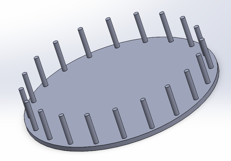
Speaking with the biomass laboratory team, we agreed to make changes to the initial sketch. We would implement the centrifugal spinning variant of electrospinning, which promises to be more effective in obtaining more thread in less time and in greater quantity. To achieve this, I sketch the thread circular collector.
And the syringue pump.
Remodel
Syringue pump
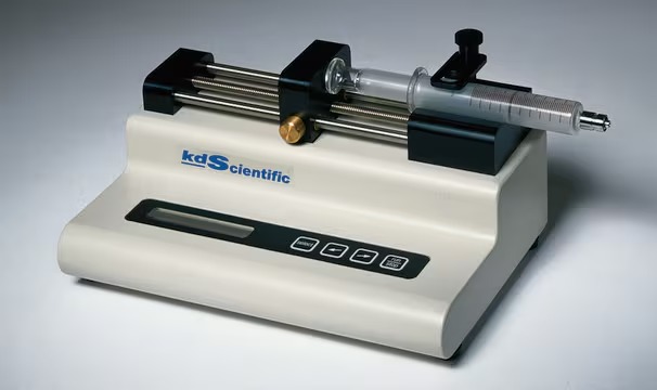
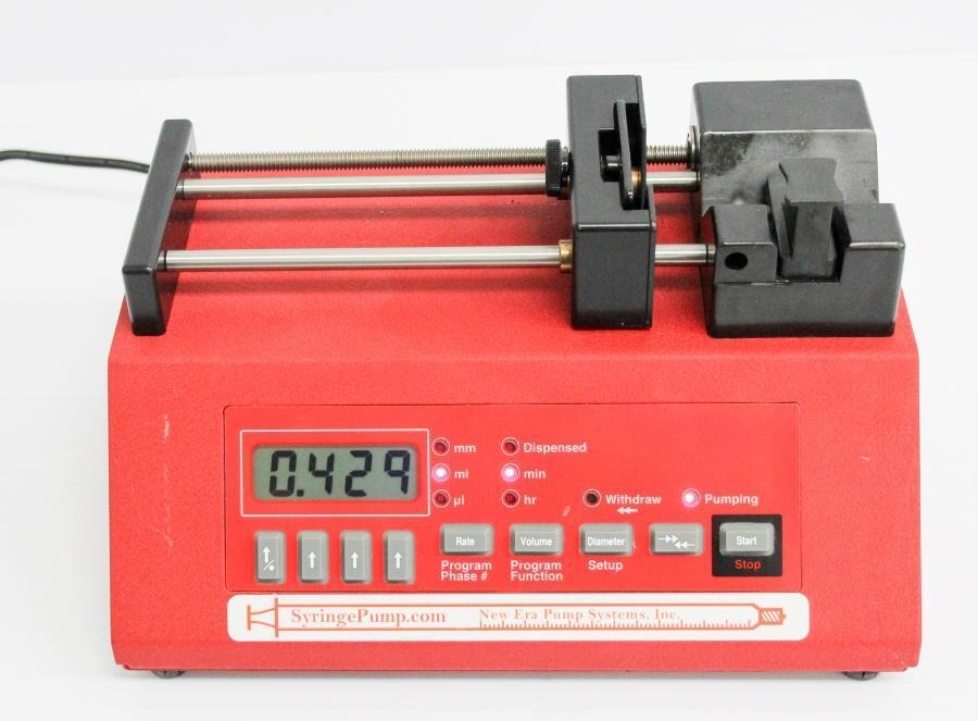
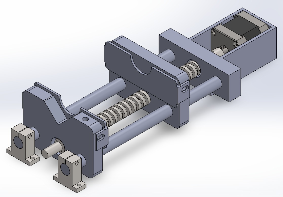
I decided to return to the initial prototype (image above) because we wanted to understand the action of electrostatic interactions to overcome the surface tension of the polymer solution. So, I proceeded to design a syringe pump in SolidWorks. I decided to use the most common mechanism on the market because it was very similar to the one we used for our CNC in week 10.
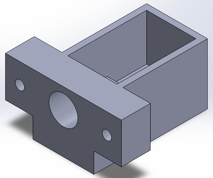
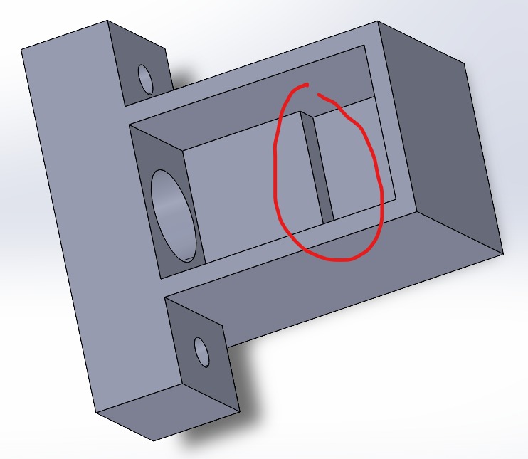
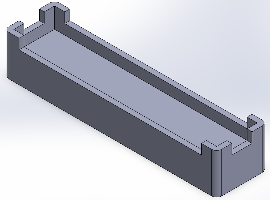
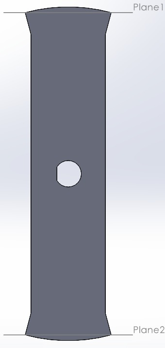
I measured the parts I would use with a caliper to ensure they fit precisely. This piece was designed with two holes at its ends where the two steel smooth rods will be placed to connect the other parts of the pump and allow the syringe to slide. Additionally, the middle hole is larger to accommodate the motor coupling with the endless screw. In the second image, you can see that I added a small step to prevent the motor's vibration from displacing it.
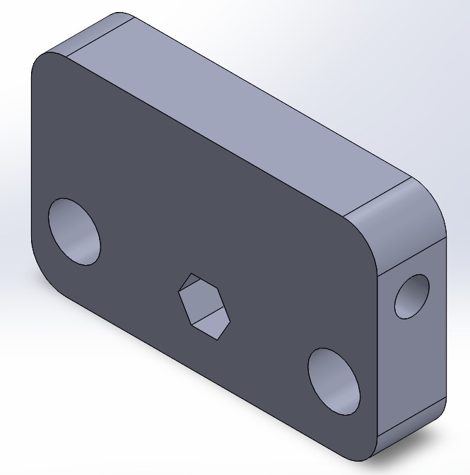
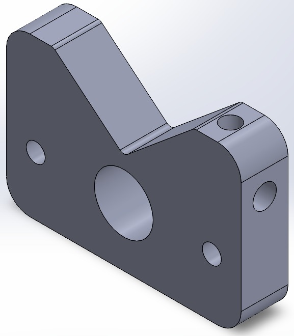
This piece was designed to move, so at its ends, we have larger holes to fit the linear bearings that will allow sliding on the steel smooth rods. There is also a hexagonal center for the endless screw that will be connected to the motor. On the sides of this piece, there are holes that will hold the part securing the syringe to the pump with M10 screws.
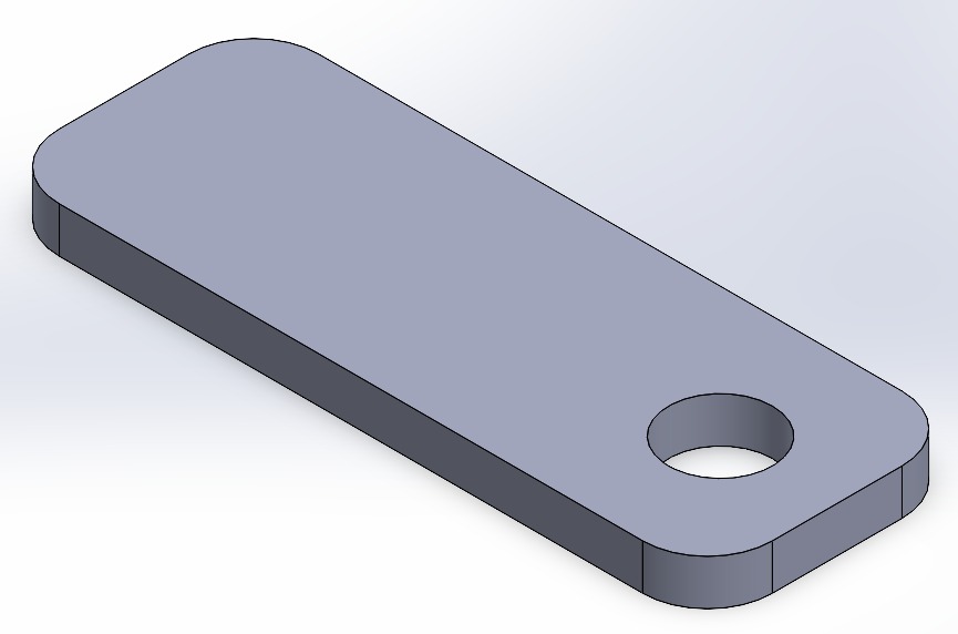
These two clamps will hold the syringe's plunger base and the support flange, thanks to the screws that will be placed on the sides of the parts. This ensures that the motor's force is concentrated on extracting the polymer and keeping the syringe in place.
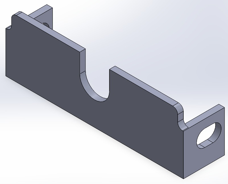
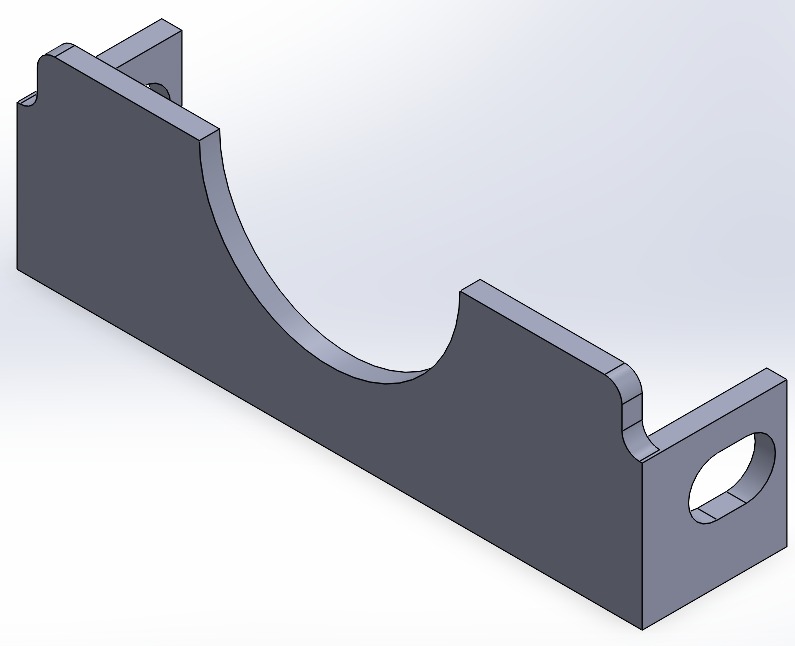
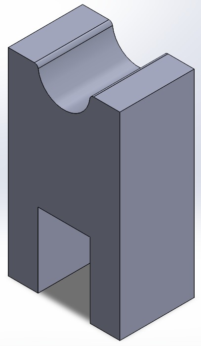
This piece will be at the end of the syringe pump, where the endless screw will be connected to a bearing, and the steel smooth rods will fit snugly. Here, the syringe will rest, and there will be side holes to secure it with screws. At the top, there is another clamp to prevent vertical oscillatory movement of the syringe.
After 3D printing and assembling the parts, I noticed that it was not well aligned with the surface, meaning it was lifted by the motor and metal weight by about 1 cm. So, I made a small piece to correct this, which also made it look cooler.
3D Model: Syringue pump
This is how the assembly of all the pieces looks in SolidWorks:
The manufacturing of this piece was as follows:
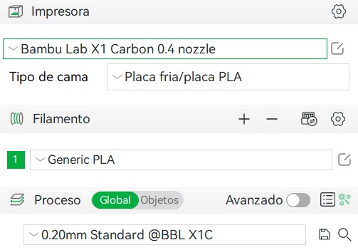
PLA and a Bambu Lab X1 Carbon printer were used for printing the parts. The following settings were used: a 0.4 nozzle, Generic PLA, and 0.2 mm Standard. From there, the machine's default settings were utilized. The documents are saved and inserted into an SD card, although it is important to note that unlike the machine used during the print week, the print bed requires a bit of glue stick to prevent the parts from moving.
The Bambu printer is super fast and very good compared to the Ender, as all my parts were printed within 6 hours! (Video)
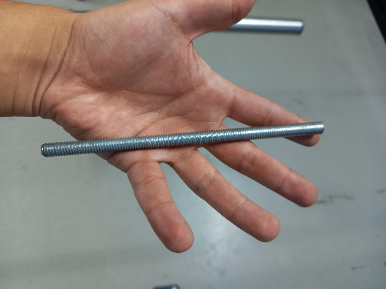
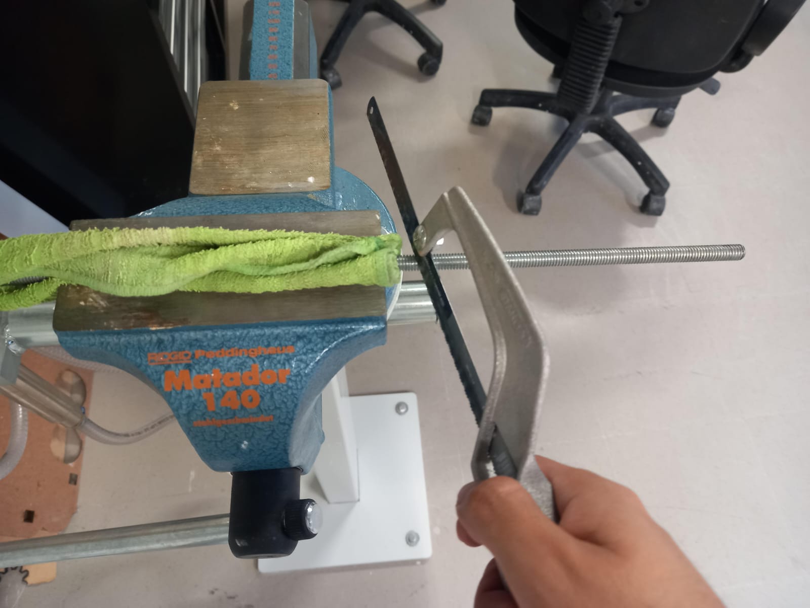
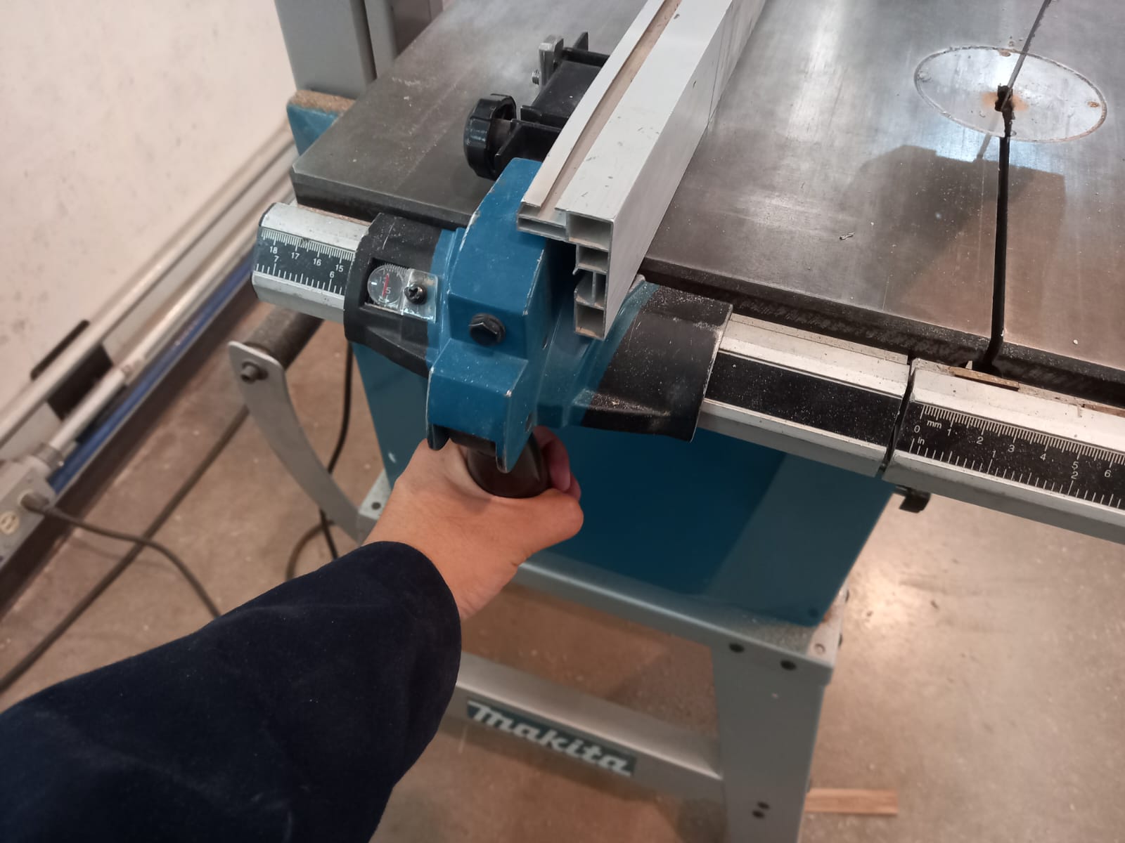
I marked the endless screw and the steel smooth rods with a permanent marker to cut them to measurements of 24 cm and 20 cm, respectively. I used a handsaw and secured them in a vice for a cleaner cut. To prevent marks from the vice, I protected the rods with a cloth and proceeded to cut along the marks made with the permanent marker.
However, not everything is perfect. One problem I encountered was the tolerances for the steel smooth rods, as the holes in the parts were too exact. I increased the diameter by 0.5 mm to avoid the issue. Everything else fit as planned, such as the linear bearings. (steelrods, linearbearings, finalfit)
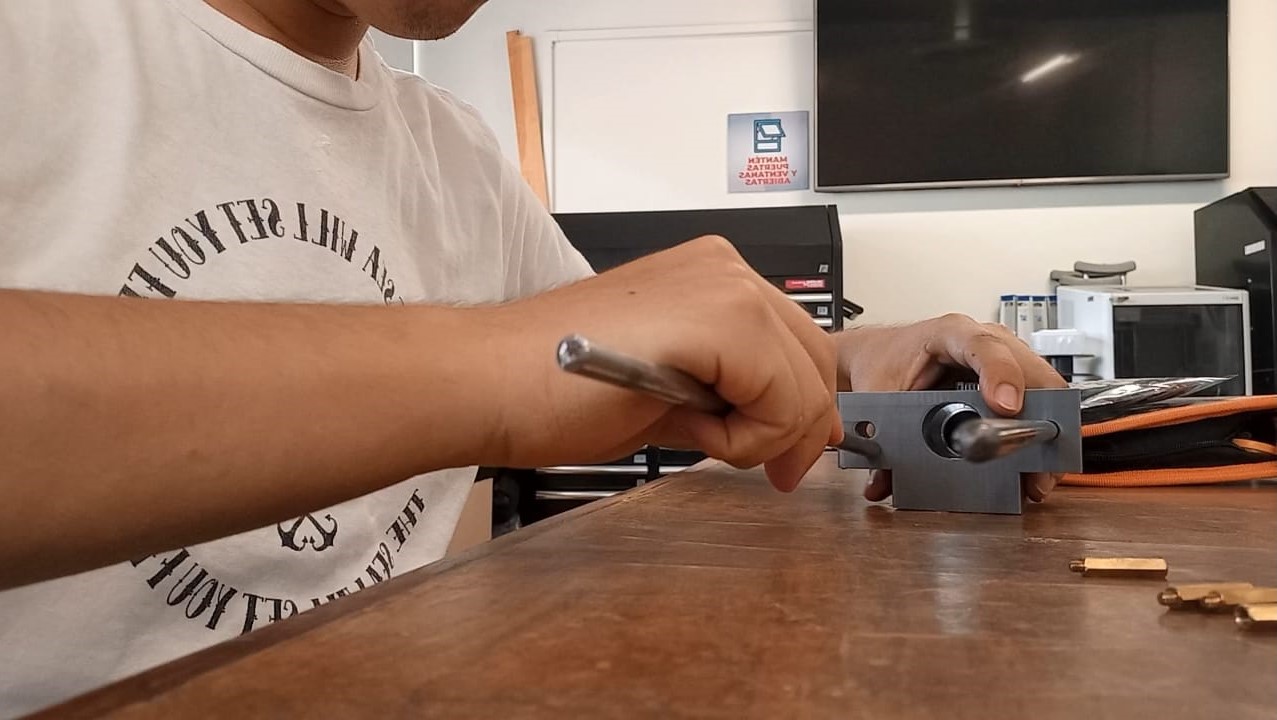
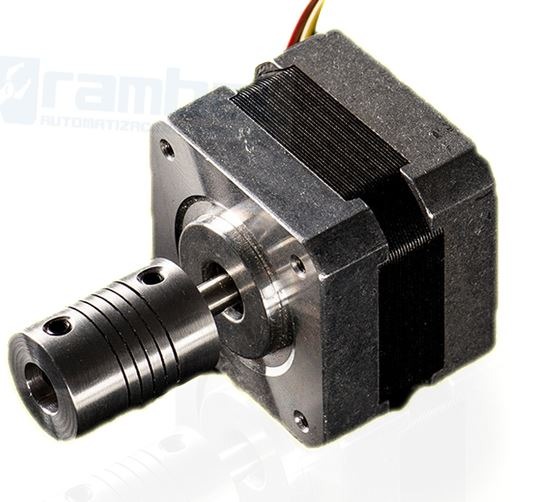
It is important to mention that for the motor, I used a coupling and placed a bearing at the end of the endless screw. (I later realized the bearing was not necessary, but I left it in place anyway).
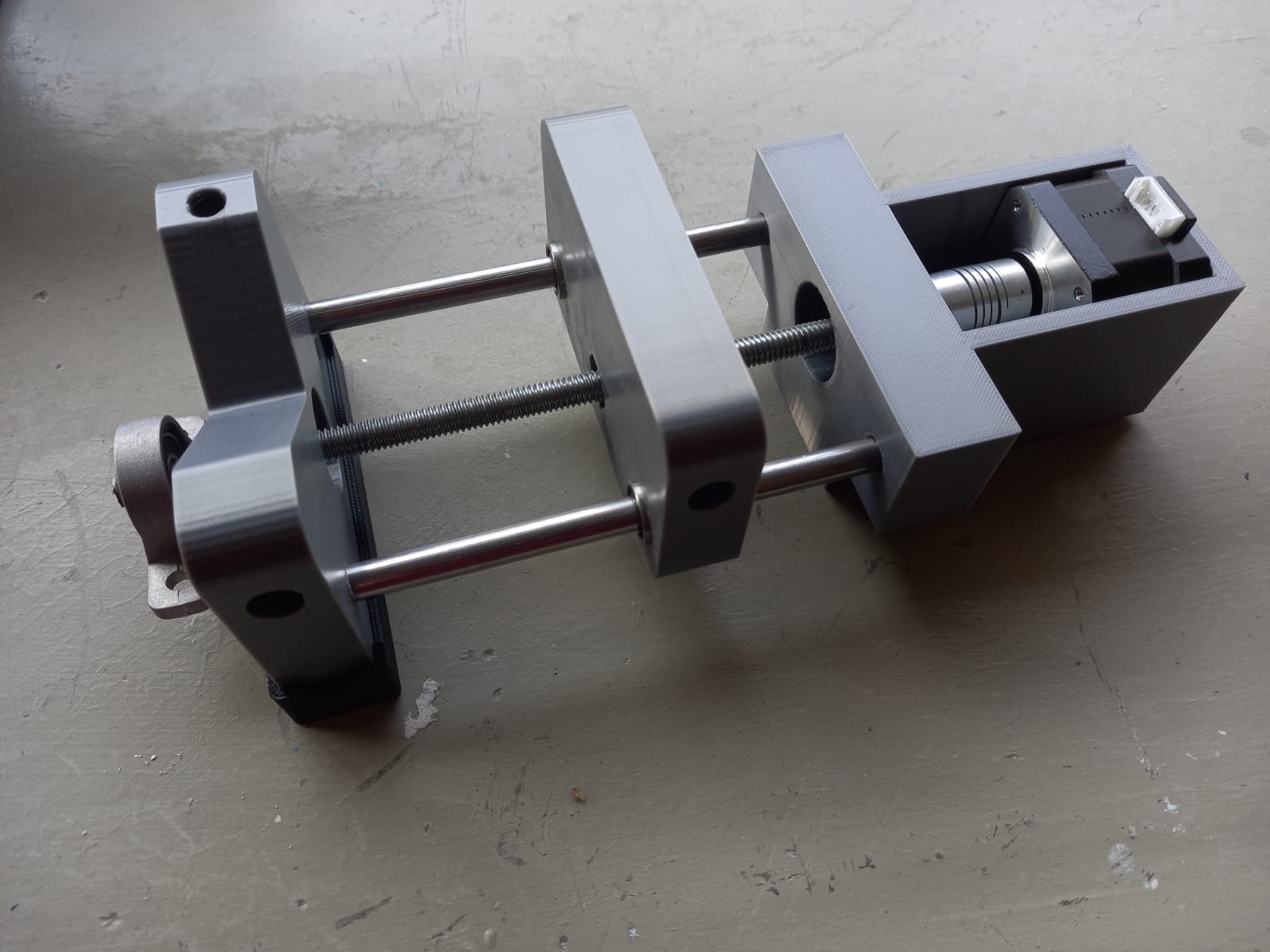
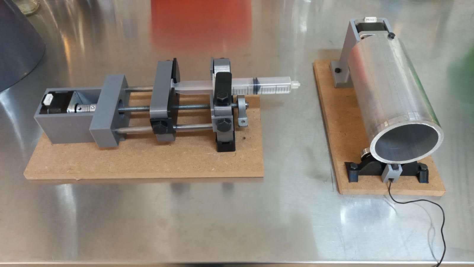
This is the prototype.
Grounded Collector Drum
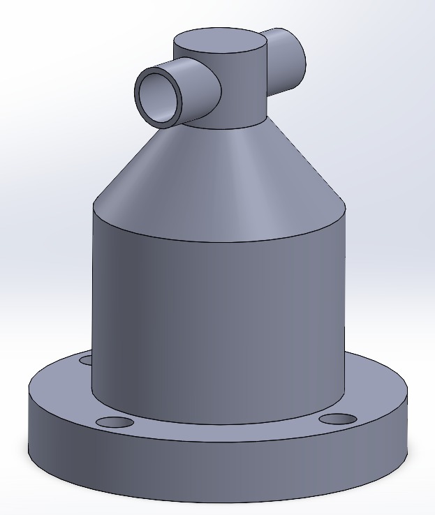
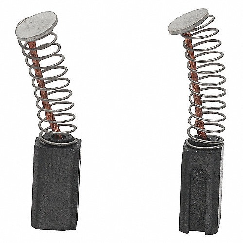
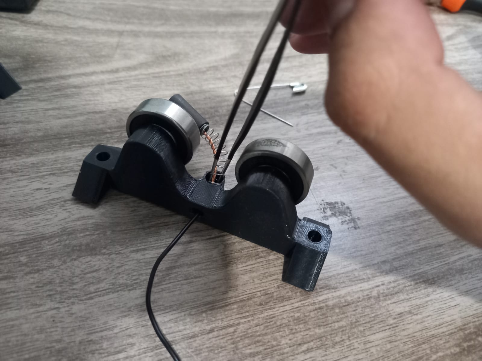
For the material collector, I preferred to use a rotating roller designed to be grounded at all times. So, I focused on this first. My advisor and I thought of using a Dremel carbon brush. These are composed of an intertwined copper wire connected to a carbon tip to apply the necessary pressure on the metal, ensuring contact for electricity flow.
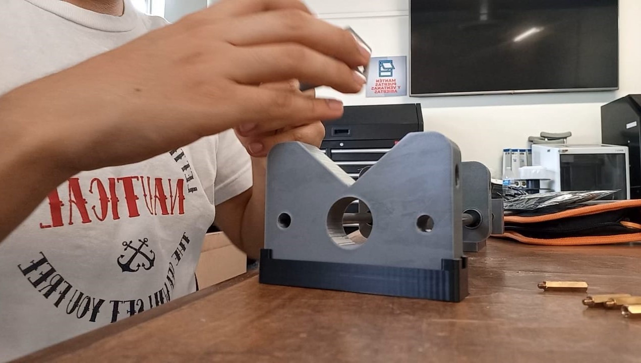
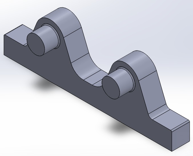
This piece is designed to have bearings in the two extruded circles to provide height and help reduce the motor's effort when rotating the roller. This way, the motor does not have to bear the roller's weight; instead, this piece does.
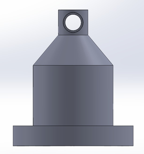
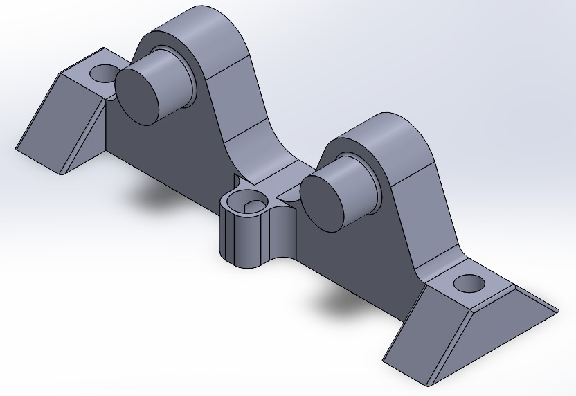
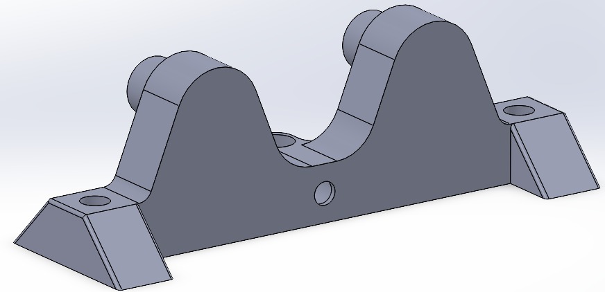
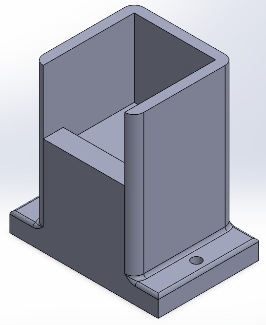
The previous design was very unstable, would fall over, and I forgot to include holes to secure it to a wooden base. This design provides stability with its trapezoidal sides. It also has a cavity to hold the motor brush.
I created this piece after testing the mechanism because the carbon brush did not consistently touch the roller, and this piece prevents it from moving out of place, ensuring it stays grounded. It's a small but very important piece.
This base will be fixed to a piece of wood to provide height and support to the motor.
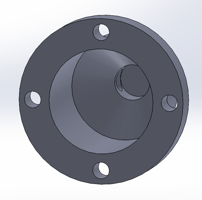
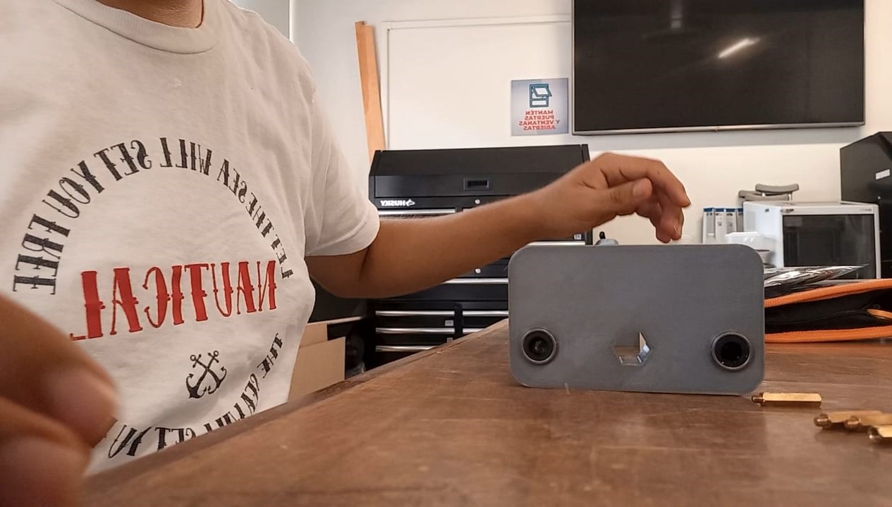
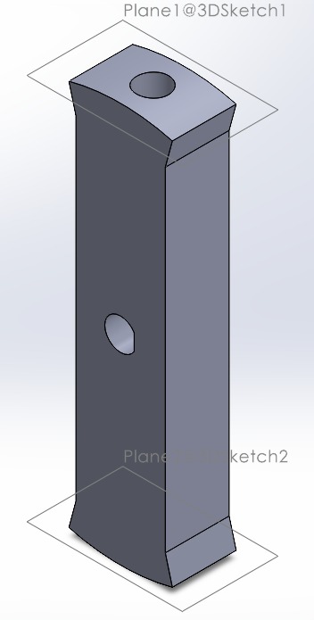
This piece is designed to fit the inner diameter of the aluminum cylinder with two holes, one at each end, to secure it to the aluminum tube. In the middle, there is a hole with an irregular shape to match the stepper motor shaft, ensuring a slight press fit.
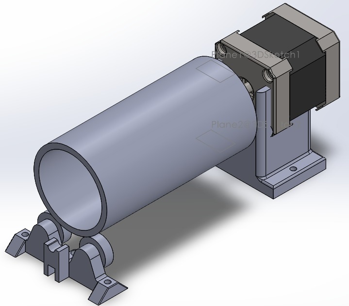
3D Model: Grounded Collector Drum
This is how the assembly of all the pieces looks in SolidWorks:
The manufacturing of this piece was as follows:
The same parameters were used for the 3D printing. However, creating this mechanism was much more complex, haha. First of all, I dressed in basic safety equipment, which includes steel-toed boots, a lab coat or overalls, and safety glasses.

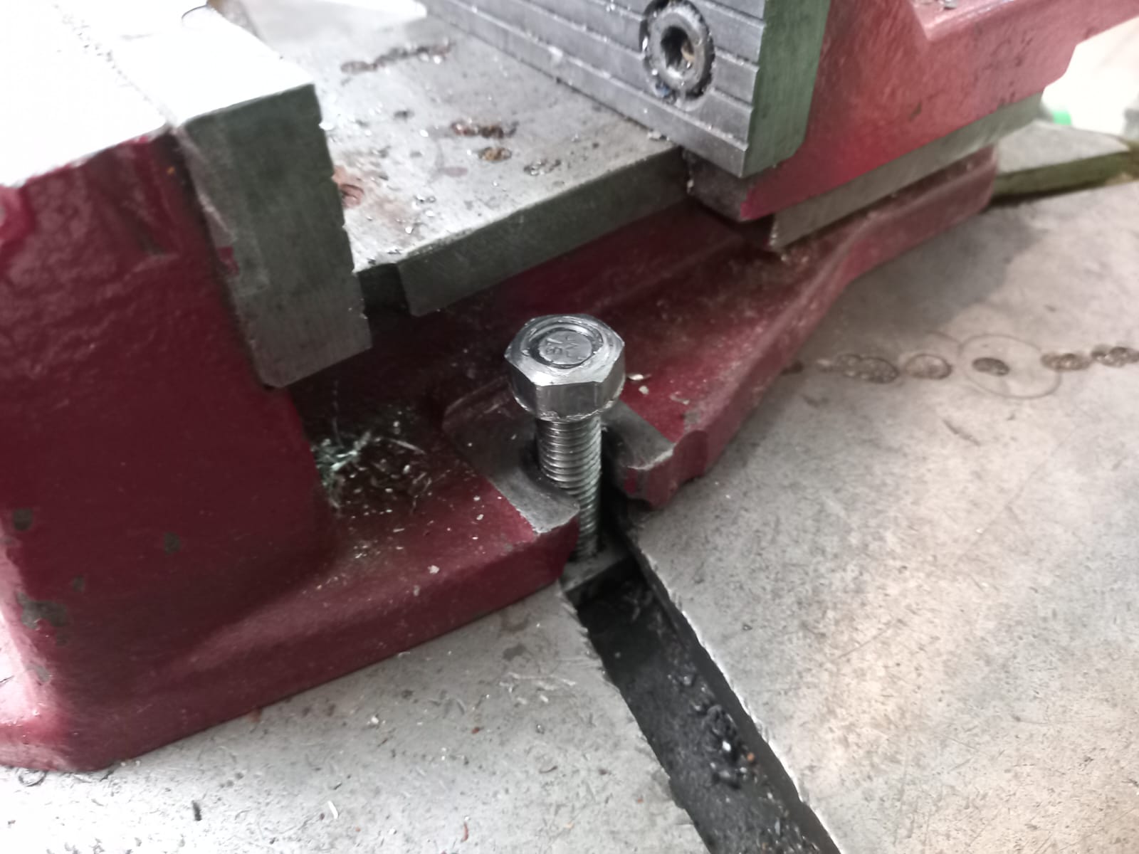
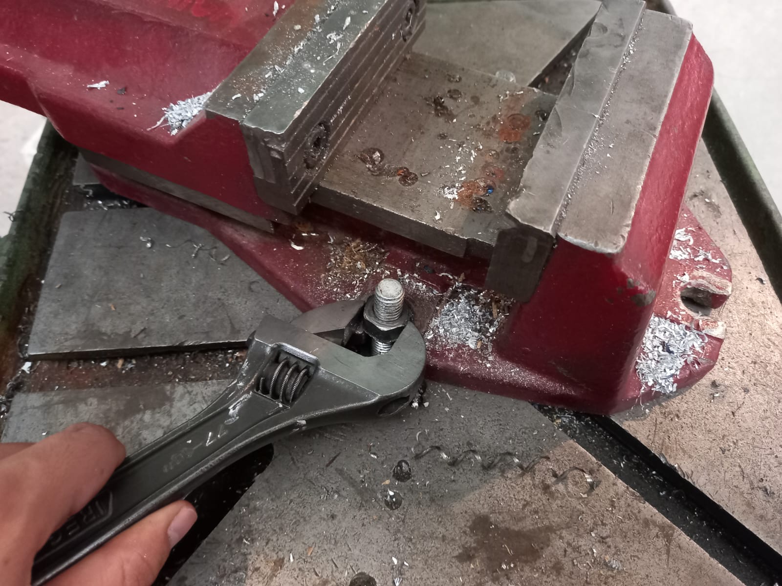
I used a vice to secure a 15 cm long aluminum cylinder with a 2 1/2 inch inner diameter. It is important to tighten the vice's clamps (screws) and jaws so that the piece doesn't fly off and cause accidents.
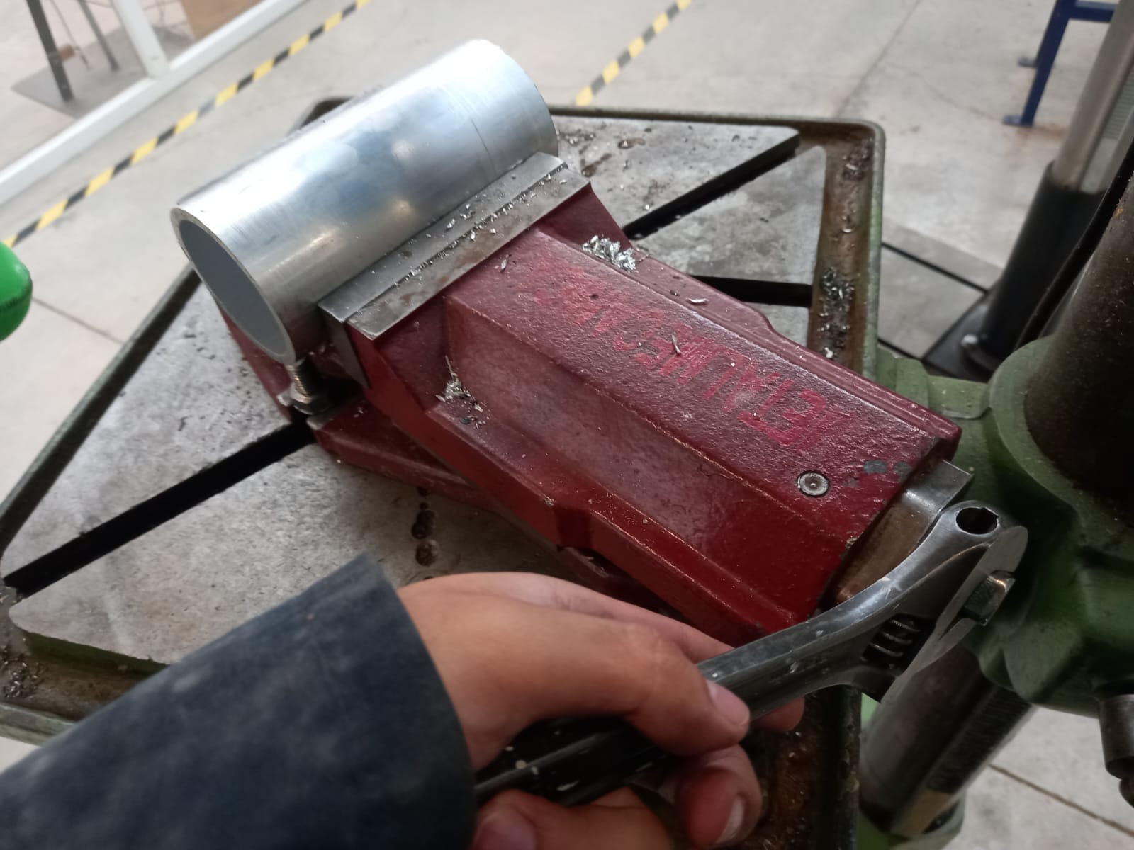
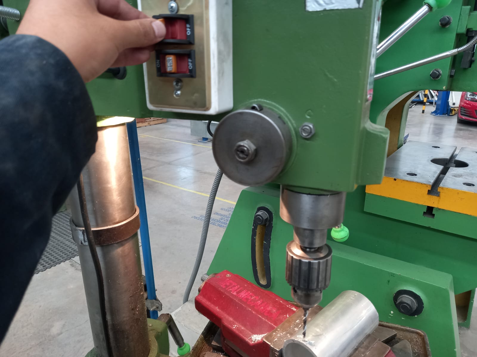
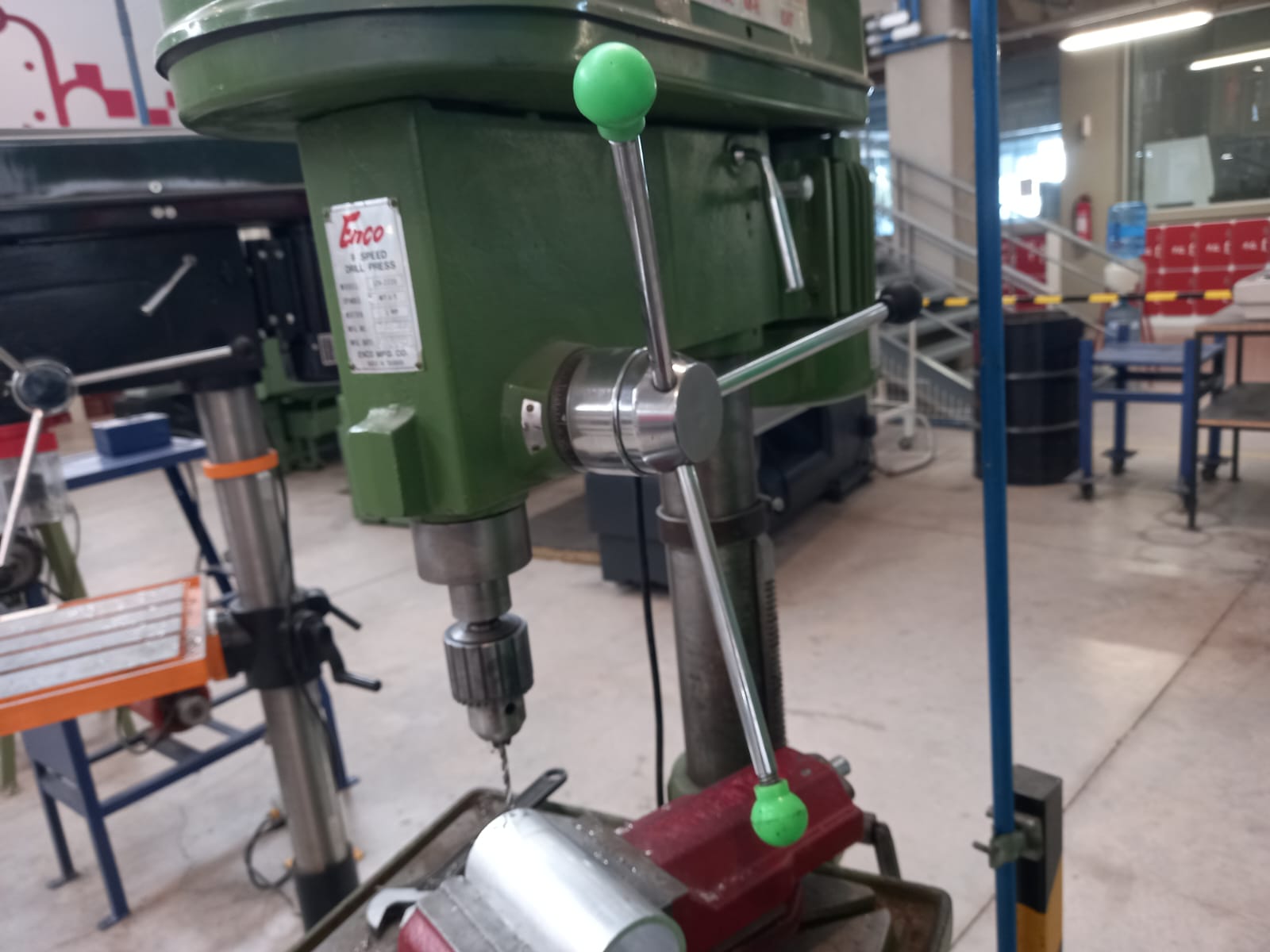
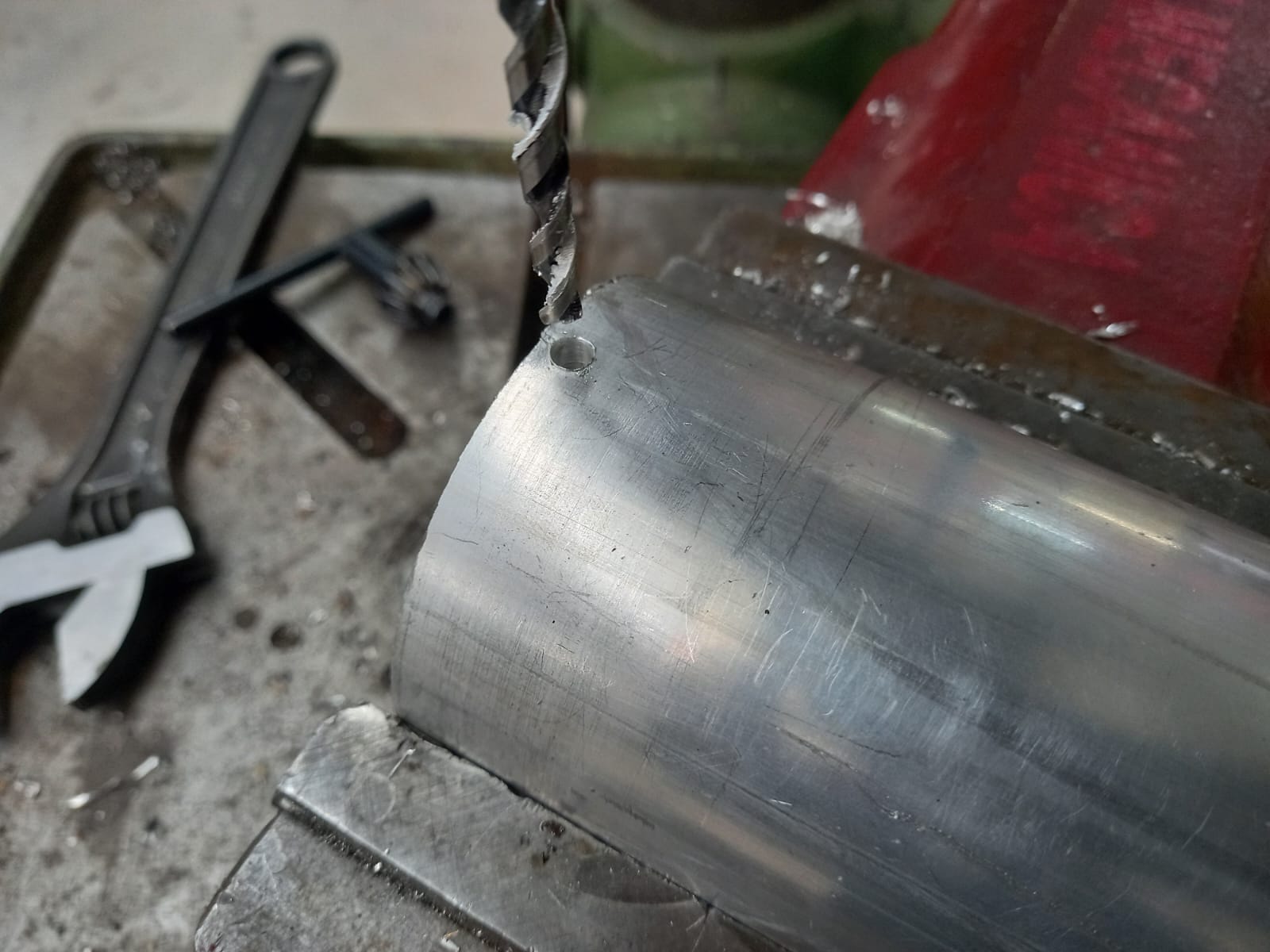
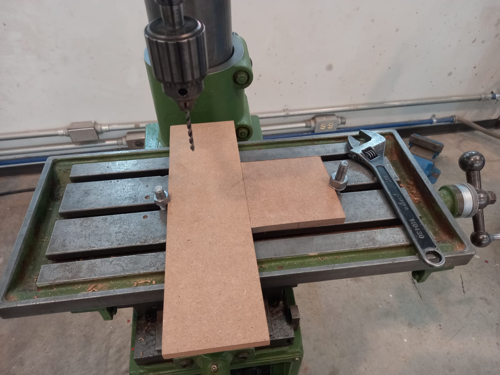
I placed the vice with the cylinder in a drill press. It is very easy to use. You secure the vice to the base of the drill press and place your piece under the chuck. Once everything is secured, meaning nothing moves, you proceed to turn on the machine with the switch and slowly pull the lever to lower the drill bit and drill. In my case, I used a 5 mm diameter drill bit.
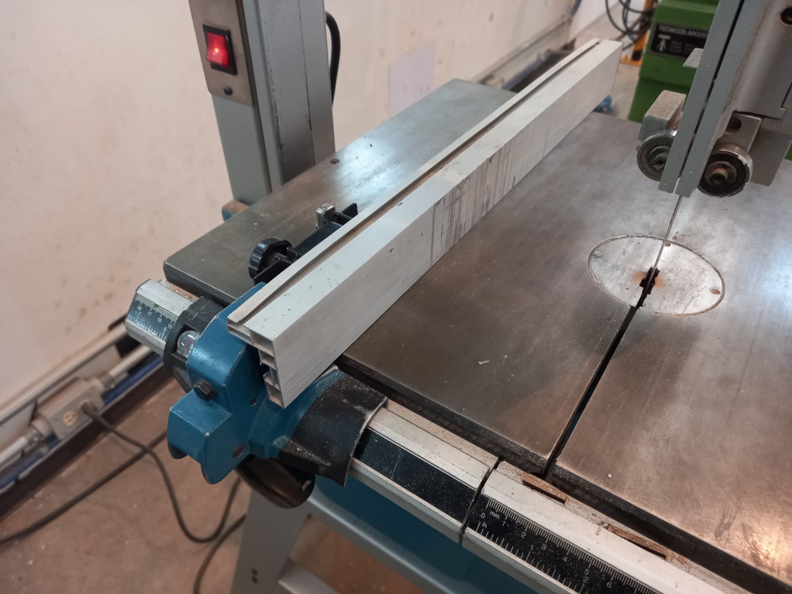
Next, I used a bandsaw to cut scrap MDF with a thickness of 15 mm to fix the mechanism parts. There were two rectangles of **** for the syringe pump and **** for the collector. Beside the machine is the switch to turn it on.
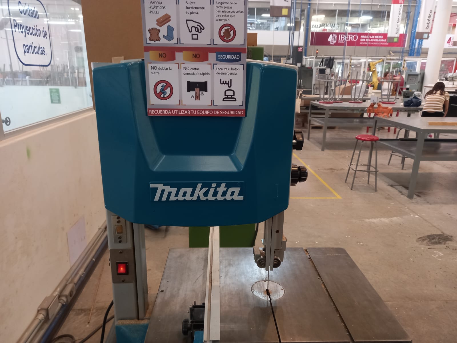
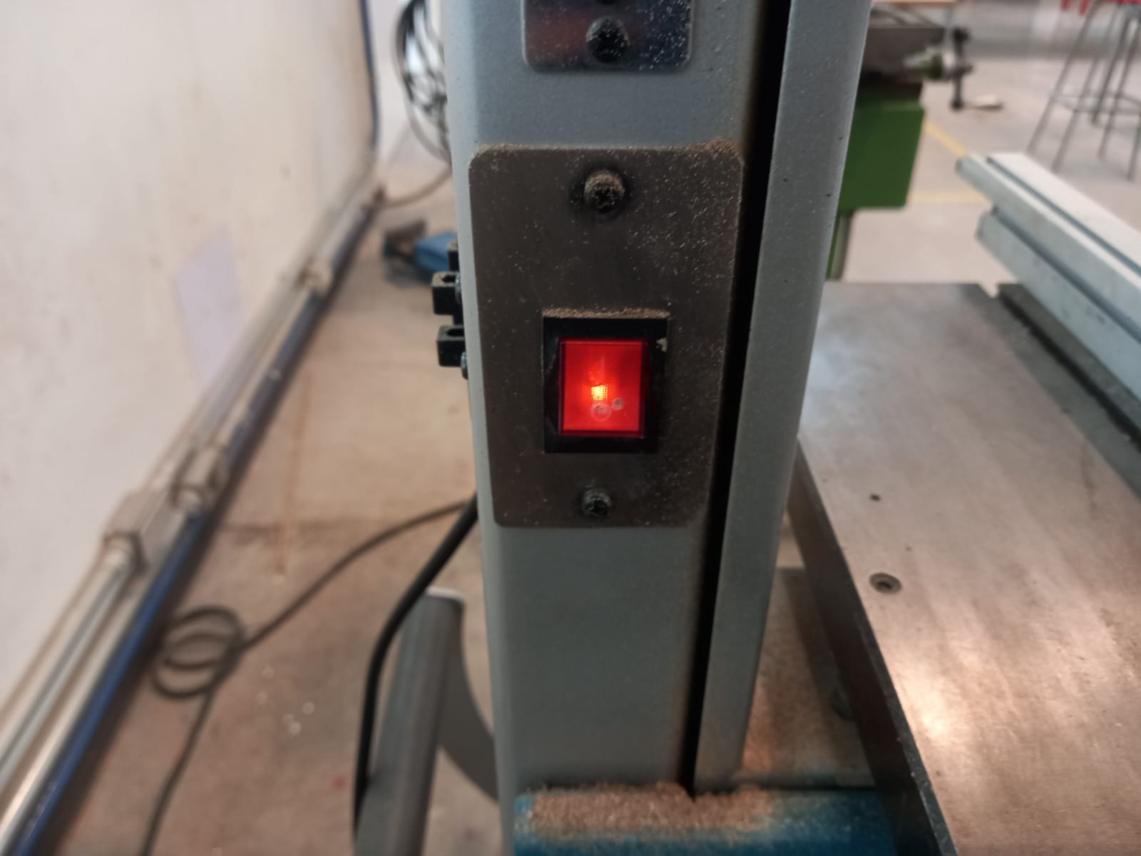
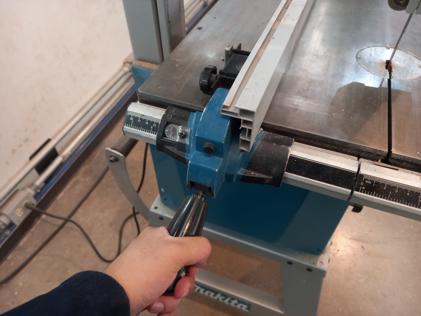
And on top is the rule to make a straight cut. It is secured with a clamp underneath; up to move, down to fix. Very simple.
I also used a wood drill press with the same 5 mm drill bit to drill the holes where the screws would go to fix the mechanism parts. However, I assembled a sacrificial bed by securing it with screws, washers, and MDF pieces to prevent the drill bit from breaking.
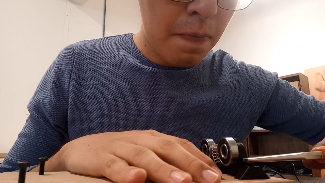
Finally, I soldered a cable to the carbon for the Dremel, which will go to the high voltage power supply. Likewise, I pressed the bearings into the piece where the aluminum cylinder will rest, and the carbon for the Dremel with pliers inside the cavity of the piece.
Testing conductivity
High-voltage power supply
For the high voltage power supply, I bought a soldering kit on Amazon that promises to deliver around 15 kV. I followed the step-by-step instructions from a YouTube video. However, here are the most important points:
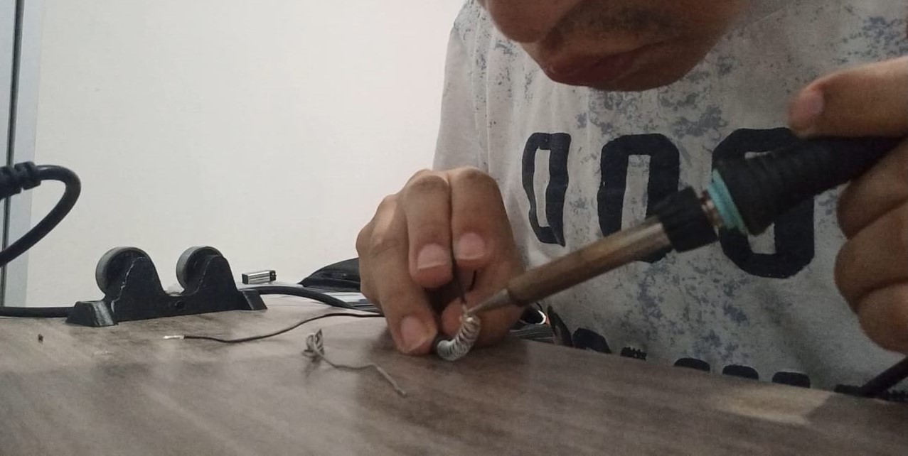
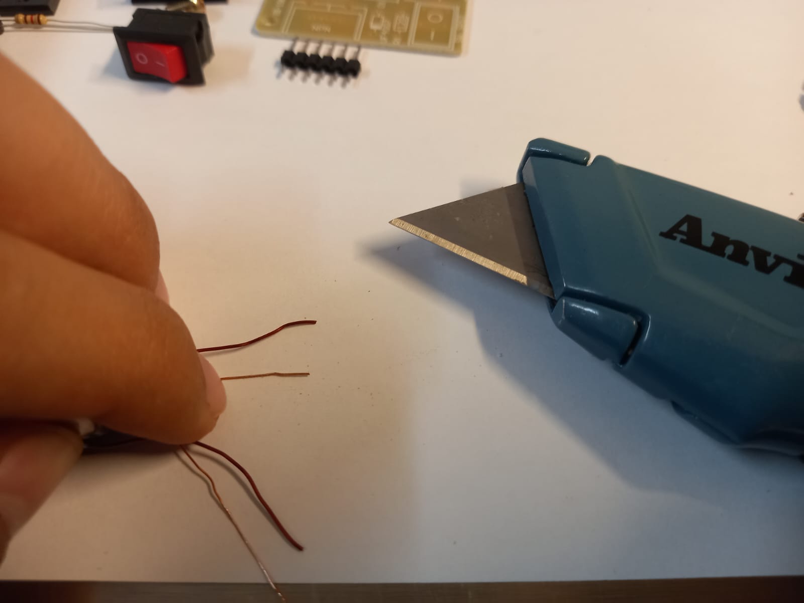
- Removing the enamel from the copper wires is essential to ensure they make contact; otherwise, it will not work.
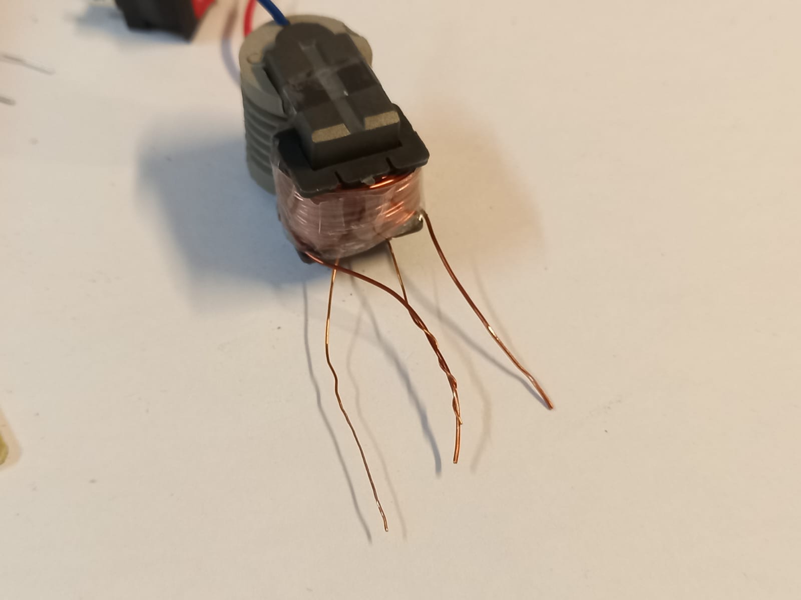
- This is how the core should look. It has 4 wires, but the first one on the left goes with the third, which is slightly thinner, to power the primary coil.
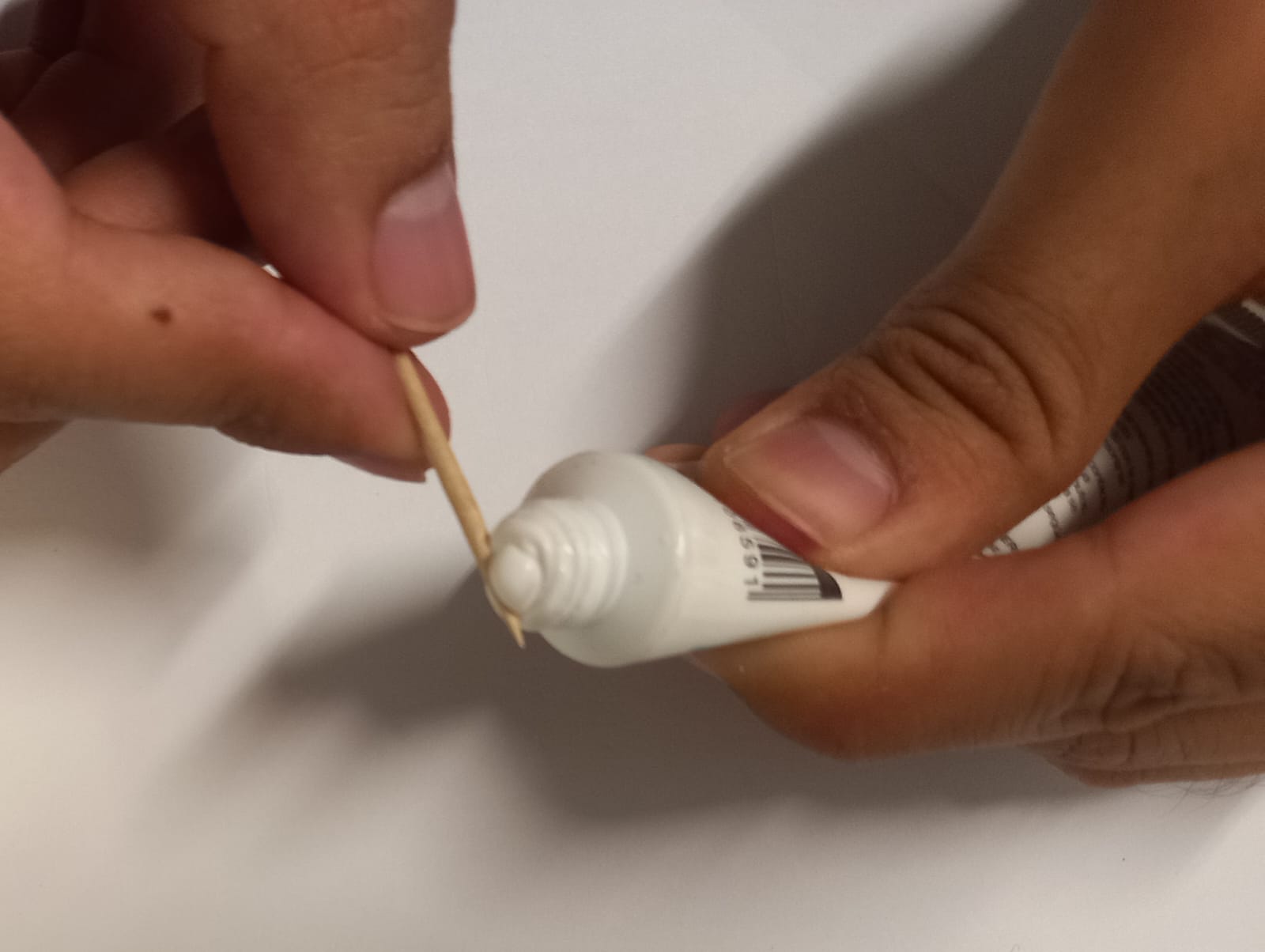
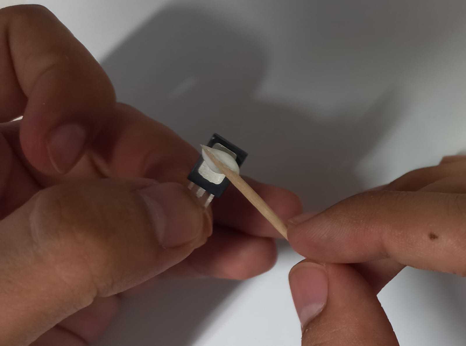
- Using thermal paste or grease is recommended for the transistor; it will help prolong the use and life of the circuit. Finally, secure the transistor to the heatsink with a screw.
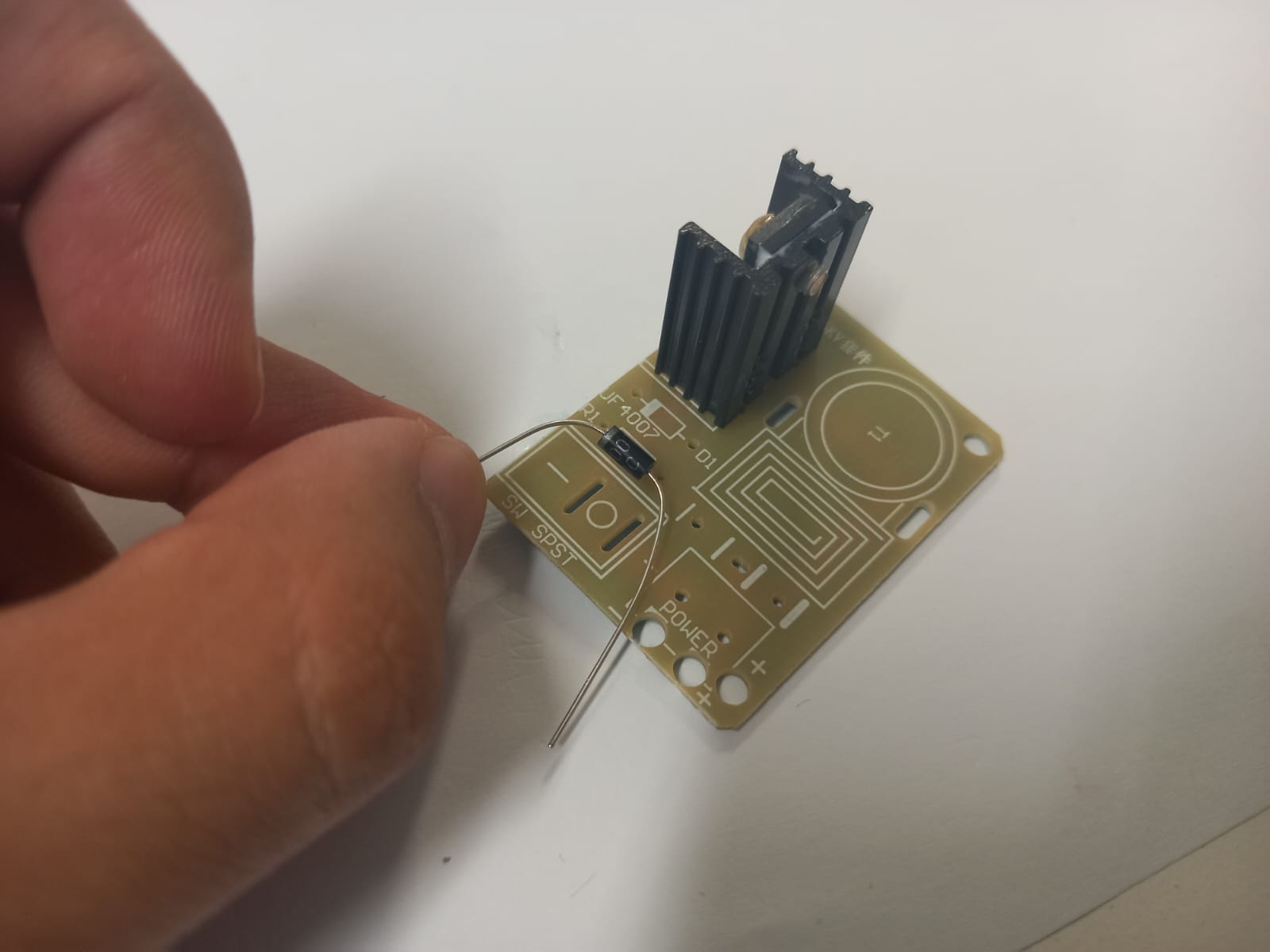
- Apart from that, the board is very instructive, indicating the position and location of each component.
POOWEEEER!
Programming
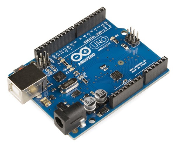
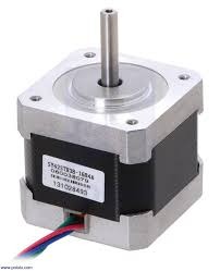
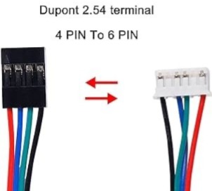
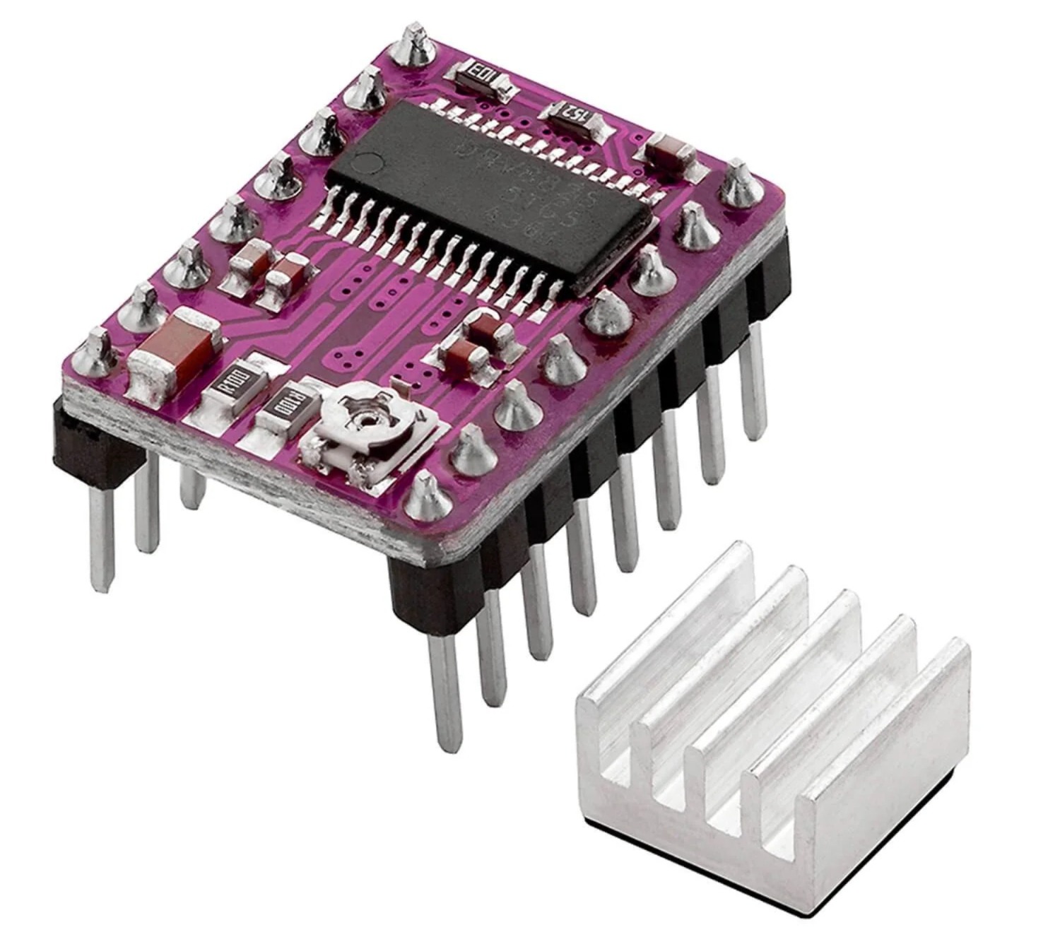
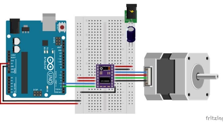
I first conducted tests with an Arduino UNO board, Nema 17 motors, Dupont cables, and the DRV8825 stepper motor driver.
IMPORTANT:
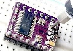
Initially, none of the motors worked, and when they did, they moved too fast without the possibility of reducing their speed through the programming code. After studying the driver further, I realized I had not correctly adjusted its potentiometer. Using a screwdriver, I gradually turned it until the motor moved smoothly and made minimal noise.
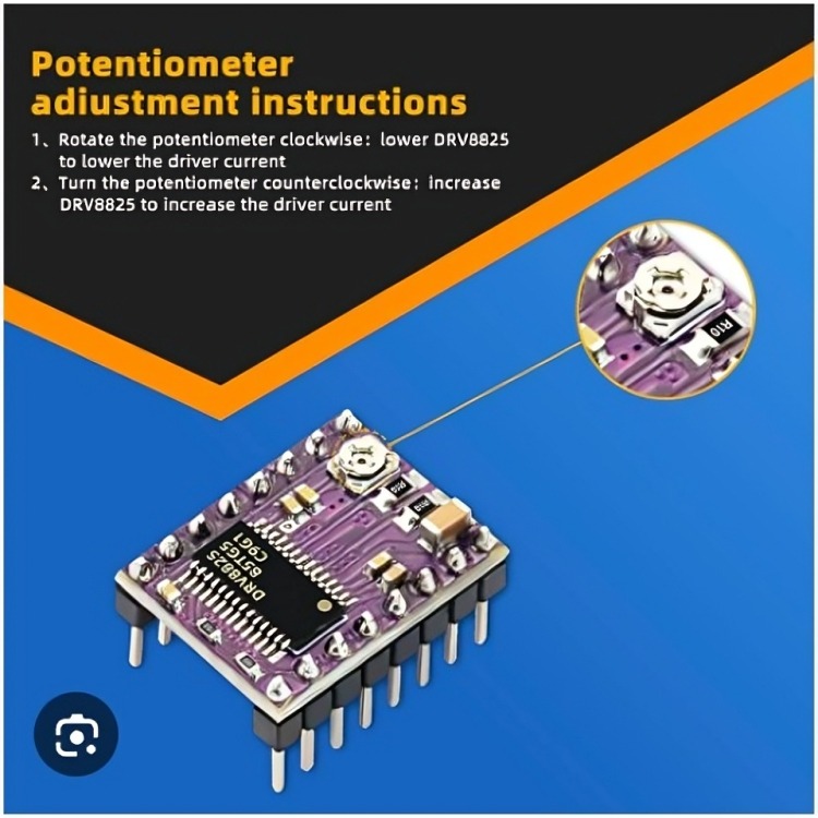
CAUTION:
Turning the potentiometer forcefully or quickly can break it and damage the circuit, as I experienced.
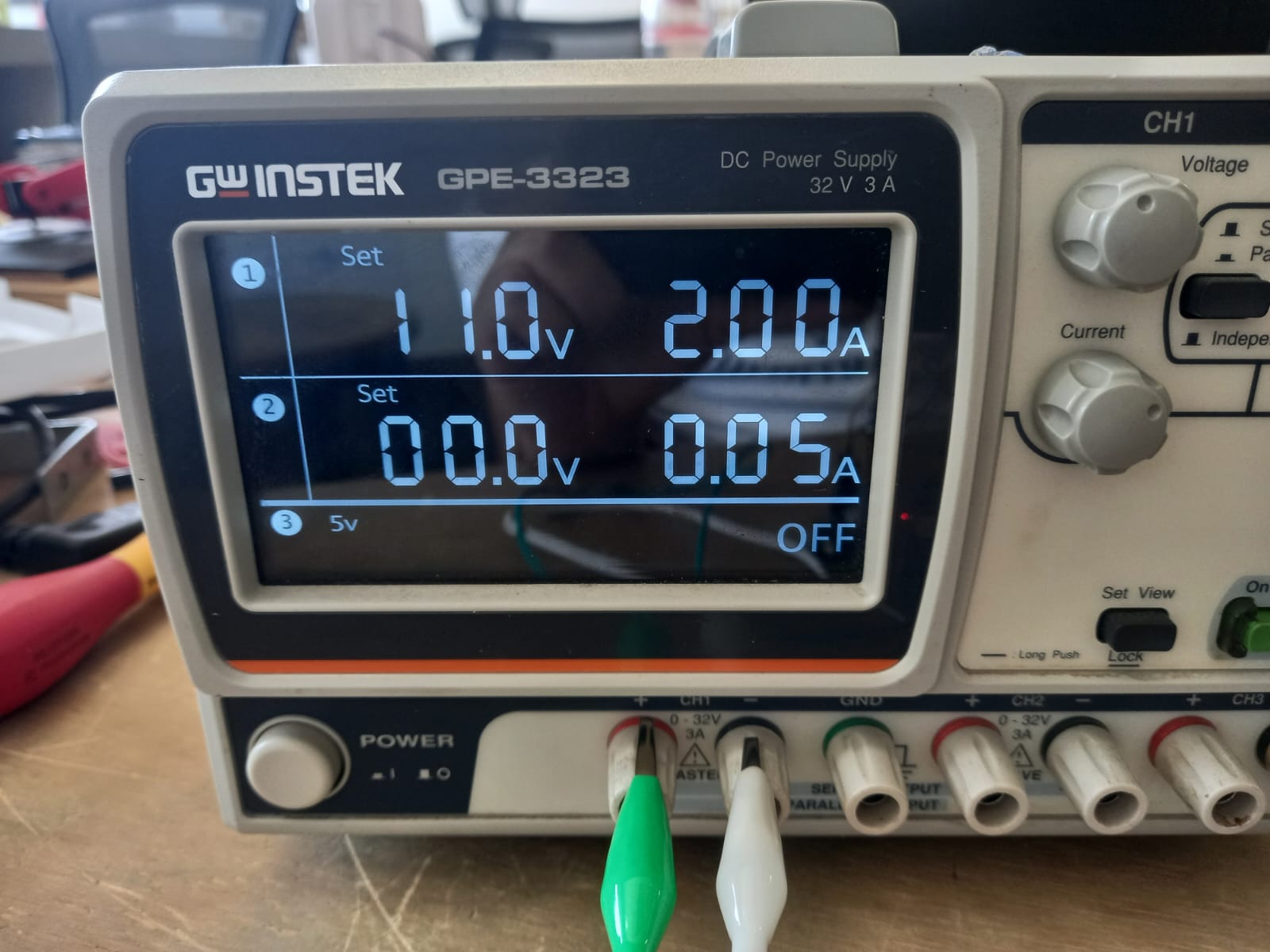
This page (Click here) was very helpful for testing the motors and includes more examples on using a stepper motor. Below is the diagram I followed and the code I used for testing them. I set the power supply to 11 volts and 2 amperes to test the motors, and they worked very well.
After learning how a stepper motor works, I tested both motors in their mechanisms to confirm everything functioned as simulated and expected. Fortunately, everything worked perfectly.
Syringe pump
Grounded Collector Drum
With the help of Oliver, a FAB LAB instructor, we made corrections to the code using the AccelStepper library to easily control the speed and steps of the motors. Once satisfied with the speed, I decided to add three buttons to interact with the machine. The first button returns the system to Home, moving the sliding piece toward the motor to insert a new filled syringe. The second button starts the mechanism at the speed set in the code, and the third button stops and resumes the machine.
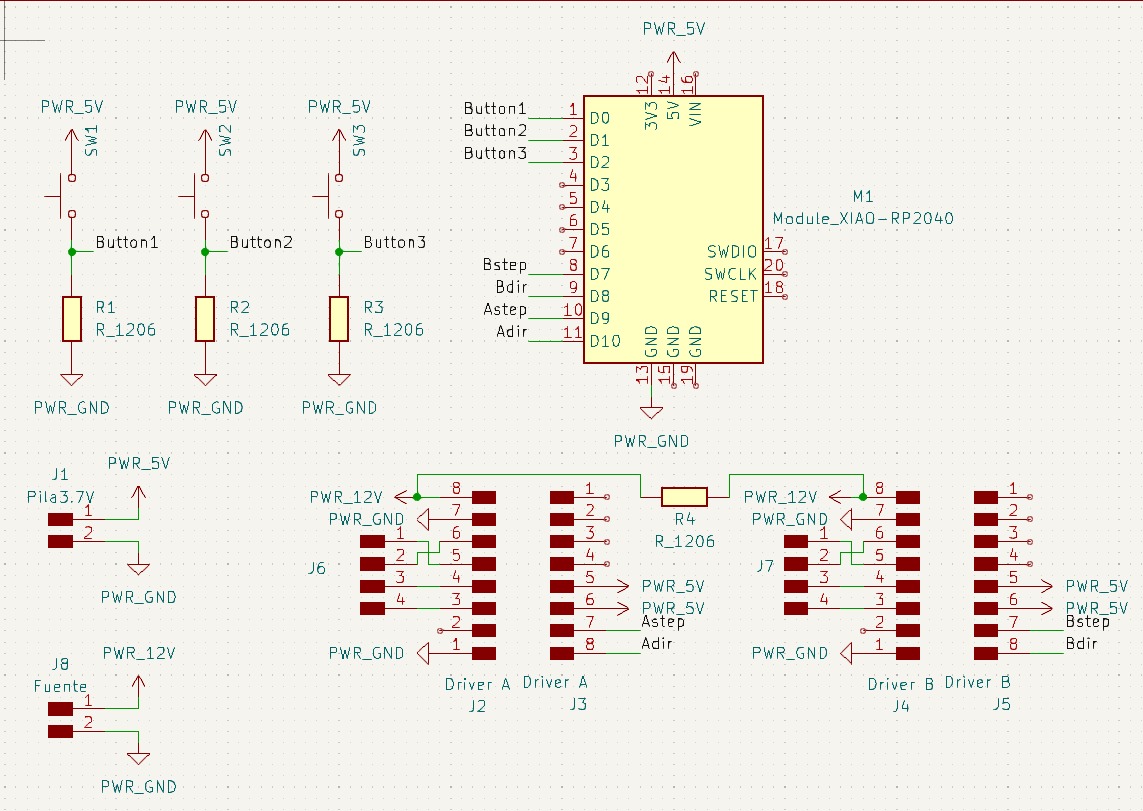
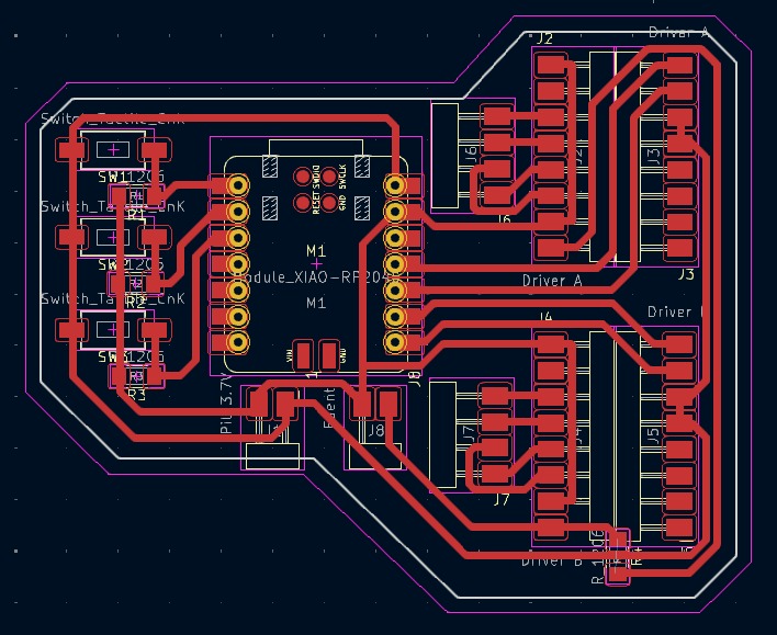
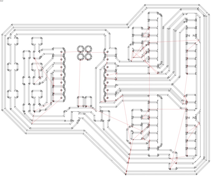
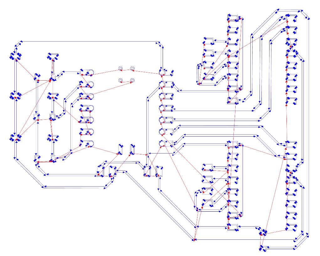
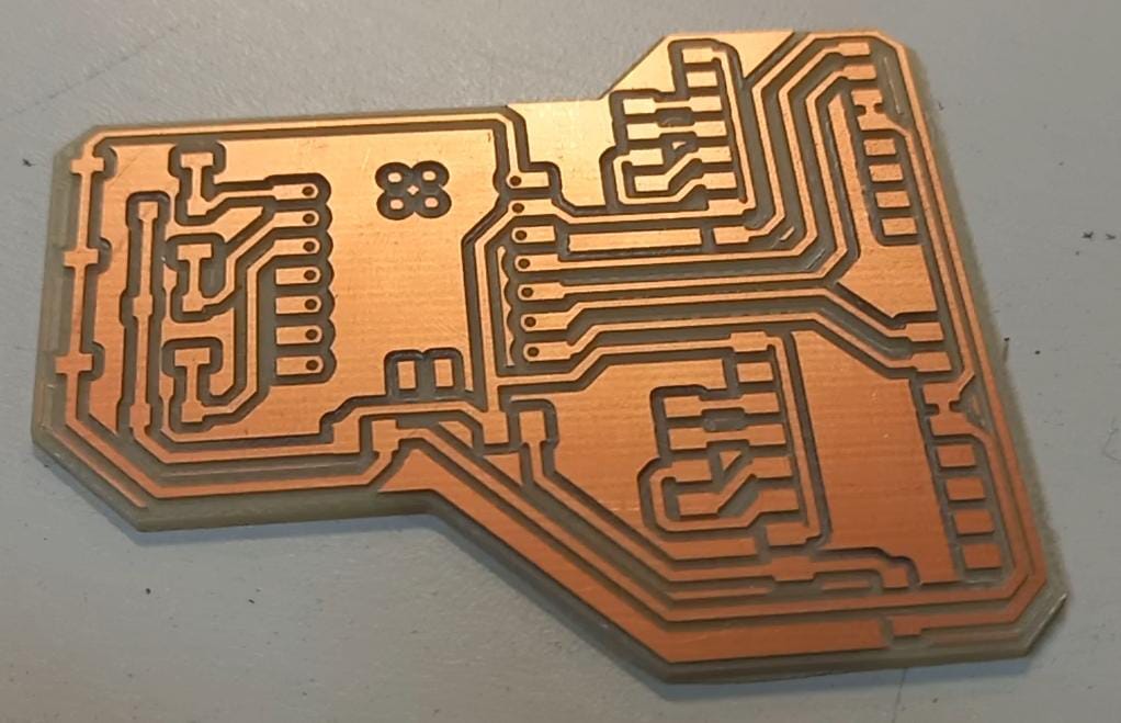
After testing with the Arduino board, I decided to try and connect it to a XIAO RP2040, which I would use in my project. The code compiled well and worked correctly. So, I designed the PCB in KiCad.

IMPORTANT:
- Don't forget to invert your .svg file in MODS. If it seems like this is incorrect.
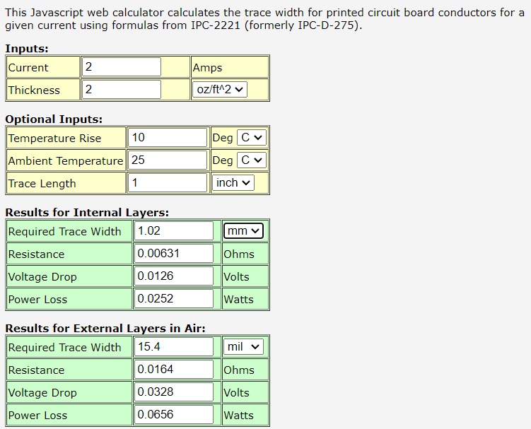
- If you want more power on your motors. So, calculate the traces width here (Click).
- Because I burned my drivers, I want to solder female pins to easily replace the drivers if it happens again. Therefore, I added pins to the schematic and PCB design. I measured the distance between the driver's pins with a vernier to ensure they fit the female pins. Additionally, you can add the driver's footprint to verify if the measurements are correct.
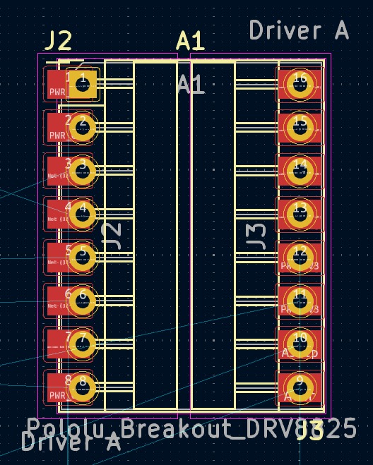
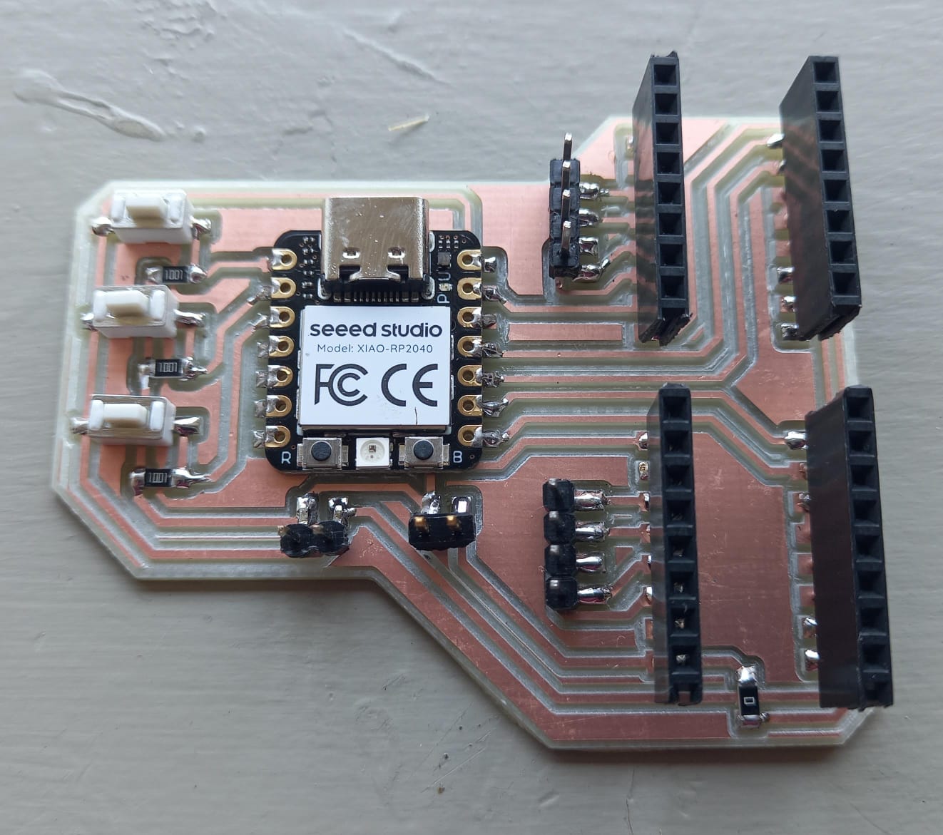
For this board, I used the following:
- XIAO RP2040
- 3 push buttons
- 3 resistors (1000 ohms)
- 1 resistor (0 ohms)
- 32 female headers to insert the motor drivers
- 12 male headers to insert the motor cables
This is my board.
Polymer
I used many formulations:
- PVA + water
- Expanded polystyrene + thinner
- Latex + water + acetone
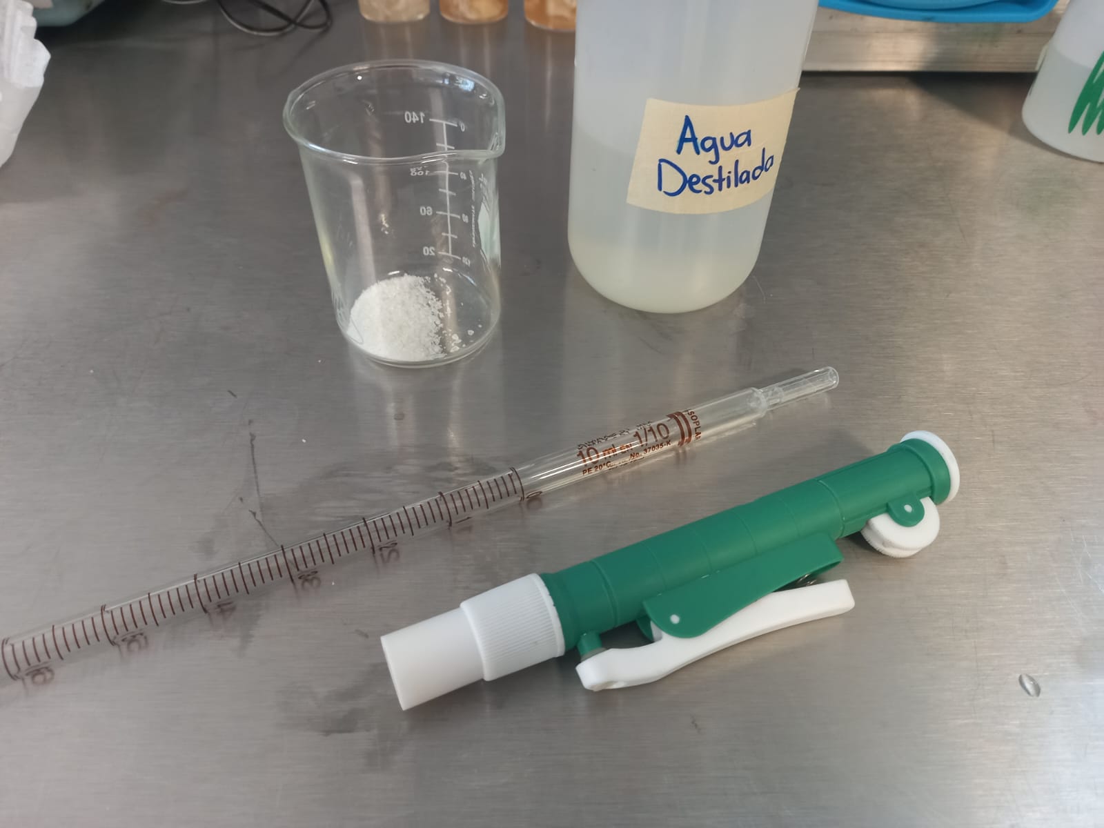
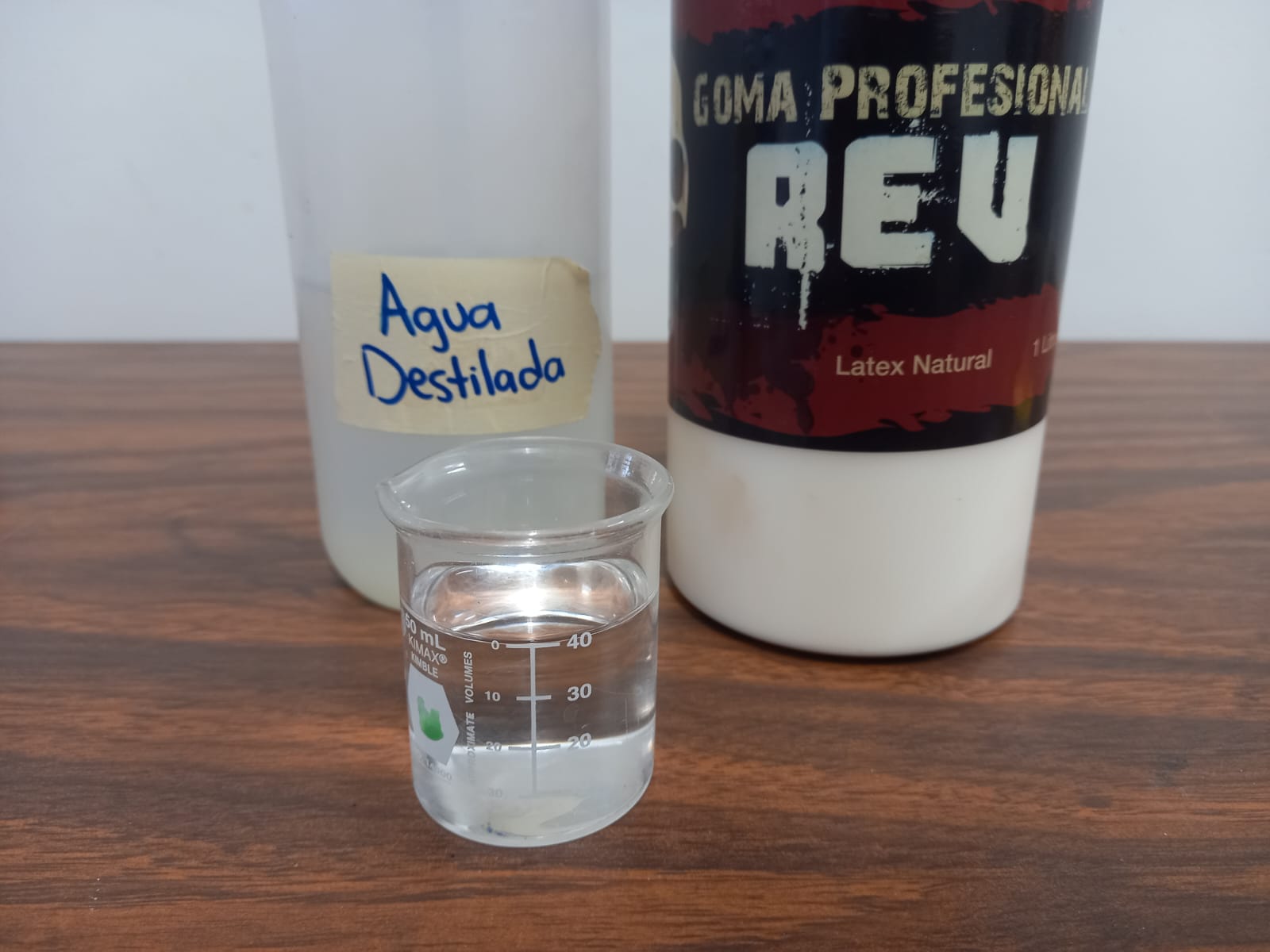
All at concentrations of 10% polymer and 90% solvent. However, I obtained results with the second formulation. Yes, from expanded polystyrene and thinner. For this, I used the following materials:
- Thinner
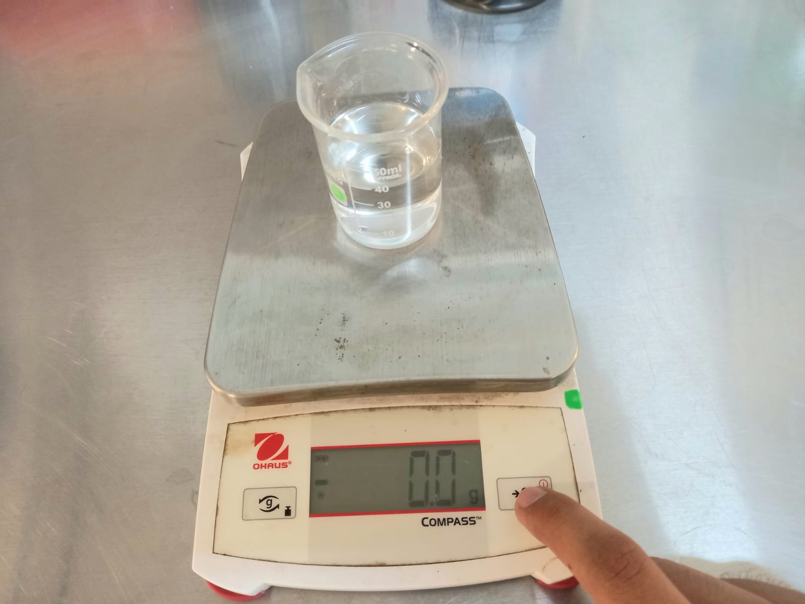
- Precision scale
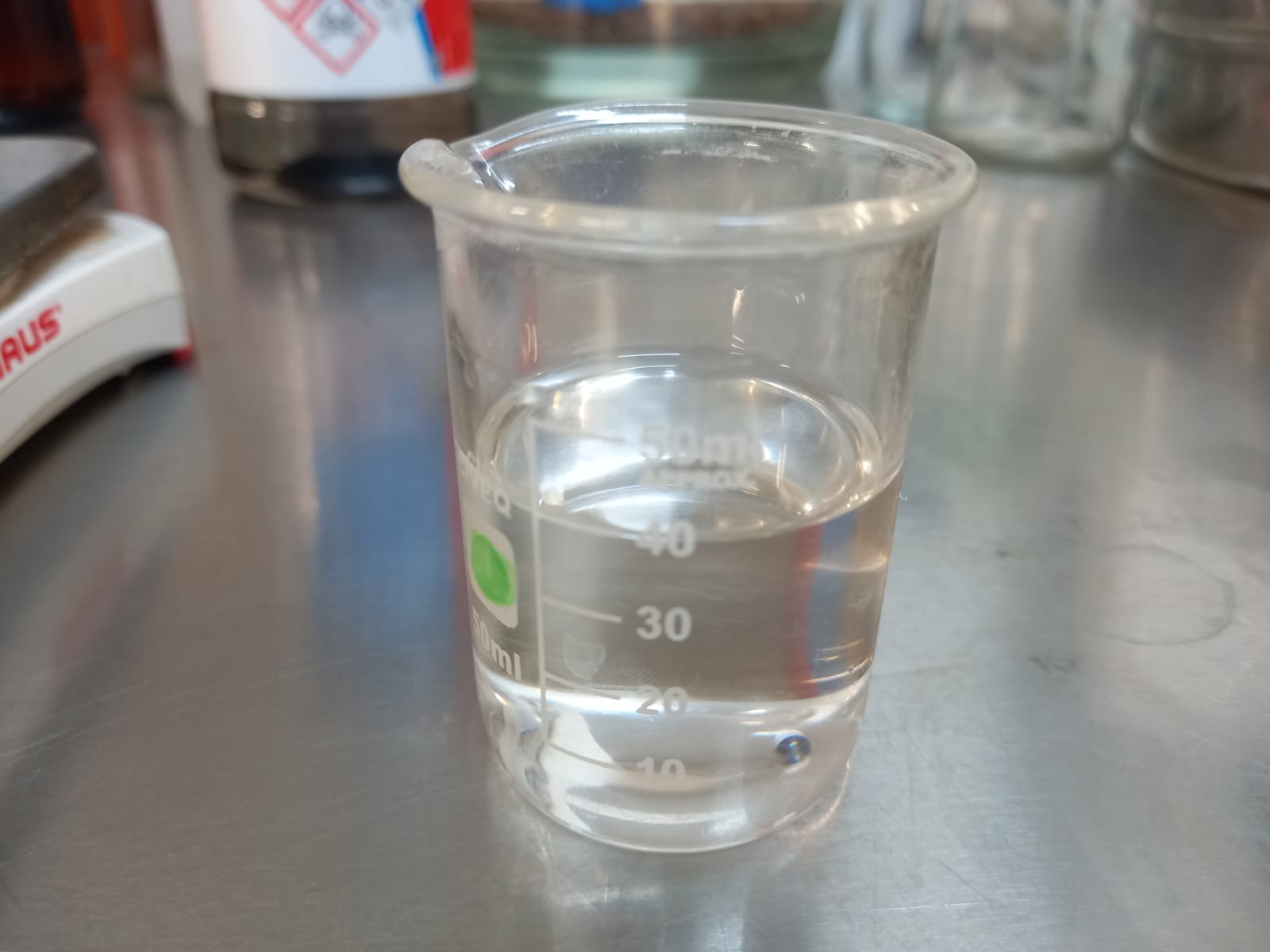
- Beaker
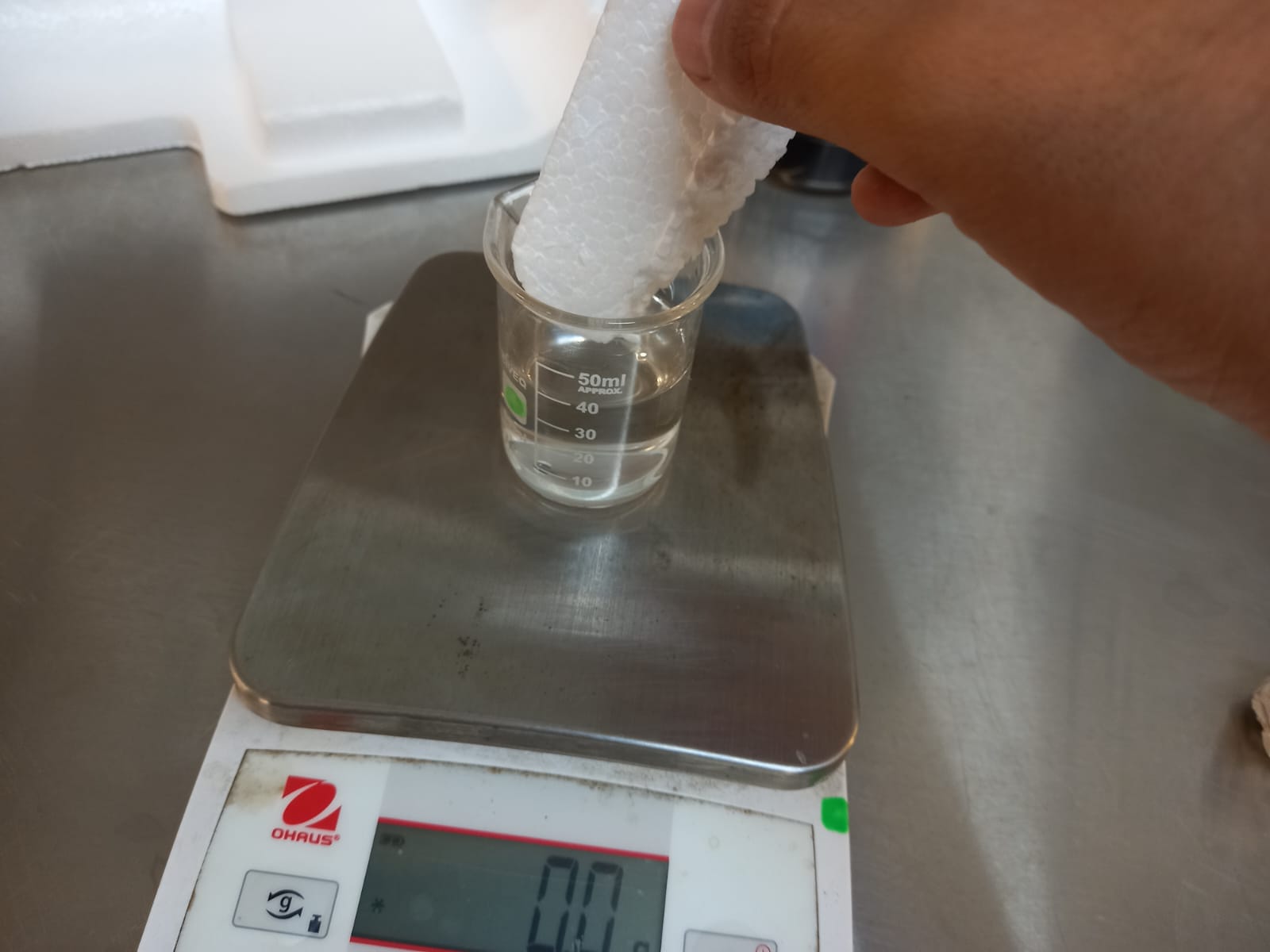
- Expanded polystyrene
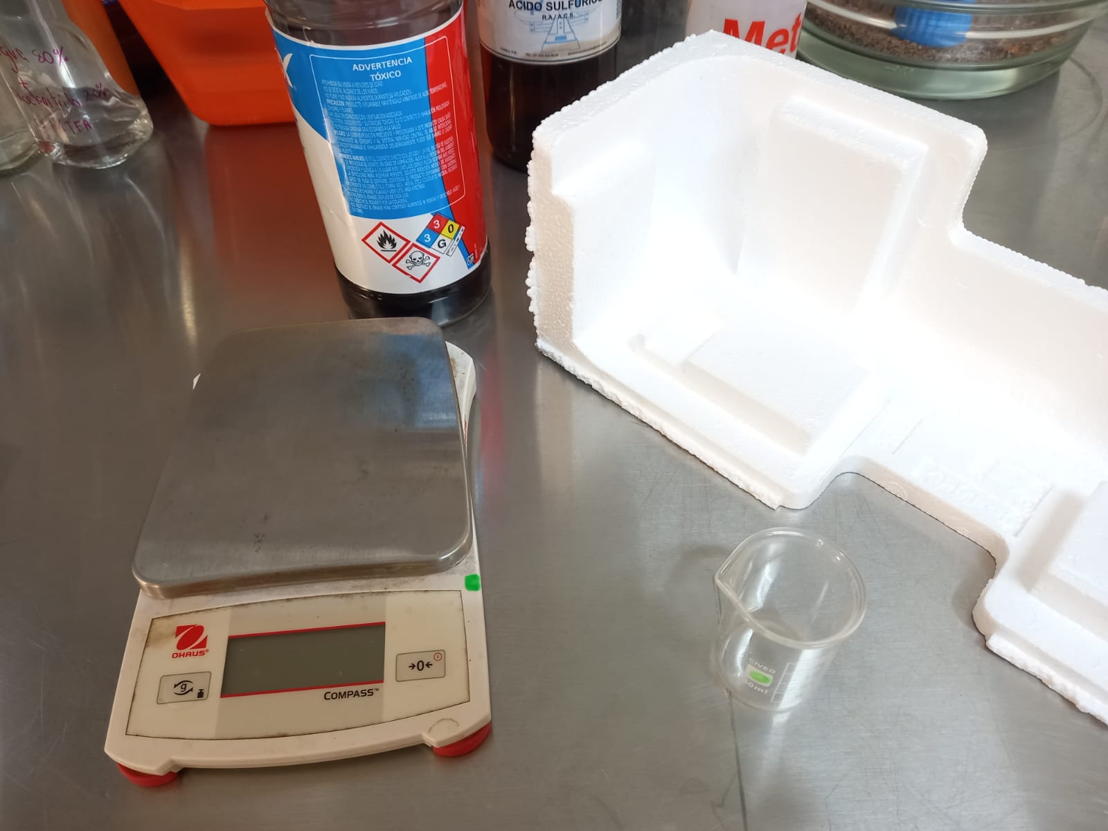
- Add 40 ml of thinner to the beaker.
- Tare the precision scale. Don't forget.
- Gradually add Expanded polystyrene.
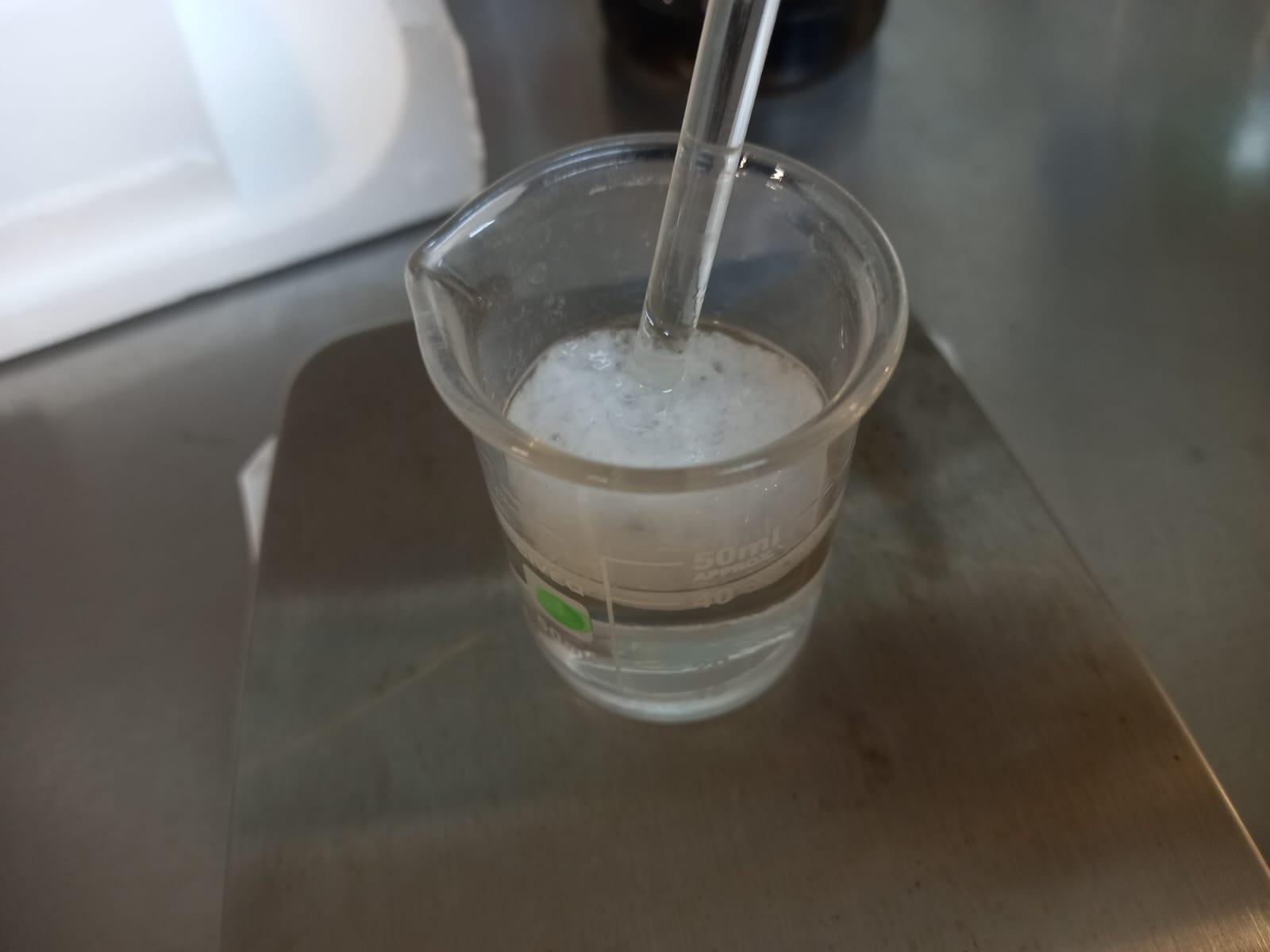
- I recommend stirring to make the mixture more homogeneous.
- Fill the beaker until it reaches 15 grams.
- Add another 100 ml of thinner.
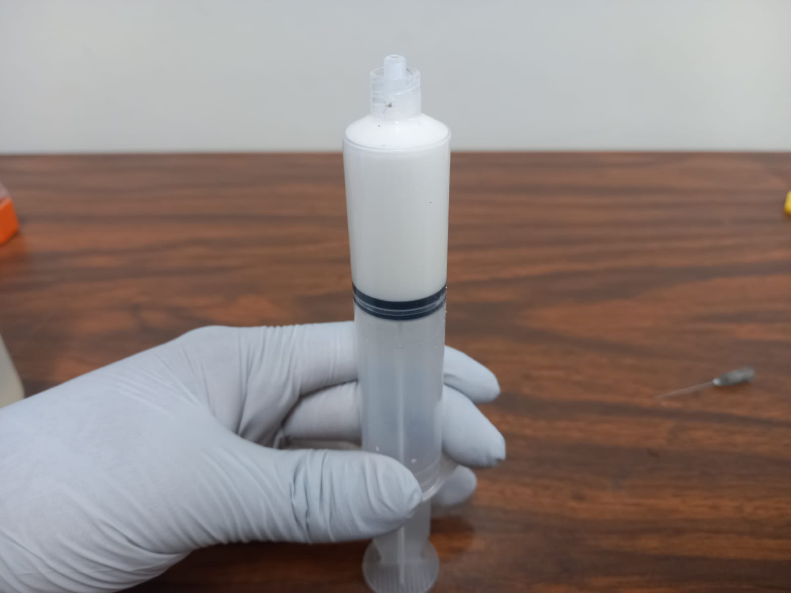
- Fill the syringe with the polymer!
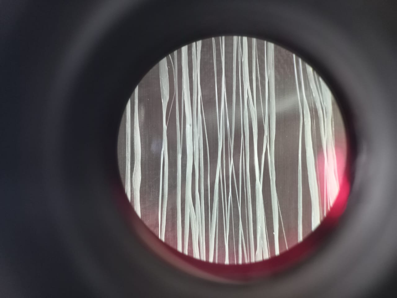
For this, connect the positive pole to the syringe needle and the negative pole to the collector roller. Turn on the power supply and let the magic happen. Here is the video and photo of its operation.
IT WOOOOORKS!!!!
Observation
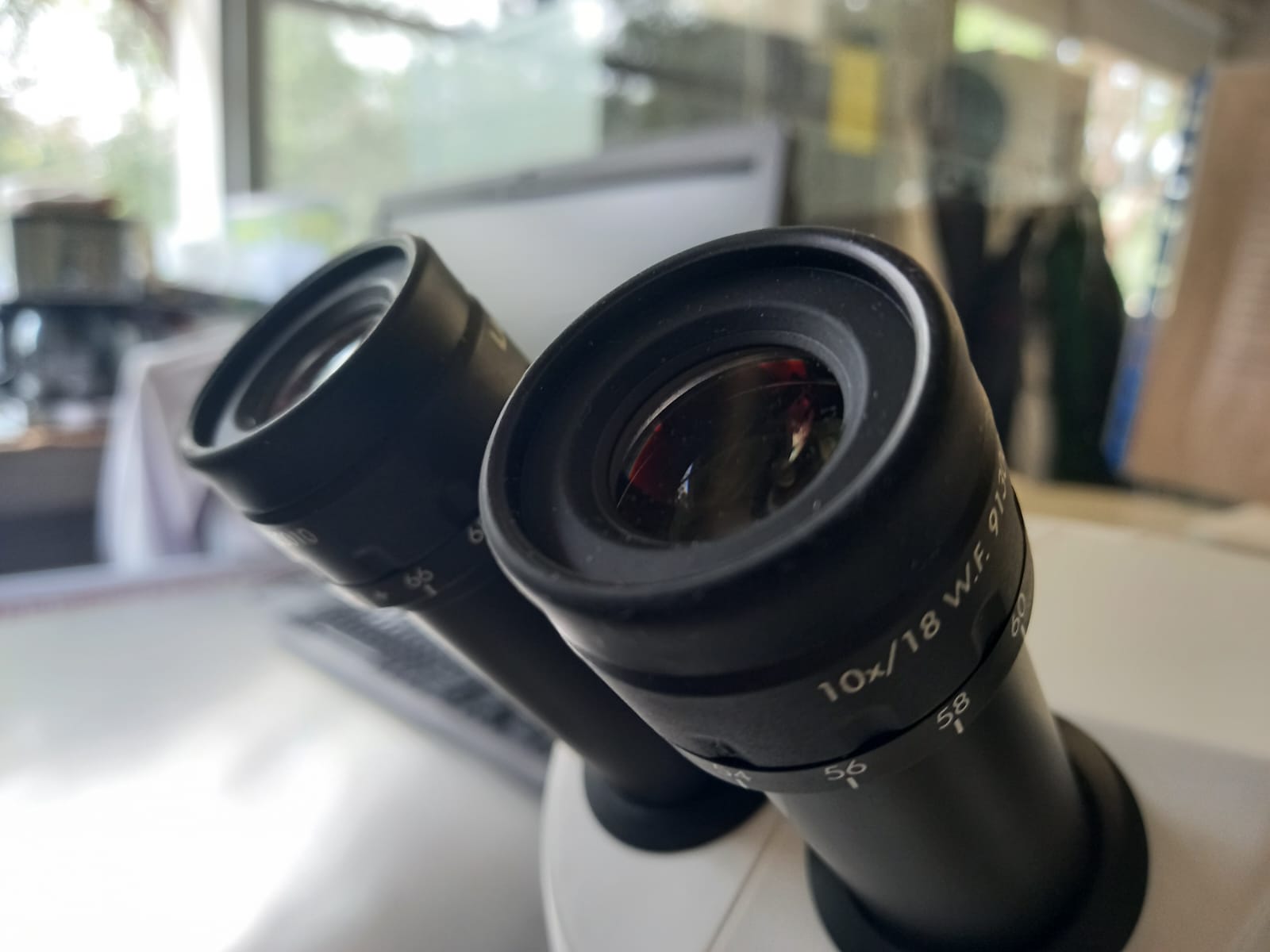
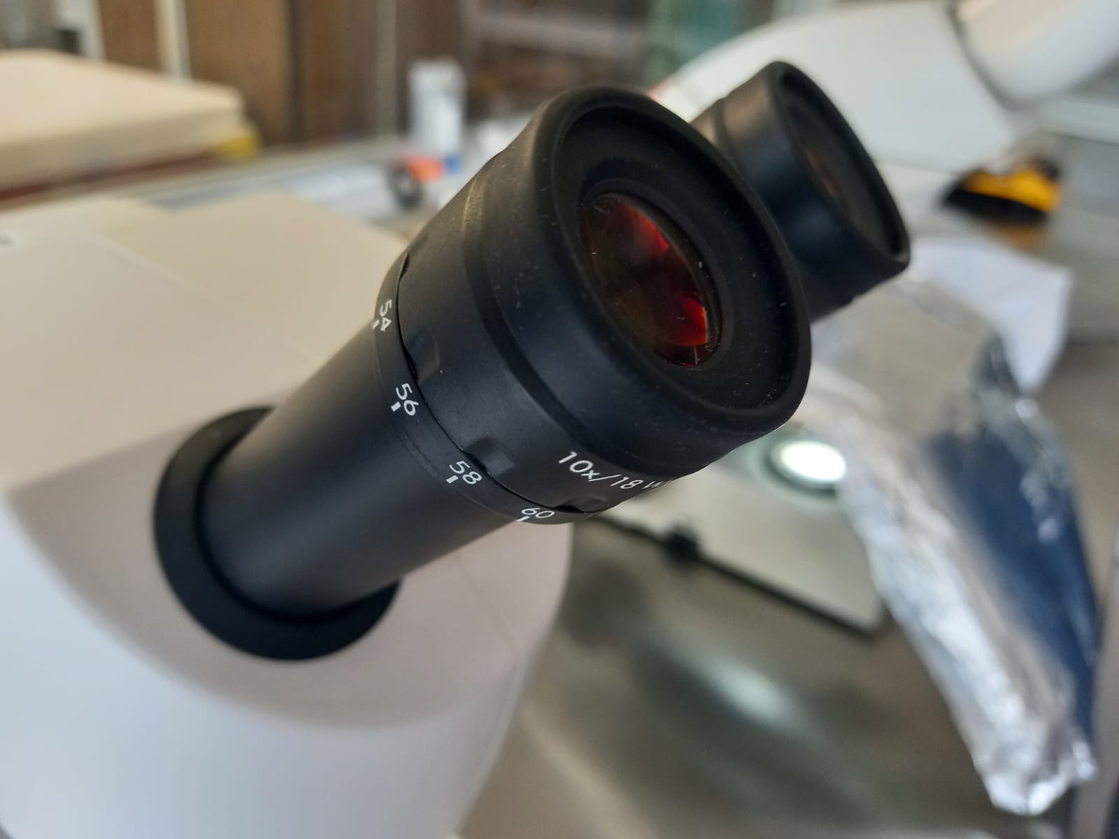
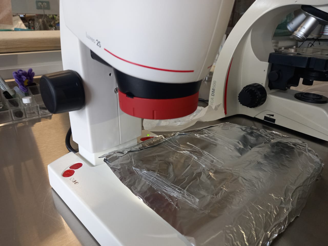
Neil, during the final project review, requested microscope photos because you must pay close attention to the thin thread in the video to notice that it works. So, I used a stereoscope of brand LABOMED model Luxeo 2S. Using it is super easy; you connect it to the domestic power supply and turn it on with the button on its side.
The objectives of this stereoscope allow viewing microns (x10), so you adjust the image resolution with the knobs.
With the side knob, you lower the head to bring the objective closer to the sample. Place the sample, I used aluminum foil for contrast, and voila, we have thread!
Packaging
Now, I chose a 3.7V 800mA battery to power the circuit and also purchased its charger.
We will solder the wires to the output ports, which is where the battery will supply power to the XIAO. The B- and B+ ports will be connected to the battery.
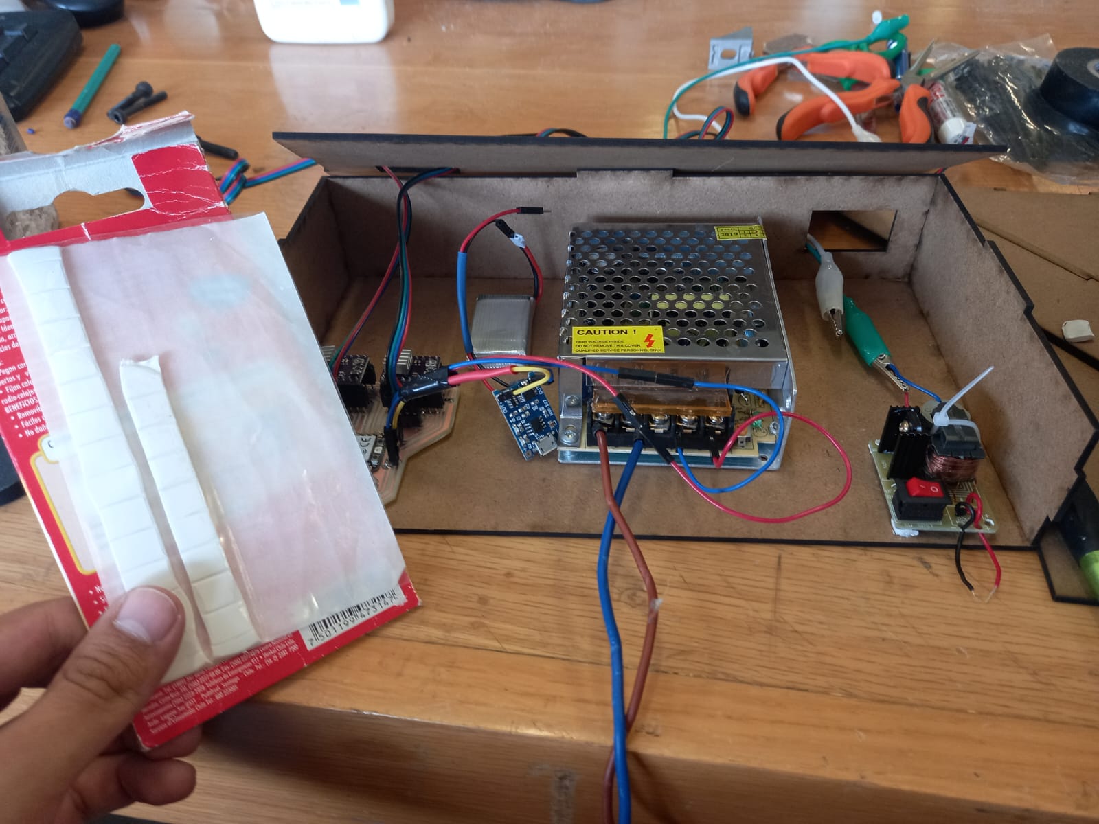
For the power supply, here we see a 60V one, but in the end, I used a 12V supply. However, this image clearly explains that the wires are connected to Neutral (N) and Line (L) for connection to household electricity. Similarly, the +V and -V outputs are related as follows: the first +V output connects to the first -V output, and so on.
Here we can see an aerial view of the machine prototype. However, it still needs to be packaged as everything looks very disorganized.
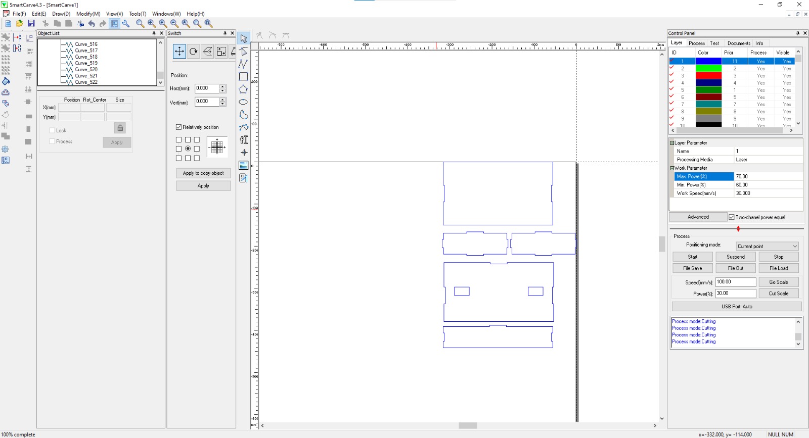
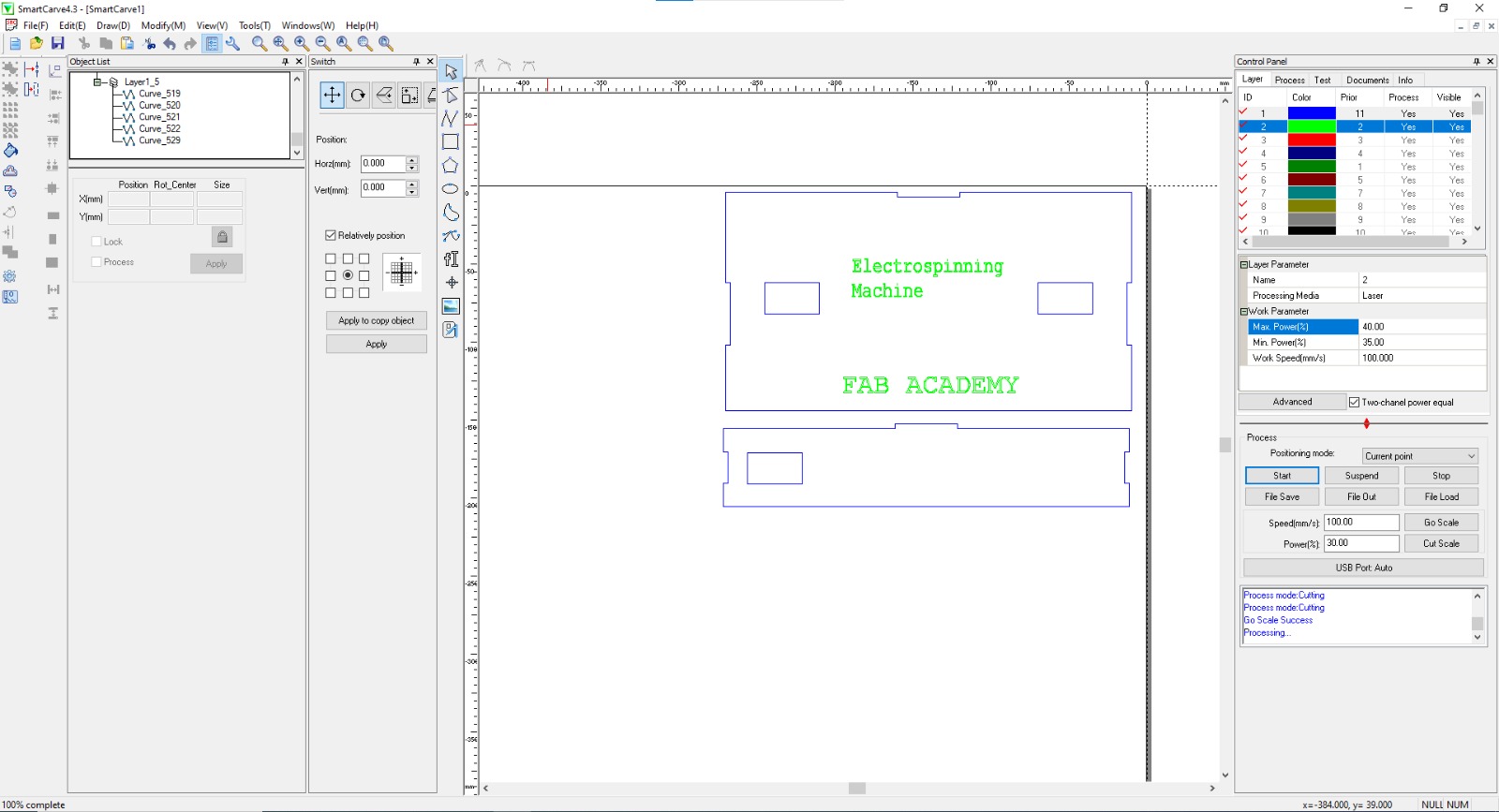
To package everything, I decided to make an MDF box with laser cutting and engrave the project's name and Fab Academy on the top. For cutting, I used the following parameters - Max Power (%): 70, Min Power (%): 60, Work Speed (mm/s): 30. For engraving - Max Power (%): 40, Min Power (%): 35, Work Speed (mm/s): 100
Assembling the box.
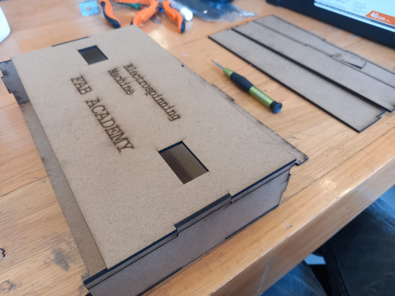
Here is the machine!
License
The goal of this project is to enable students and anyone interested to use the electrospinning technique for their own projects. Additionally, we aim for other institutions to build their own machines using this step-by-step guide. However, I leave the possibility of adapting and commercializing it open, leaving it to individual choice. Therefore, the by-sa license is the most appropriate and the one I choose.

Special thanks
I'm very grateful to the following people for helping me with the idea, providing practical and theoretical knowledge, and offering their constant support:
My parents: Luis Cuautle and Aida Ortiz.
Gregorio Romero de la Vega.
Ramzi del Angel Mellado Pumerino.
Oliver Ochoa García.
And all my FABLab friends.