11. Inputs Devices
First of all, you will find analog and digital inputs on our group webpage (click here).
Sensors play a fundamental role by serving as electronic elements capable of perceiving the surrounding environment. From temperature detection to the measurement of biological signals, according to the National Institute of Biomedical Imaging and Bioengineering, sensors are tools that detect and respond to some type of input from the physical environment. These devices are essential in various applications in fields such as medicine, industry, and research. The ability of sensors to capture and respond to physical, chemical, or biological stimuli makes them fundamental tools in technology.
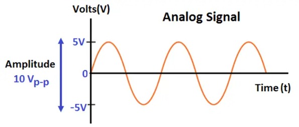
Analog sensors use continuous waveforms to provide continuous measurements and display a range of states based on the physical magnitude they detect.
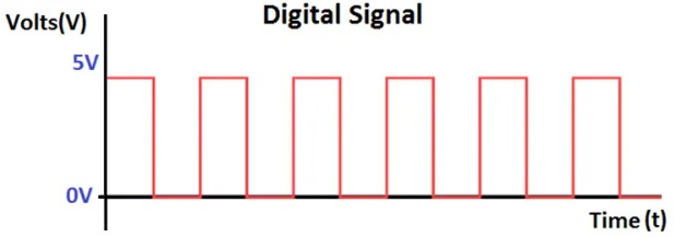
Digital sensors use non-continuous signals and represent binary values that can only be interpreted as zeros or ones. This makes them efficient in discretization by displaying changes in the environment digitally.
Intelligent sensors possess autonomous adaptation thanks to integrated computing resources that perform predefined functions.
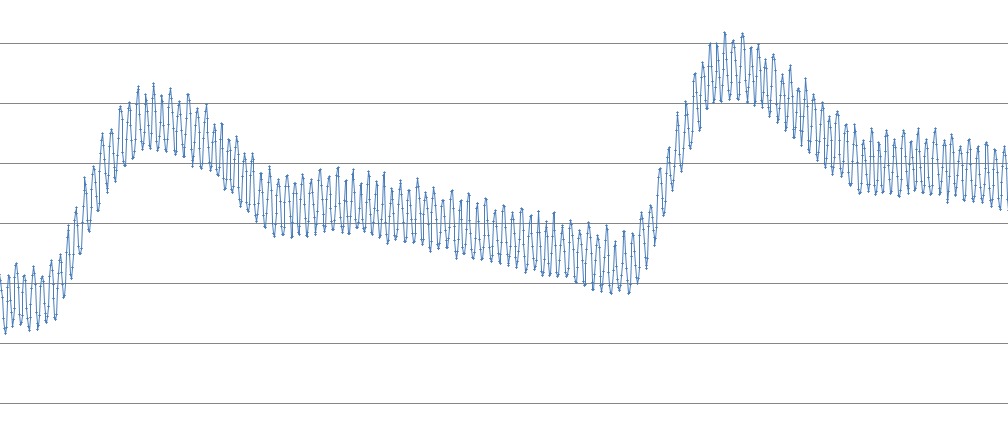
Pulse oximeter signal example
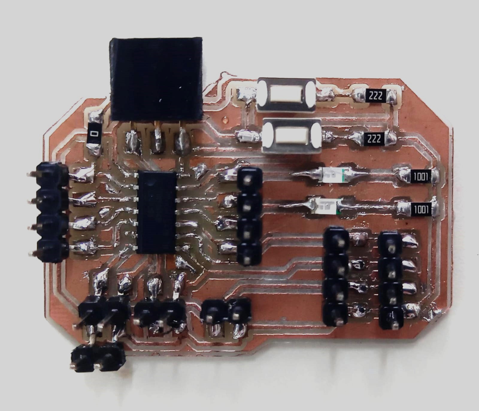
I designed a new board for this week because I broke my ATtiny44 board :C. So, for this week, I wanted more power, capacity, pins, and I wanted to program via UPDI (Unified Program and Debug Interface) to facilitate the process and the PCB design.
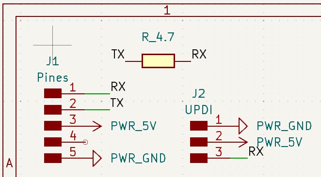
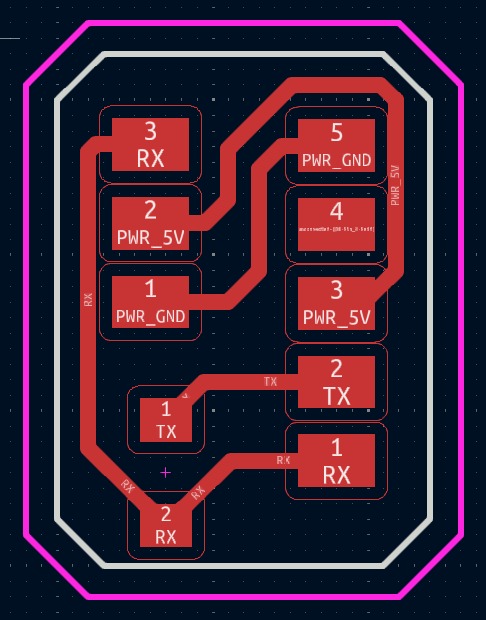
Here are the schequematic and the circuit.
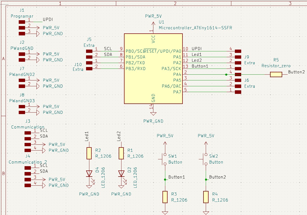

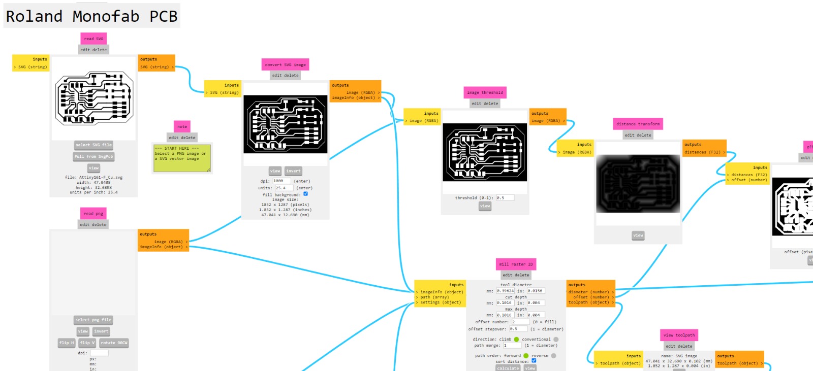
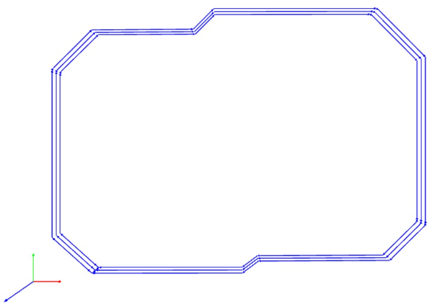
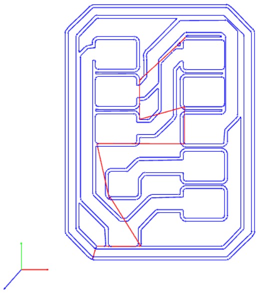
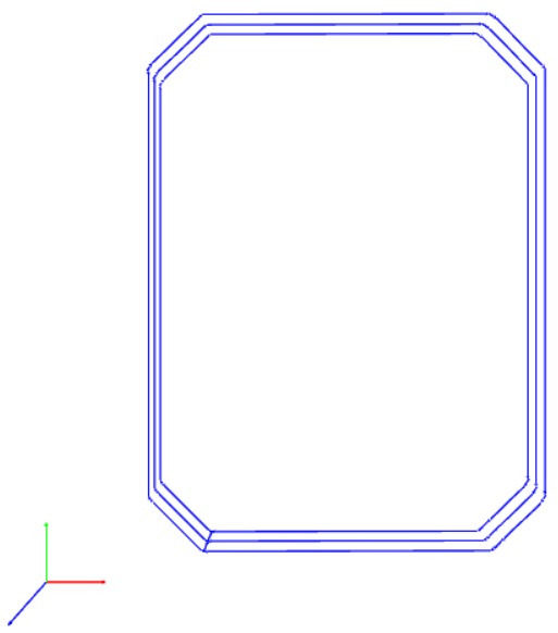
I used previous knowledge using MODS to calculate and generate rml files.

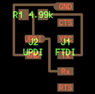
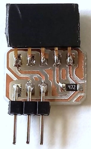
Also, I designed a UPDI target to program the board following the example proposed for Adrián Torres.
Components list
Attiny 1614
- Attiny 1614
- 2 SMD LEDs
- 2 SMD resistors (1001) for the LEDs (1000 ohms)
- 2 buttons
- 2 SMD resistors (222) for the buttons (2200 ohms)
- 1 SMD resistor (0)
- 24 male pins
- 3 female pins
UPDI
- 1 SMD resistor (472) for programming communication (4700 ohms)
- 3 male pins
- 5 female pins
I tried my best hehe.
Programming Attiny 1614
CH = Click Here
Adrian Torres's documentation is very useful for using Quentorres Hello Board XIAO RP2040 (CH) to program the ATtiny1614 via a UPDI board, but here's a summary. Why the summary? I had many problems programming it, too many I'd say, so I hope my advice proves helpful to you!
- To flash the board and prepare it for use as a programmer (CH), the easiest method is to install the UF2 firmware file available here (CH).
- Before connecting the board to a computer via USB cable, press the button labeled "B" (Boot), hold it while pressing the button labeled "R" (Reset) and then connect the board. The RP2040 will enter its reset mode; you can release the button. After that, place the UF2 firmware file on the empty hard drive that appears after releasing the button; it's like the folder opens up to you. After the file transfer, the board will automatically reset and be ready to use.
- Adrián Torres and Quentin Bolsée said: You can use the UART connector as it is, but it's also a nice way to flash a UPDI target (ATtiny 1,2 series and AVR Dx). You can either use a UART to UPDI + VCC connector or design your target with an embedded 4.7k resistor between TX and RX. I have already designed a tiny UPDI target for you, so connect it to the Quentorres board. (See the previous images and the files at the end of the web page).
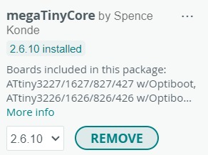
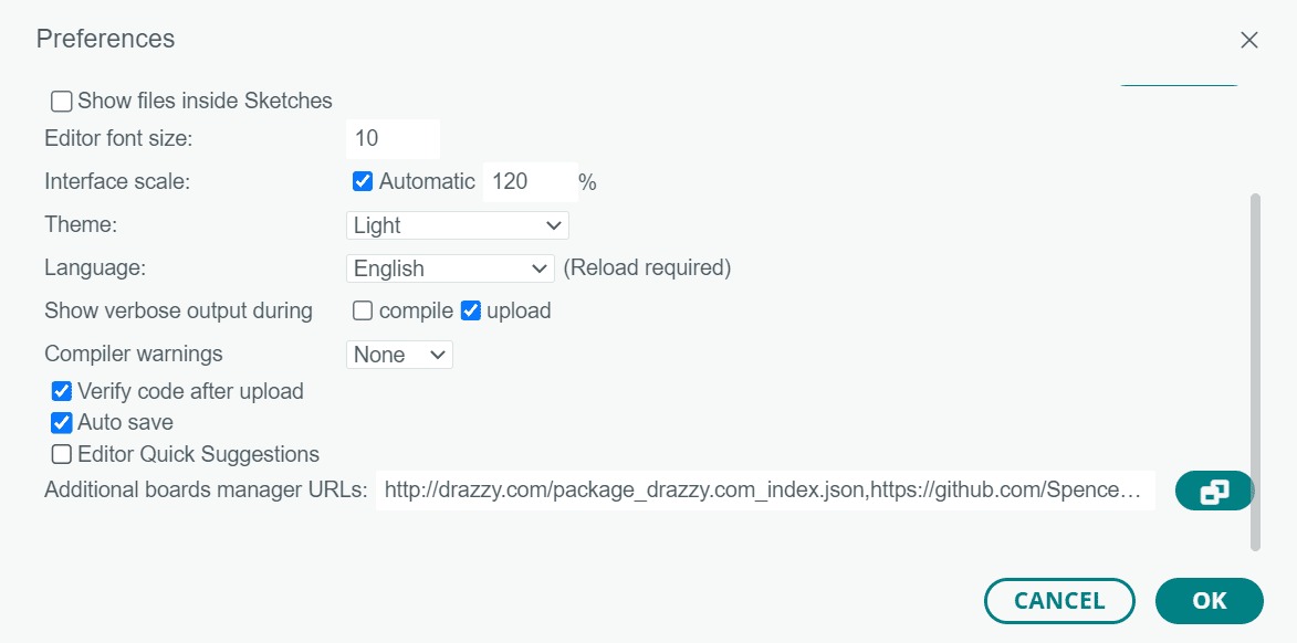
- Open the Arduino IDE and install the megaTinyCore.json file -- [http://drazzy.com/package_drazzy.com_index.json] -- in the preferences tab, then open the Board Manager and install it.
- Select the following:
- Board: Choose the option that matches your board. In my case, one that has 1614.
- Chip: "ATtiny1614" or your chip.
- Port: The port to which you are connecting your Quentorres board.
- Programmer: Serial UPDI - FAST: .4.5v+ 460800 baud (CH340 - and maybe some others).
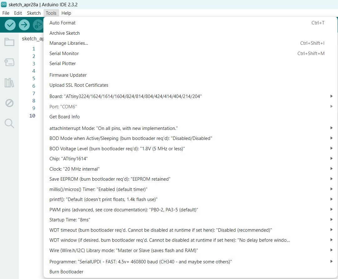
- Burn the bootloader.

Try a code! I've uploaded a blink example to check if everything is going correctly.
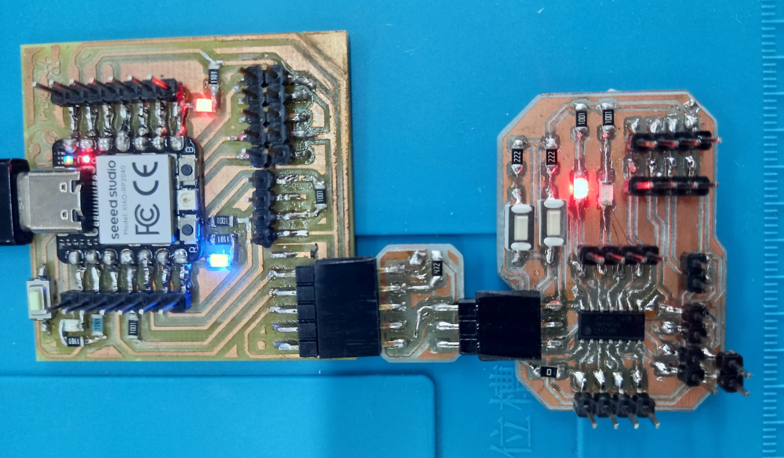
Testing
Sensors
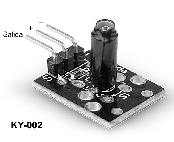
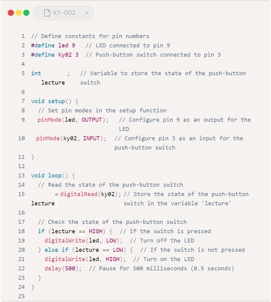
KY-002 Vibration
It's a vibration sensor that allows us to detect vibrations when subjected to an external force. It operates like a switch, which, upon detecting movement or vibration, sends a signal.
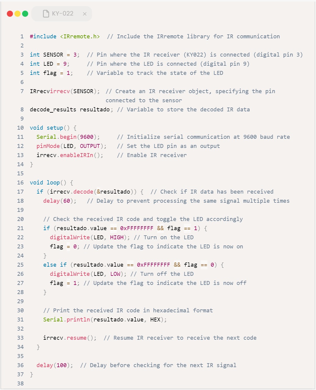
KY-022 IR (Infrared) receiver
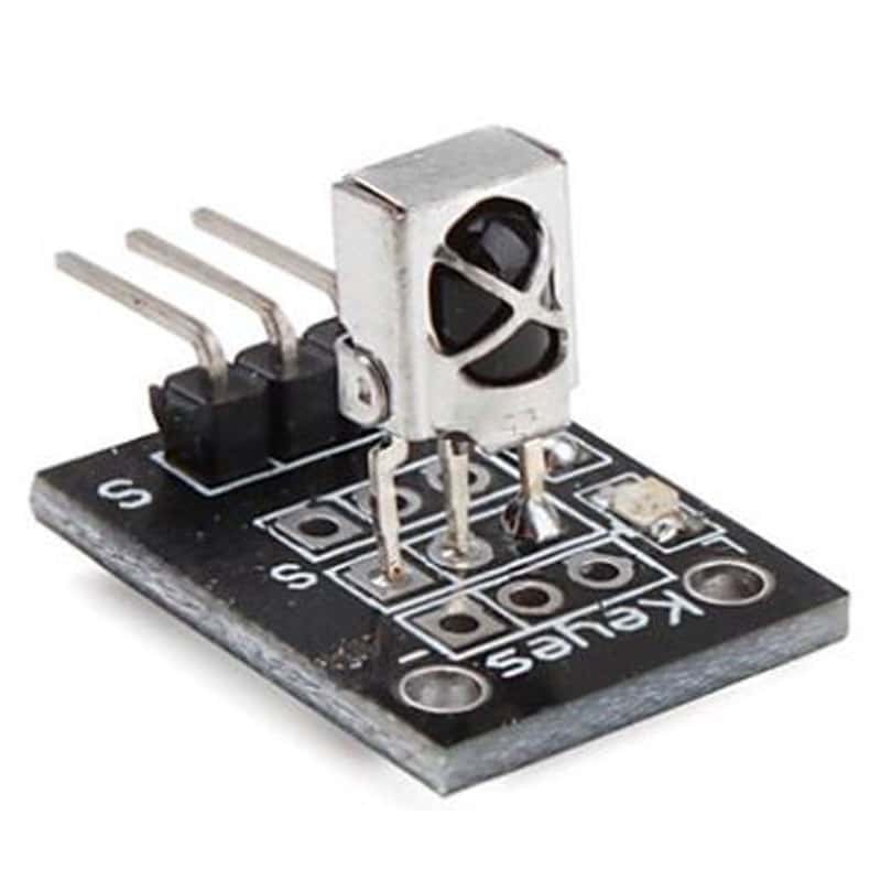
The Infrared (IR) Receiver Sensor is built with a TL1838 IR receiver, which responds to 38 KHz infrared light. This module is used in many household devices for universal remote controls, utilizing NEC encoding. It works excellently, especially in vehicles with MP3, digital photo frames, and equipped lighting systems.
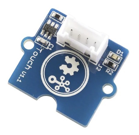
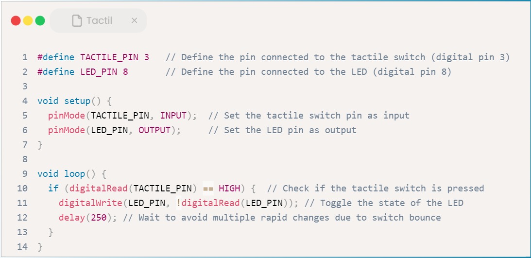
Touch
This is a touch sensor module that can be used to replace a push button. It consists of a chip that measures the capacitance of a film. It can detect changes in capacitance and thus determine when the button is being pressed.
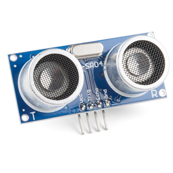
Ultrasonic
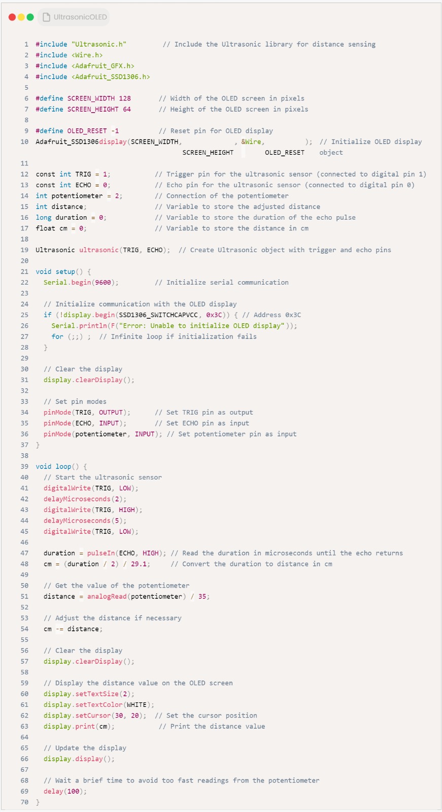
The sensor head emits an ultrasonic wave and receives the wave reflected back from the target. Ultrasonic Sensors measure the distance to the target by measuring the time between the emission and reception.
OH No, Where is the problem?
To begin with, no code was uploading, and the bootloader wasn't burning. I kept getting ERROR 1, so I panicked and thought it was my UPDI target. I checked with the multimeter, but there was nothing unusual. Then I decided to reread the documentation and realized... I didn't put the Quentorres in programmer mode :C. After that, it did burn the bootloader. However, I encountered the following error:
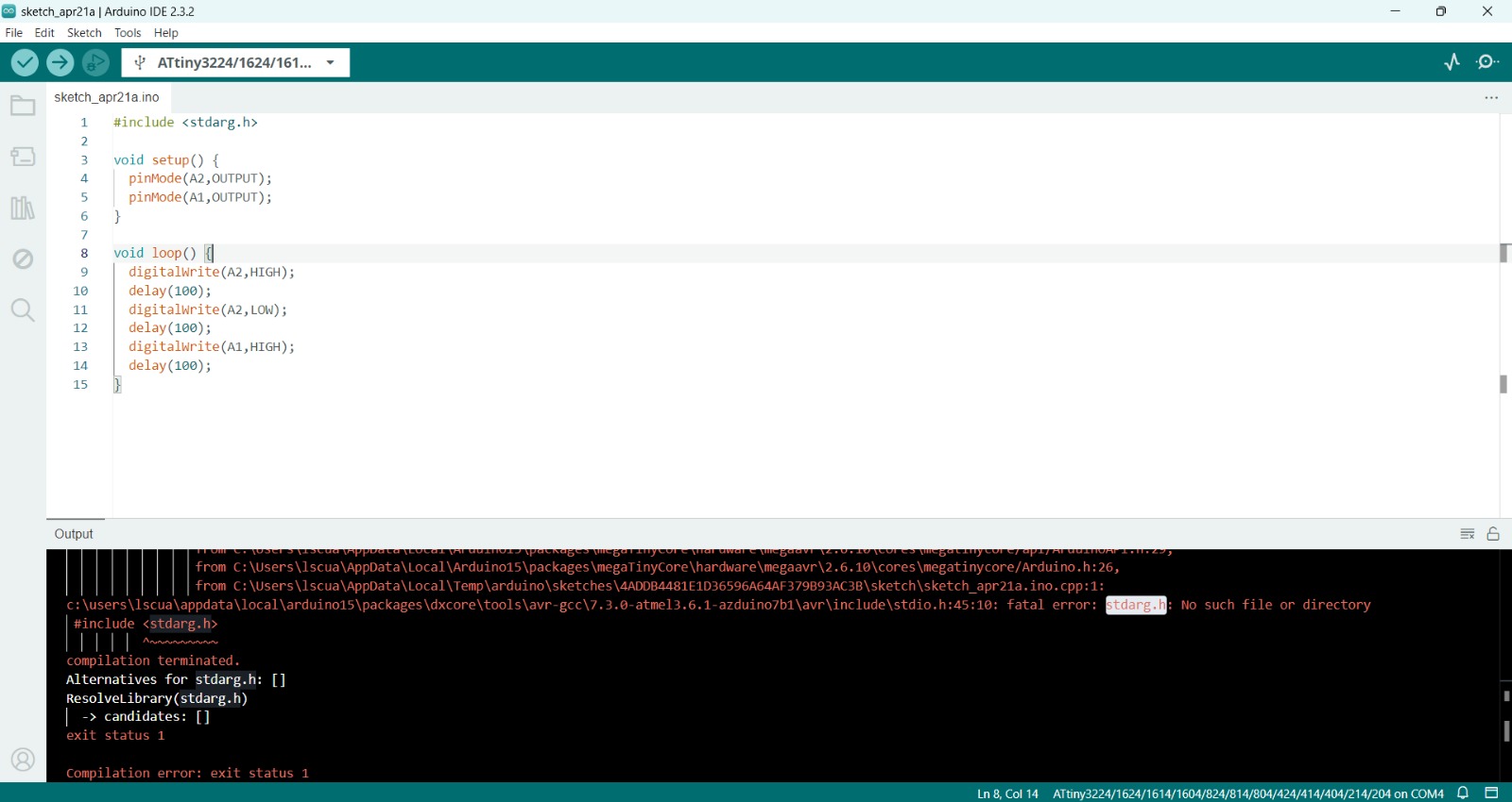
This means that megaTinyCore was not installed correctly in the Board Manager tab, so Remove it and Reinstall it to correct the error. And that's it.
