9. Output Devices
First of all, in our group webpage (click here), you will find relevant information about power consumption of an output device.
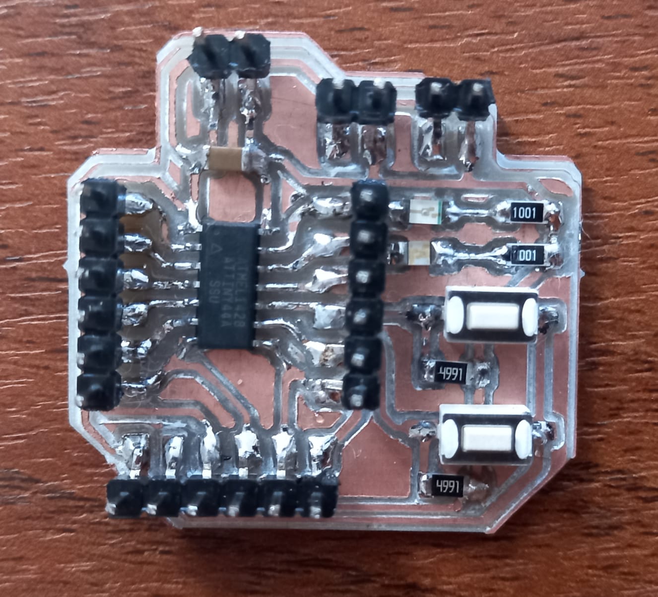
For this assignment, I'm going to use my Attiny 44 circuit board (Click here) designed the last week, I want to use a micro servomotor (3.3 Volts), an Oled display (3.3 Volts), and a stepper motor (5 Volts).
To begin, it's important to understand the signal principle of the PWM (Pulse Width Modulation), this controls the amount of time during which an electrical signal is in a high state (on) within a specified time period, namely a periodic square wave signal. This method is commonly used to regulate the speed of motors and the brightness of LEDs. The duty cycle of a periodic signal is the width of its positive part, in relation to the period. It is expressed as a percentage, so a duty cycle of 10% indicates that it is high for 10 out of 100 units of time.
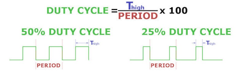
It involves activating a digital output for some time and keeping it off for the rest, in this way, generating repeating positive pulses. Therefore, the frequency remains constant (i.e., the time between pulse triggers), while the pulse width and the duty cycle are varied.
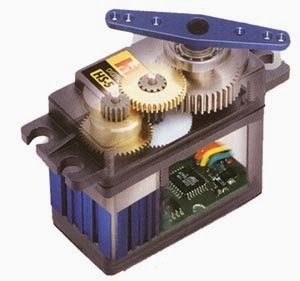
Servo motors are controlled by sending a variable width electrical pulse, known as Pulse Width Modulation (PWM), through the control cable. Typically, a servo motor can only rotate 90° in either direction for a total movement of 180°.
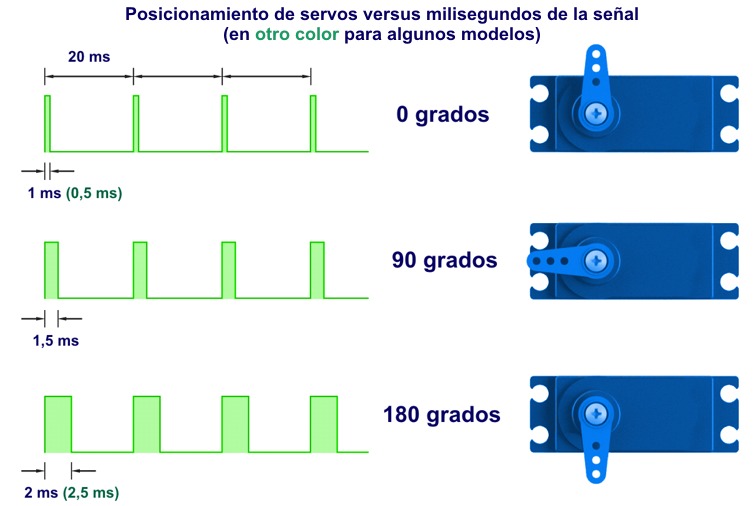
The servo motor expects to see a pulse every 20 milliseconds (ms), and the length of the pulse determines how far the motor rotates. For example, a 1.5ms pulse will make the motor rotate to the 90° position. If the time is less than 1.5 ms, it moves counterclockwise towards the 0° position, and if the time is greater than 1.5 ms, the servo will rotate clockwise towards the 180° position.
In the University we usually use two kinds of servo motors, selected based on the project requirements:
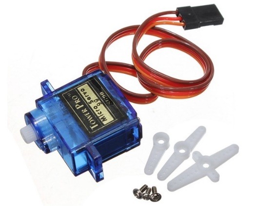 Micro servomotor with torque of 1.8 Kgf/cm
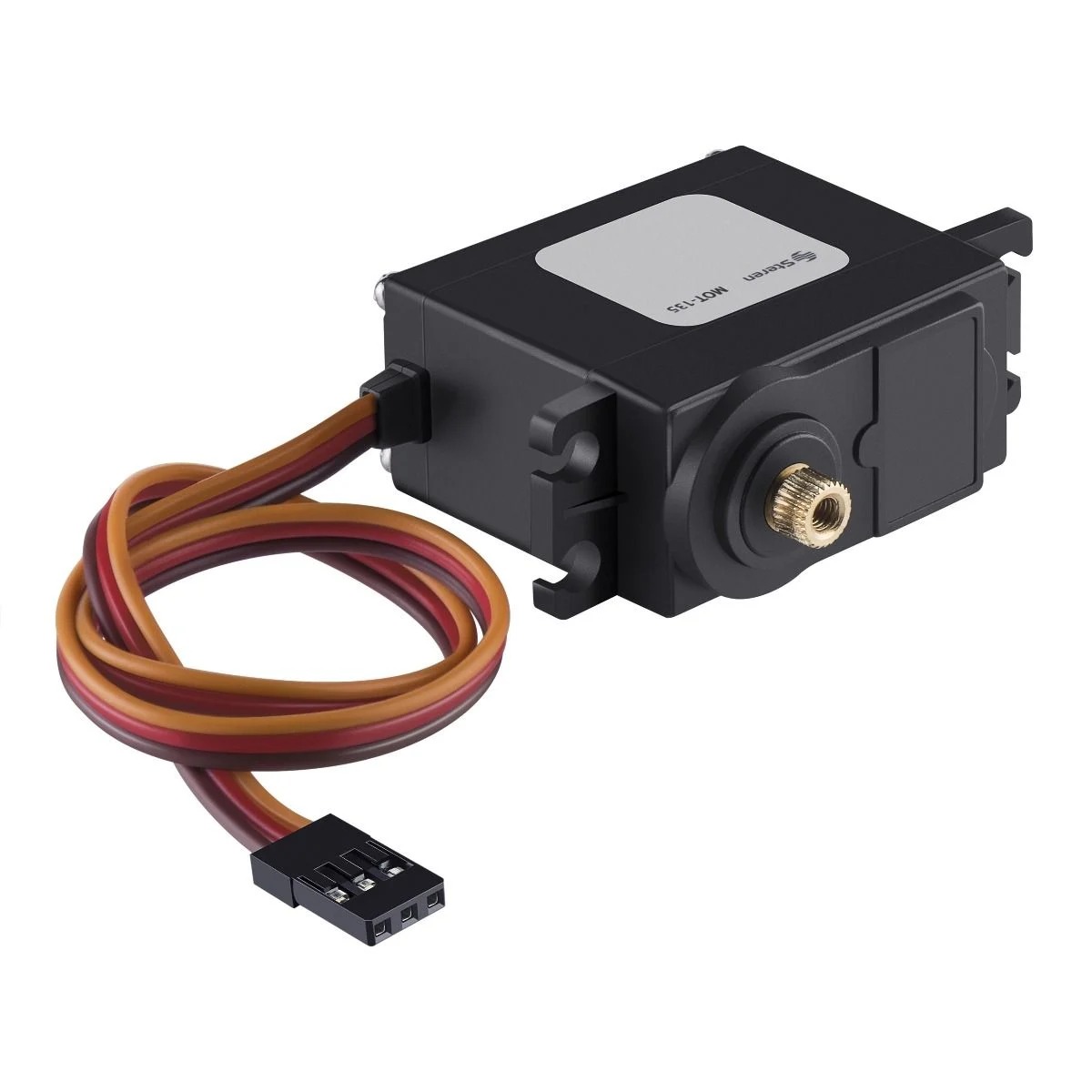 Servomotor with torque of 10 kgf/cm
To program a servo motor, we can use the "Servo.h" library to simplify the control of servomotors using pulse width modulation (PWM) signals. When using this library, you don't need to worry about the specific details of PWM, as the library handles generating the necessary PWM signals to control the servo. The name.attach() function of the Servo.h library is used to assign a specific pin of the Arduino to the servo. Then, you can use the name.write() function to send the desired angle to the servo, and the library takes care of generating the corresponding PWM signal to move the servo to that position.
First, I used Quentorres to understand the programming of the Servo.h library by turning off an LED when the servo moved from 0 to 180 degrees clockwise and turning it on when moving counterclockwise.
                        #include
                            Servo myservo;  // Create servo object to control a servo
                            int led = D0;    // Define pin for the LED

                            void setup() {
                              myservo.attach(D1);  // Attach the servo on D0 to the servo object
                              pinMode(led, OUTPUT); // Set the LED pin as output
                            }

                            void loop() {
                              int pos;

                              for (pos = 0; pos <= 180; pos += 1) { // Goes from 0 degrees to 180 degrees
                                // In steps of 1 degree
                                myservo.write(pos);  // Tell servo to go to position in variable 'pos'
                                delay(15);           // Wait 15ms for the servo to reach the position
                                digitalWrite(led, HIGH); // Turn on the LED
                              }

                              for (pos = 180; pos >= 0; pos -= 1) { // Goes from 180 degrees to 0 degrees
                                myservo.write(pos);  // Tell servo to go to position in variable 'pos'
                                delay(15);           // Wait 15ms for the servo to reach the position
                                digitalWrite(led, LOW); // Turn off the LED
                              }
                            }
Servo and LED
Then, I utilized the Attiny44 to control the servo motor, incrementing and decreasing its position by 5 degrees by pressing two push buttons. The library to move the servo with the Attiny "SoftwareServo.h" is no longer available in the Arduino library, so it has to be declared completely in the code.
Servo and buttons
OLED
OLED (Organic Light-Emitting Diode) screens are characterized by their high contrast, low power consumption (0.04w), and resolution of 128*64 pixels, allowing for control of each pixel, which is ideal for text or graphics. As well, it uses the SSD1306 module, which allows communication between the MCU to obtain data and send it to the OLED screen. Unlike LCD screens, OLED screens do not require backlighting, which means better contrast and clarity.
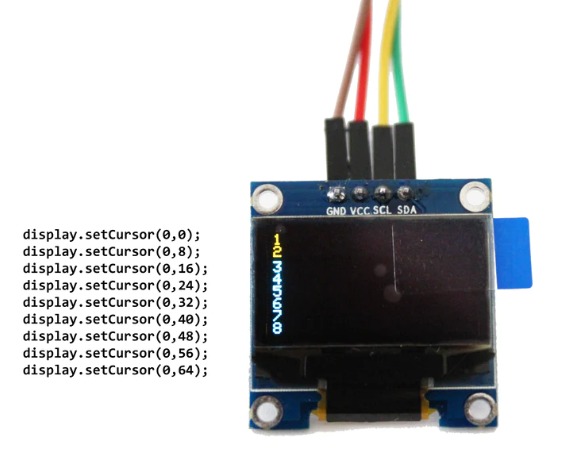
Through the I2C communication pins (SDA and SCL).
- The lines #include "TinyWireM.h" and #include "Tiny4kOLED.h" at the beginning of the code include the necessary libraries for using the I2C protocol, the Attiny44 and the OLED screen.
- prepareDisplay() function prepares the OLED display for use. It clears the display, initializes it, and sets the font size to 6x8 pixels.
- setup() function, the OLED display is initialized with a resolution of 128x64 pixels.
- oled.setCursor() function is used to set the position of the cursor on the OLED display. It determines where the next text or graphic element will be displayed on the screen.
The function takes two parameters: the x-coordinate and the y-coordinate. The origin (0, 0) is typically the top-left corner of the display, and the x-coordinate increases as you move towards the right, while the y-coordinate increases as you move towards the bottom.
For example, oled.setCursor(48, 0) sets the cursor position to the 48th pixel from the left edge of the display and the top edge of the display.
                        #include
                        #include

                        #define enPin 3

                        void prepareDisplay() {
                          oled.clear();
                          oled.begin();
                          oled.setFont(FONT6X8);
                        }

                        void setup() {
                          oled.begin(128, 64, sizeof(tiny4koled_init_128x64br), tiny4koled_init_128x64br);
                          oled.clear();
                          oled.on();
                          prepareDisplay();
                          oled.setFont(FONT6X8);
                        }

                        void loop() {
                            if (digitalRead(3) == HIGH) {
                                oled.setCursor(48, 0);
                                oled.print("ON ");
                            }
                            else {
                                oled.setCursor(48, 0);
                                oled.print("OFF");
                            }
                        }
OLED
Stepper
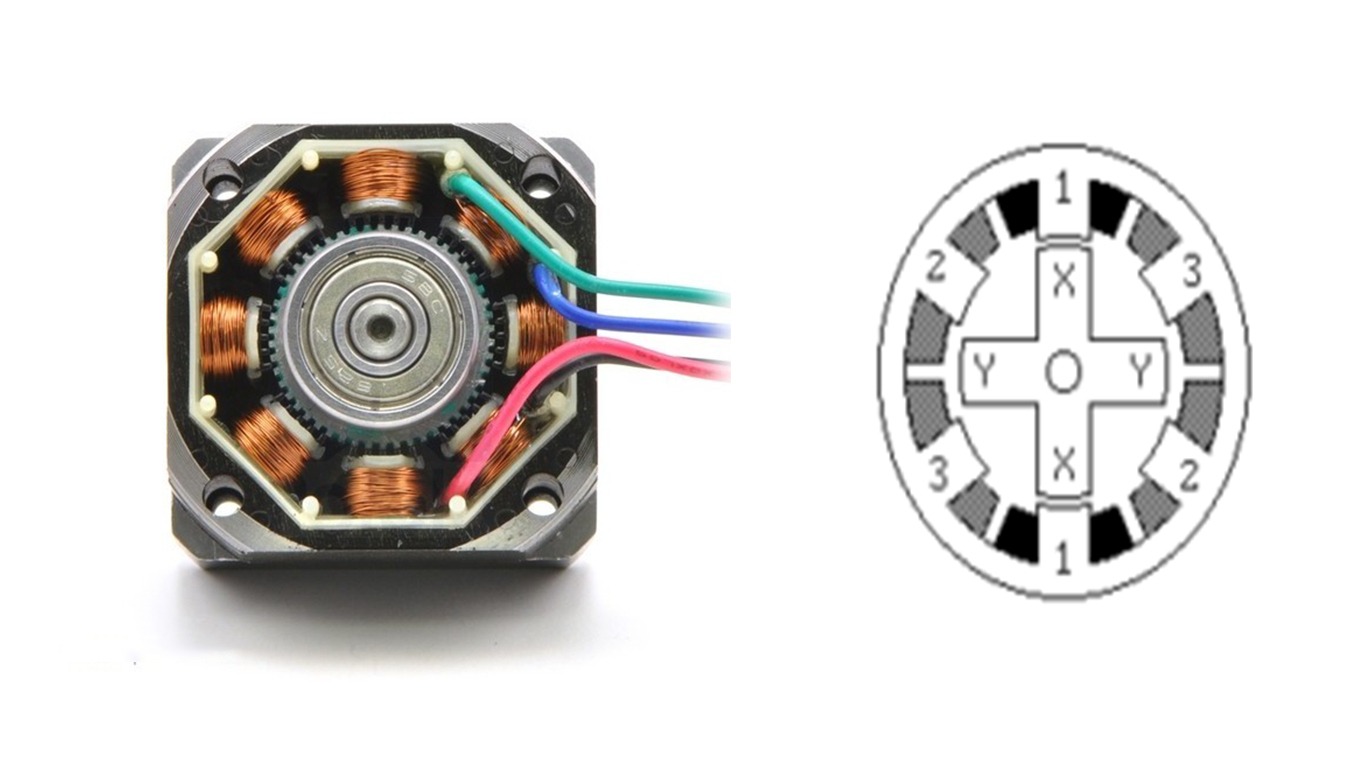
A stepper motor is a type of motor that converts electrical pulses into discrete and precise movements. It utilizes an electromagnetic design to rotate the shaft in discrete steps or predefined angles instead of continuous rotation. This makes it ideal for applications that require precise positioning, such as 3D printers, CNC machines, and robots.
The last semester I made a peristaltic pump. This is a device that moves liquids using a flexible tube that is compressed and decompressed at specific points by rotating rollers, thus generating a controlled directional flow of the liquid.
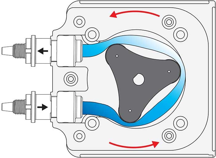
It allows for precise dosing of chemicals in industrial processes, administration of medications in medical applications, and transfer of liquids in laboratories for experiments and analysis. Its design enables smooth pumping without contamination of the transported liquid.
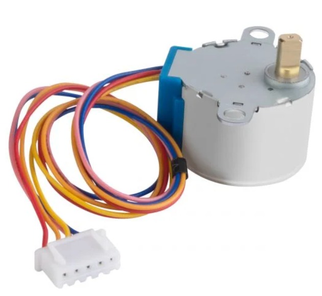
I used an ARD-300 control board for the 28BYJ-48 stepper motor. This board works with a UNL2003A driver to energize the motor coils.
 Stepper
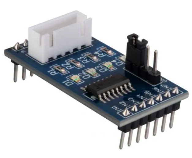 Driver ARD-300
This is the code to program each motor coil individually, I don't recommend the "Stepper.h" library because you should wait for the stepper motor to turn once before you increment the speed or change the direction, and sometimes, doesn't work.
Moving the stepper motor
Peristaltic Pump
Controlling the speed and direction
Peristaltic Pump and Buttons