Week 10 Input devices
Task: Input Devices
This is the group assignment Website Fab Lab Puebla
- Group assignment:
- Probe an input device(s)'s analog levels and digital signals
- Document your work on the group work page and reflect on your individual page what you learned
- Individual assignment:
- Measure something: add a sensor to a microcontroller board that you have designed and read it.
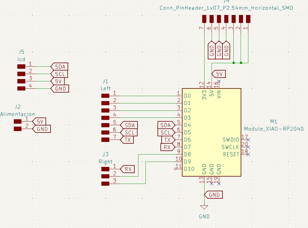
This week, during the input devices assignment, I decided to focus on the first part of my project, where I will use a light sensor to calculate the wavelength of a specific light beam. After that, I developed a second board. This board, which I had already included in my electronics device week, features a Xiao RP2040 microcontroller. The only additions I made were the input and output connections for the GPIOs, which I connected to multiple female pin headers. I also added several voltage and GND inputs because it is crucial to maintain a common ground among all the devices I will connect.
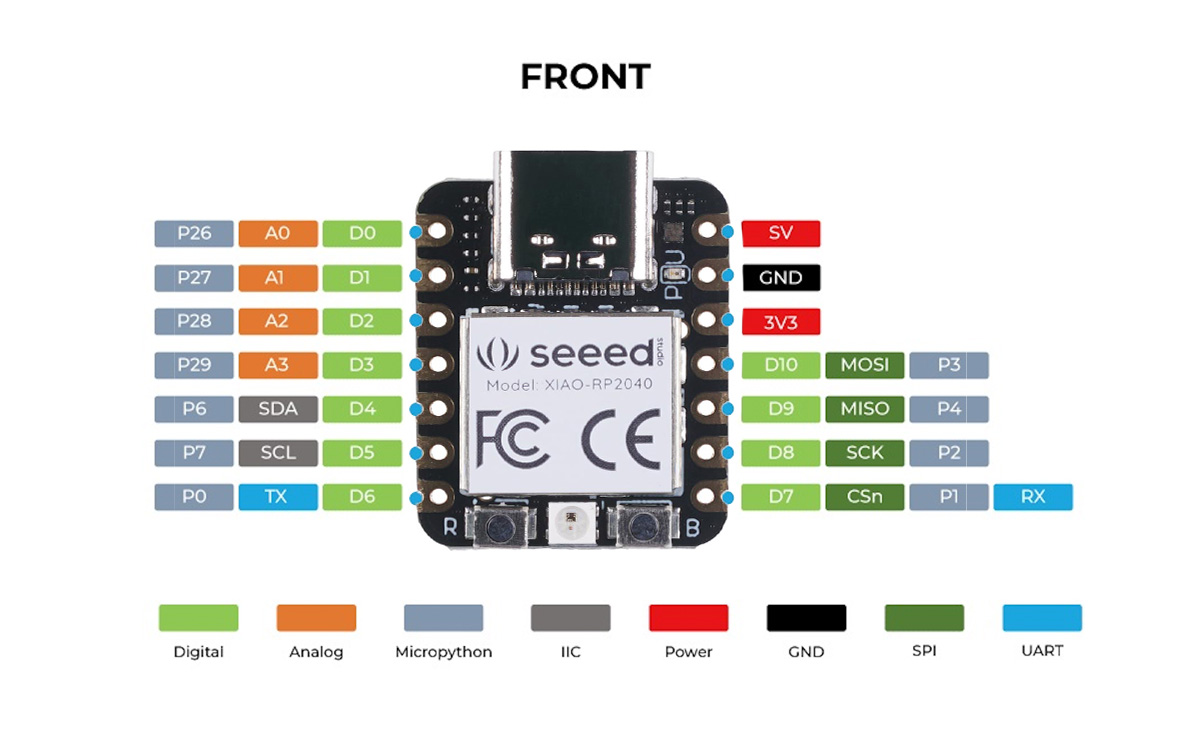
Pinout Xiao RP2040
Later, during the networking connections week, we will need a common ground, so I took advantage of this board to design it with multiple ground connections to avoid future issues. Additionally, I reserved four pins specifically for I2C connections. These I2C connections are located on GPIO4 (SDA) and GPIO5 (SCL). These are essential for establishing I2C communication.
BH1750 pin out
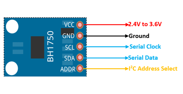
Basically, I connected them as follows via I2C connection.
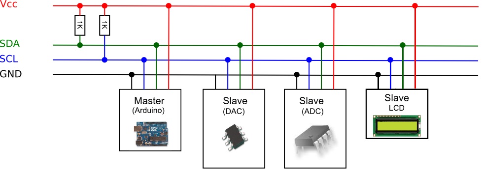
How I2C Works
I2C (Inter-Integrated Circuit) is a communication protocol that uses two wires:
- SDA (Serial Data): Transfers data.
- SCL (Serial Clock): Synchronizes data transfer.
How It Works:
- The master controls communication, while slaves respond when addressed.
- Each slave has a unique address.
- The master sends a start signal, followed by the slave's address.
- Data is transferred between the master and the addressed slave.
- The master sends a stop signal to end communication.
Key Benefits:
- Only two wires are needed.
- Multiple devices can share the same bus.
I2C is ideal for connecting sensors, microcontrollers, and other peripherals efficiently.
Ki cad PCB design
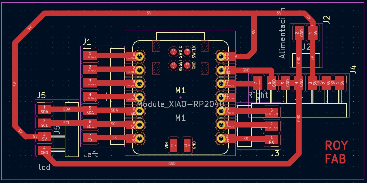
Schematic
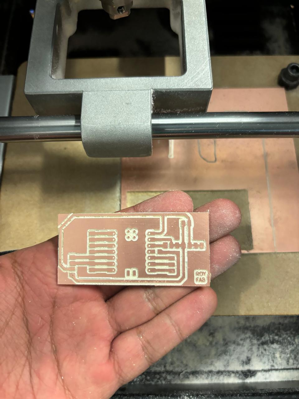
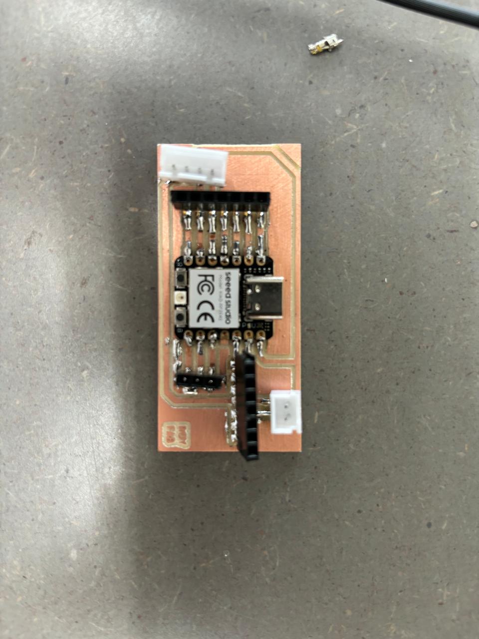
A bit of the process
I just show a few of the process but you can check more of in the previous weeks week 4 and week 8.
Here is the code of this week
                            #include <Wire.h>
                            #include <BH1750.h>

                            BH1750 lightMeter;

                            void setup() {
                              Serial.begin(9600); // Inicializar la comunicación serie
                              Wire.begin();      // Inicializar la comunicación I2C

                              if (lightMeter.begin(BH1750::CONTINUOUS_HIGH_RES_MODE)) {
                                Serial.println("BH1750 iniciado correctamente");
                              } else {
                                Serial.println("Error iniciando BH1750. Verifica conexiones.");
                                while (1); // Detener ejecución si falla la inicialización
                              }
                            }

                            void loop() {
                              float lux = lightMeter.readLightLevel(); // Leer nivel de luz en lux

                              Serial.print("Nivel de luz: ");
                              Serial.print(lux);
                              Serial.println(" lx"); // Imprimir resultado en lux

                              delay(1000); // Esperar 1 segundo antes de la próxima lectura