

My Final Project: The Campus ROVER
P2 - Drivetrain
The scooter needs a way for it's user to steer it, and this turned out easier said than done.
The drivetrain is a pretty simple mechanism that allows the front wheel to change its orientation respective to a turning axis, this change of direction in the front wheel steers the scooter. This axis is therefore connected to the handle, also providing a grip for the user.
The drivetrain also includes the instrument cluster, where data about the scooter's status is displayed, the braking system and the throttle control lever.
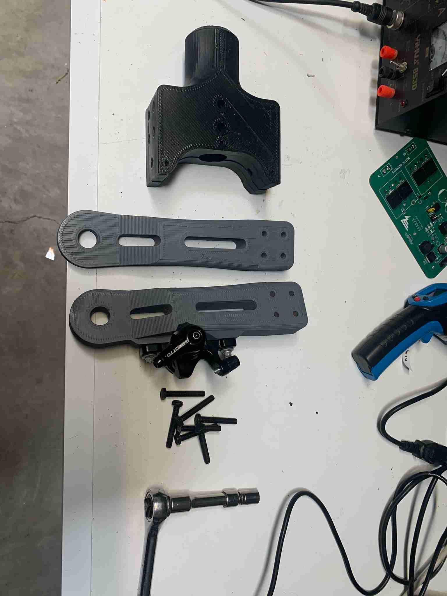
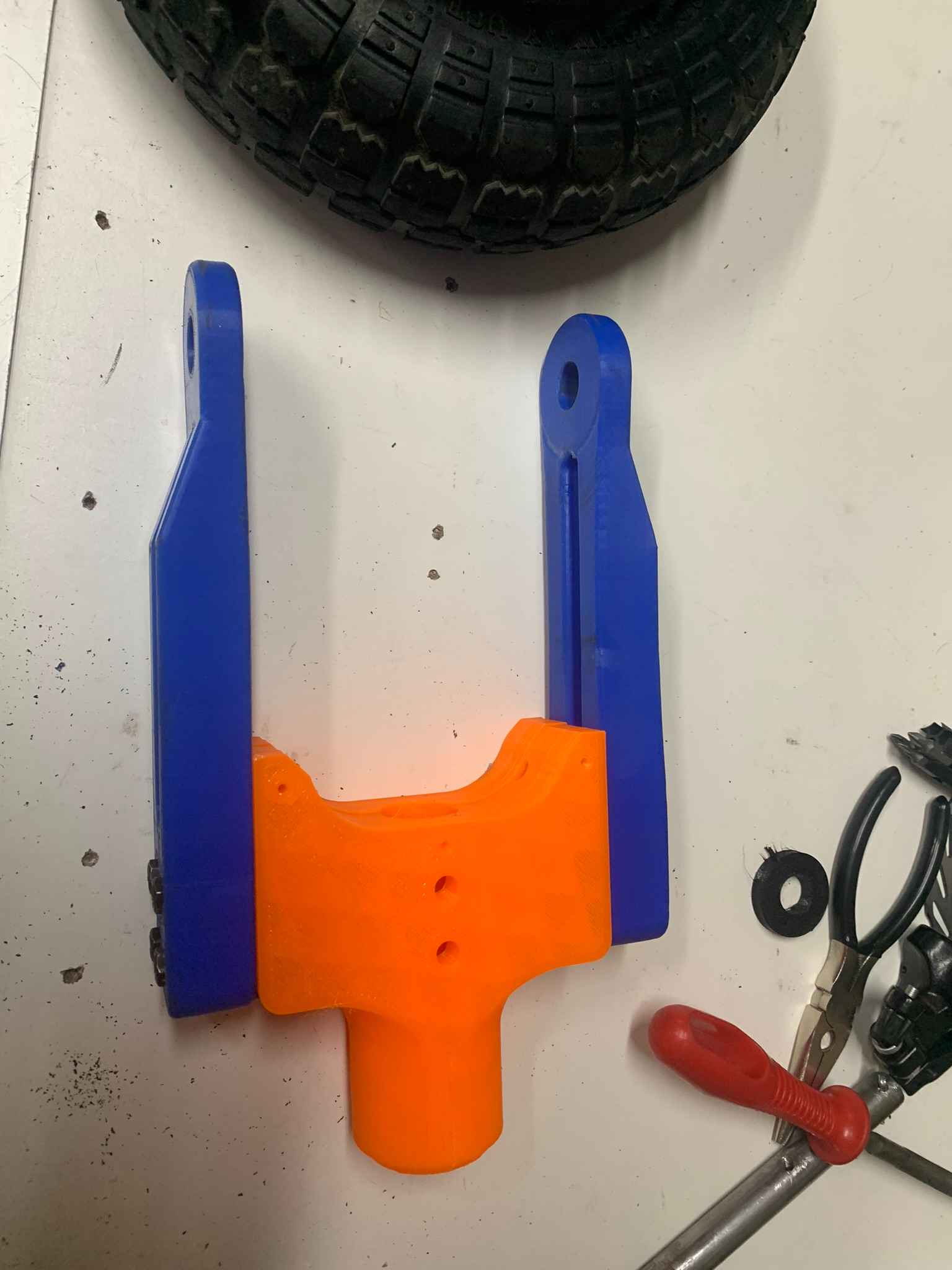
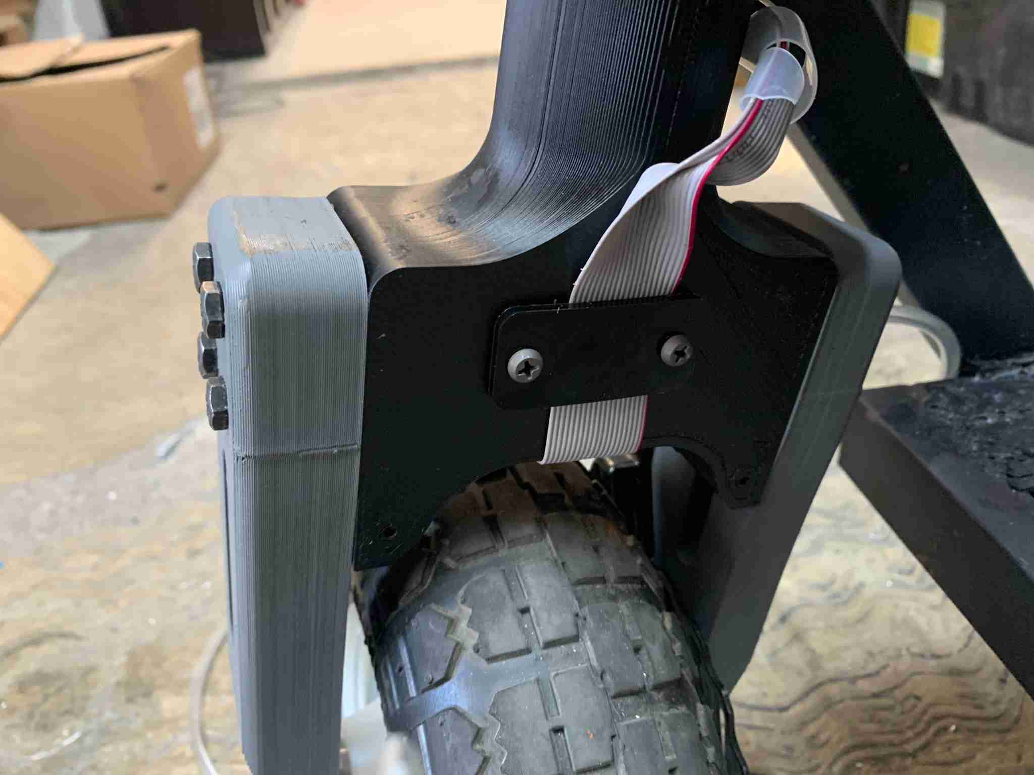
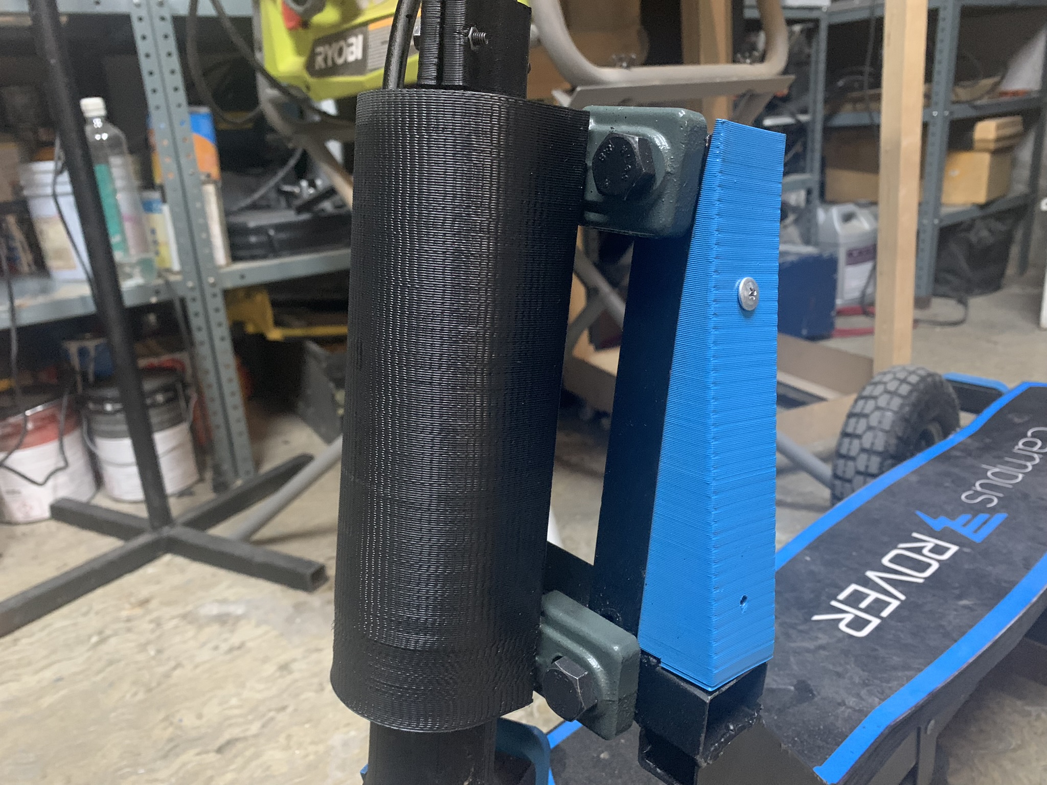
The main parts of the drivetrain are these three, which are 3D printed using high infill and allow to mount the front wheel and steer it:
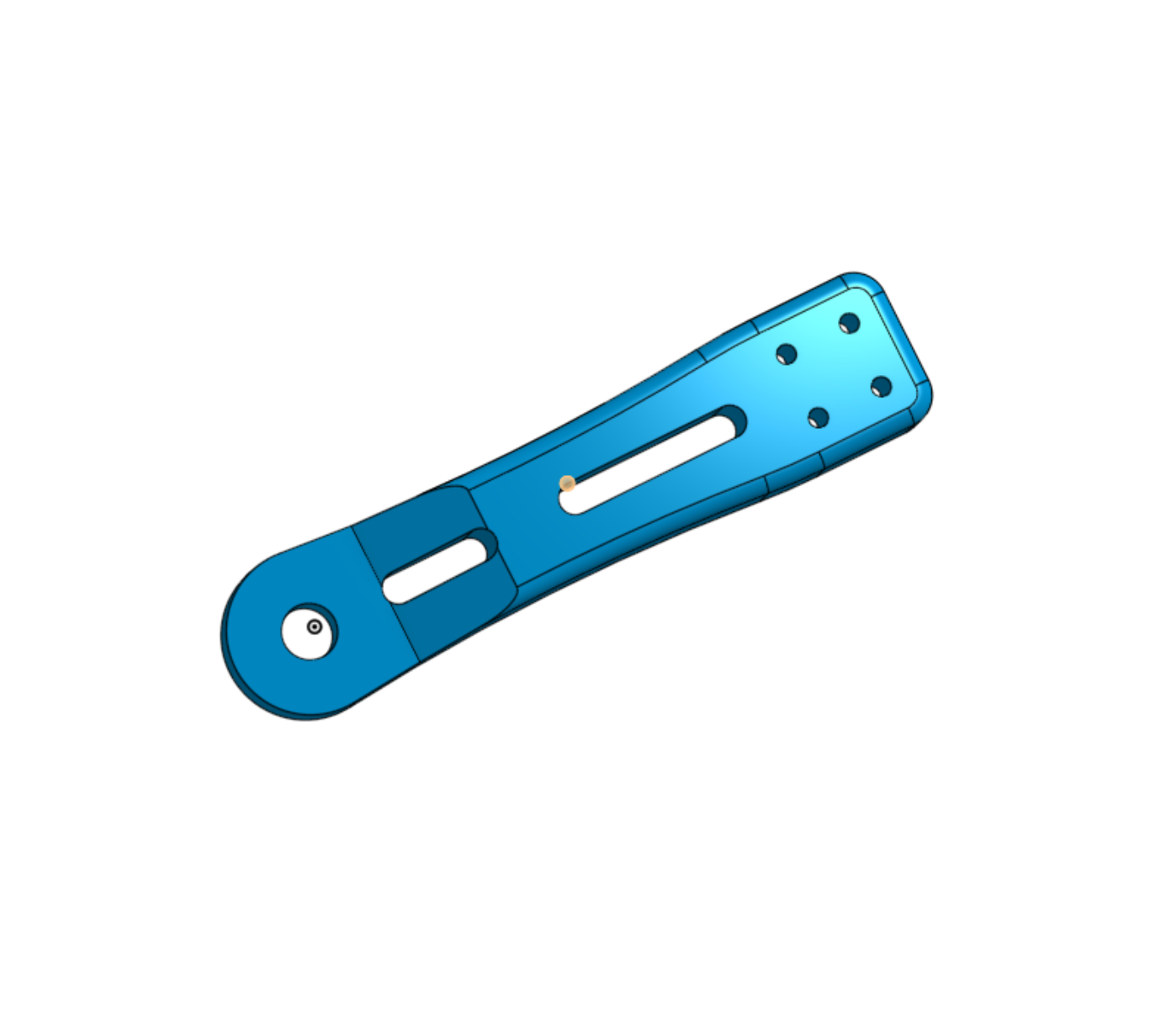
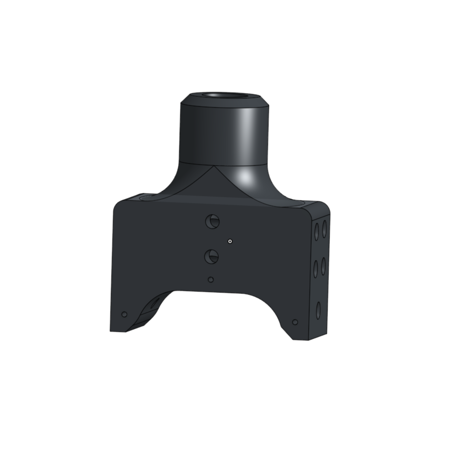
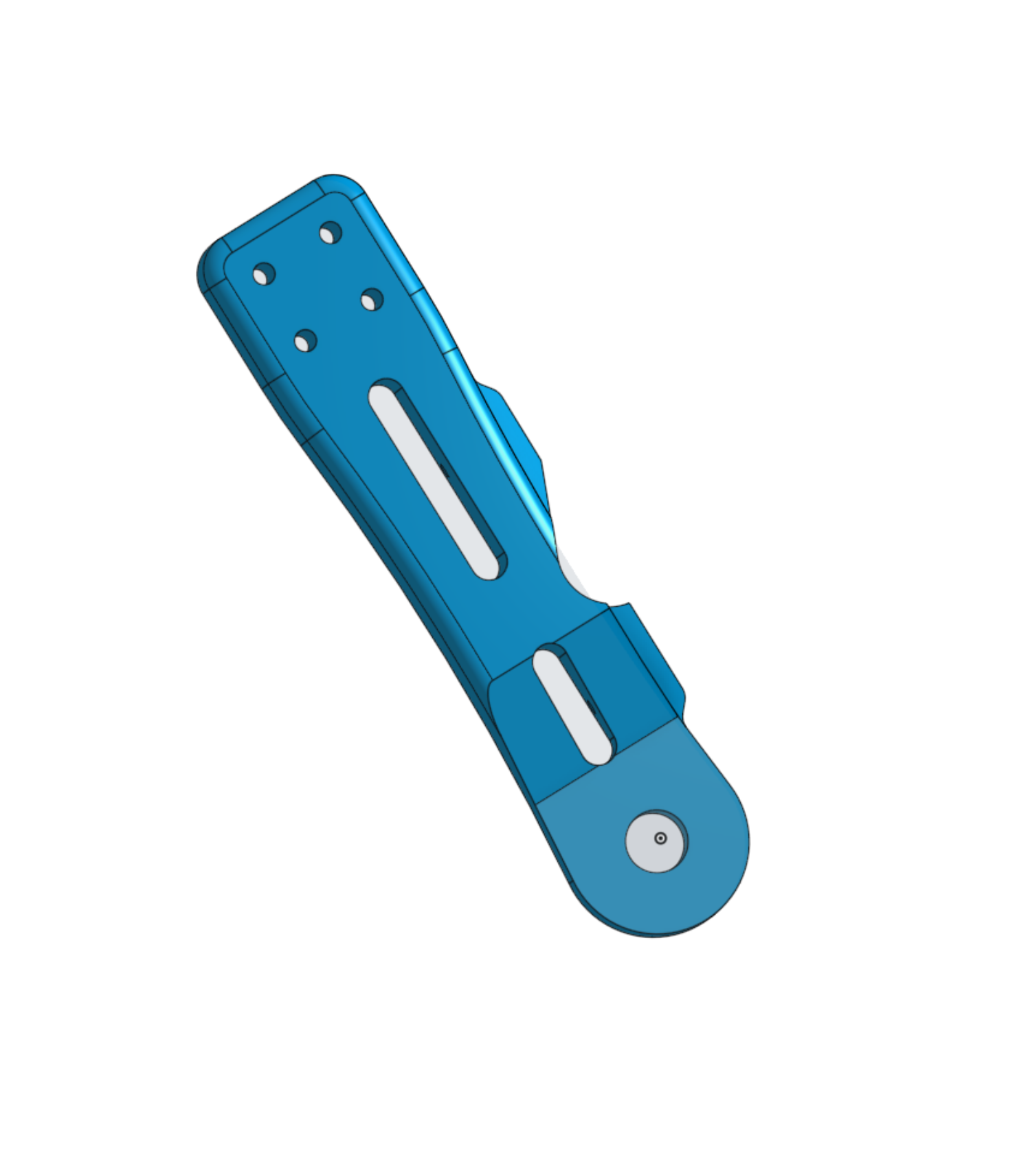
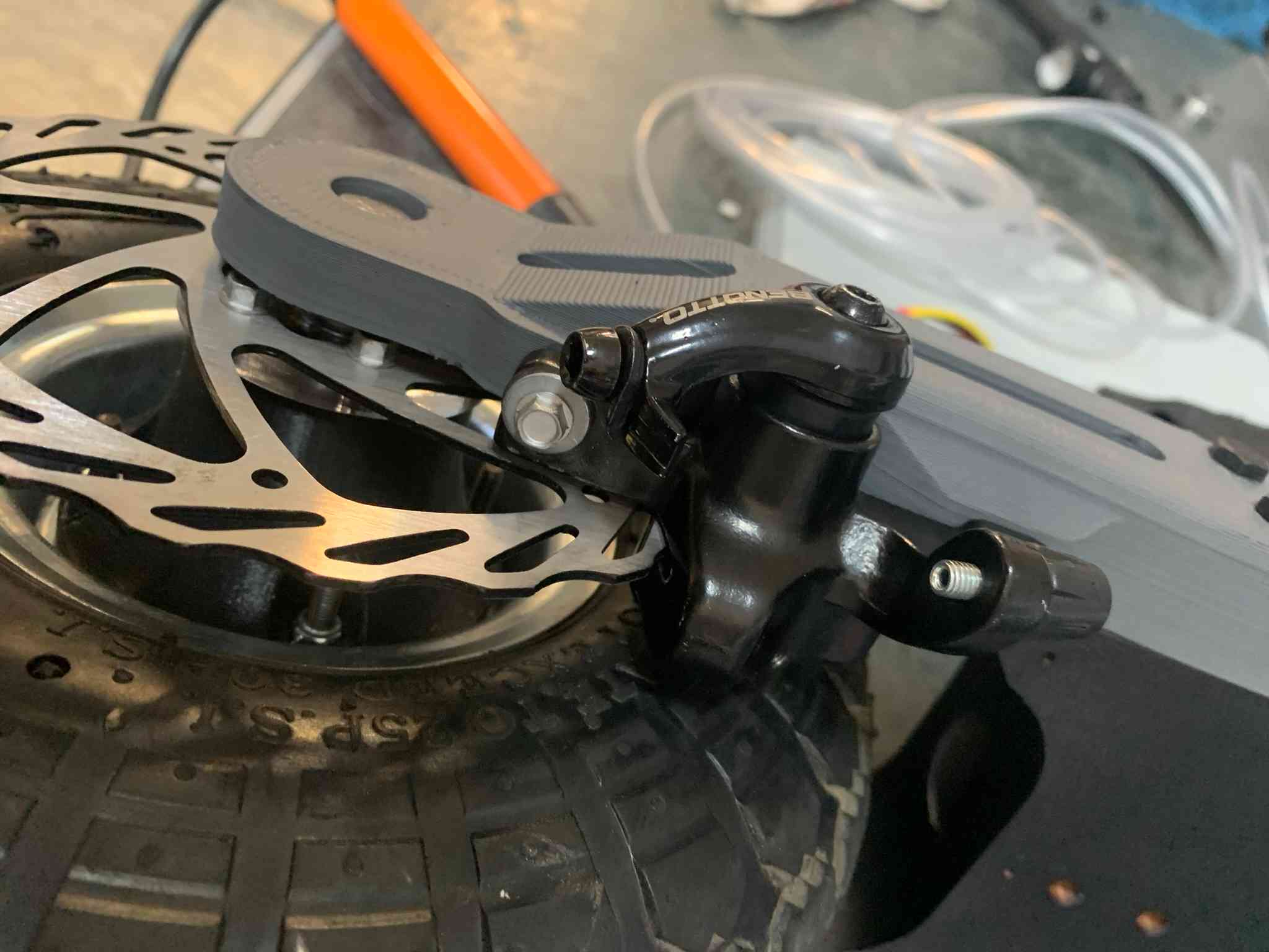
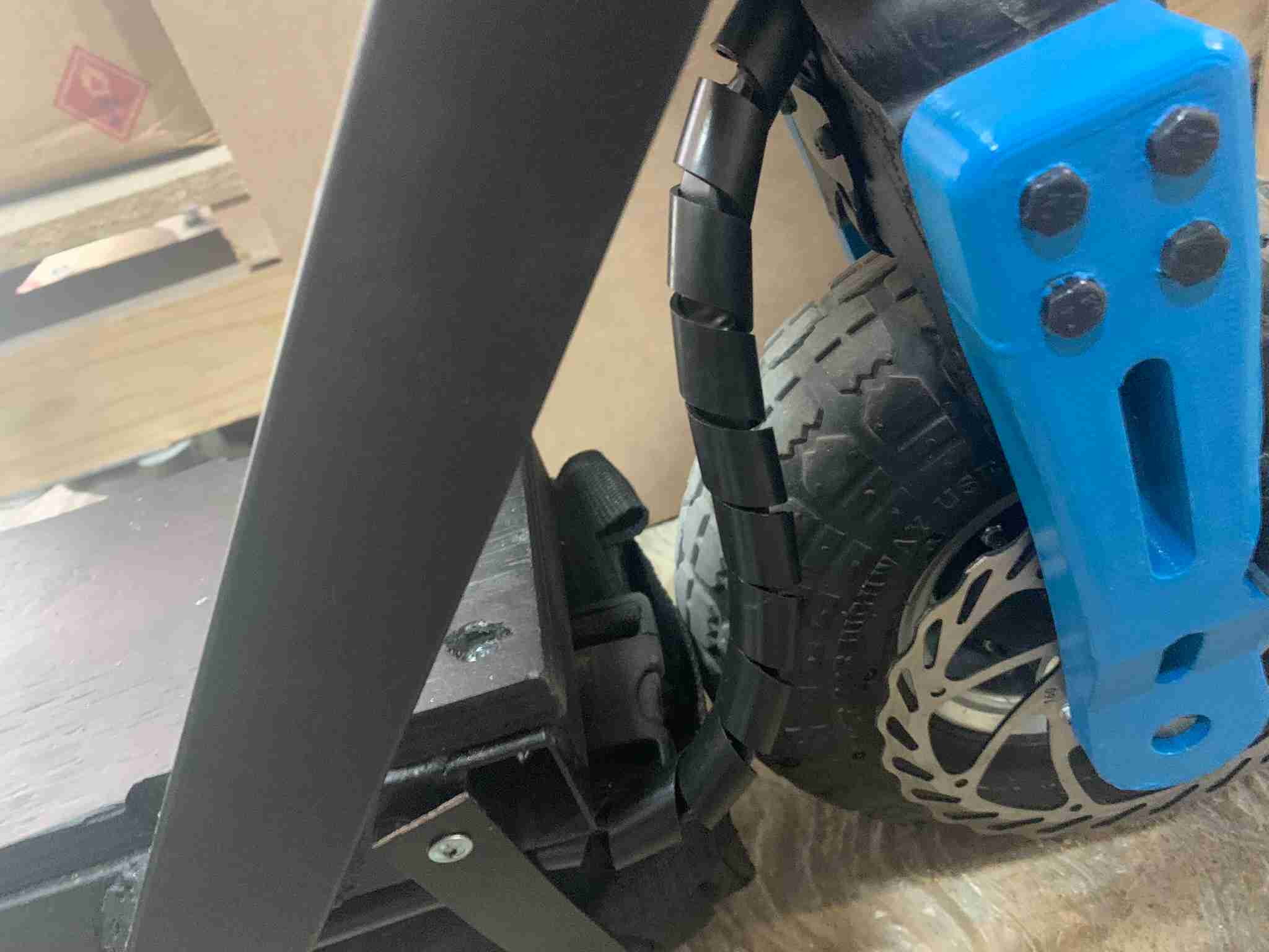
Each arm is assembled onto the main block using four M6x60 screws, and onto one of the arms, the braking pad assembly (pre-bought), is strapped using some self-tapping screws onto designated marks on the plastic:
One this is assembled, the front wheel assembly is put together using these two 3D printed parts and a pair of 5/8" by 40mm ball bearings inside the parts:
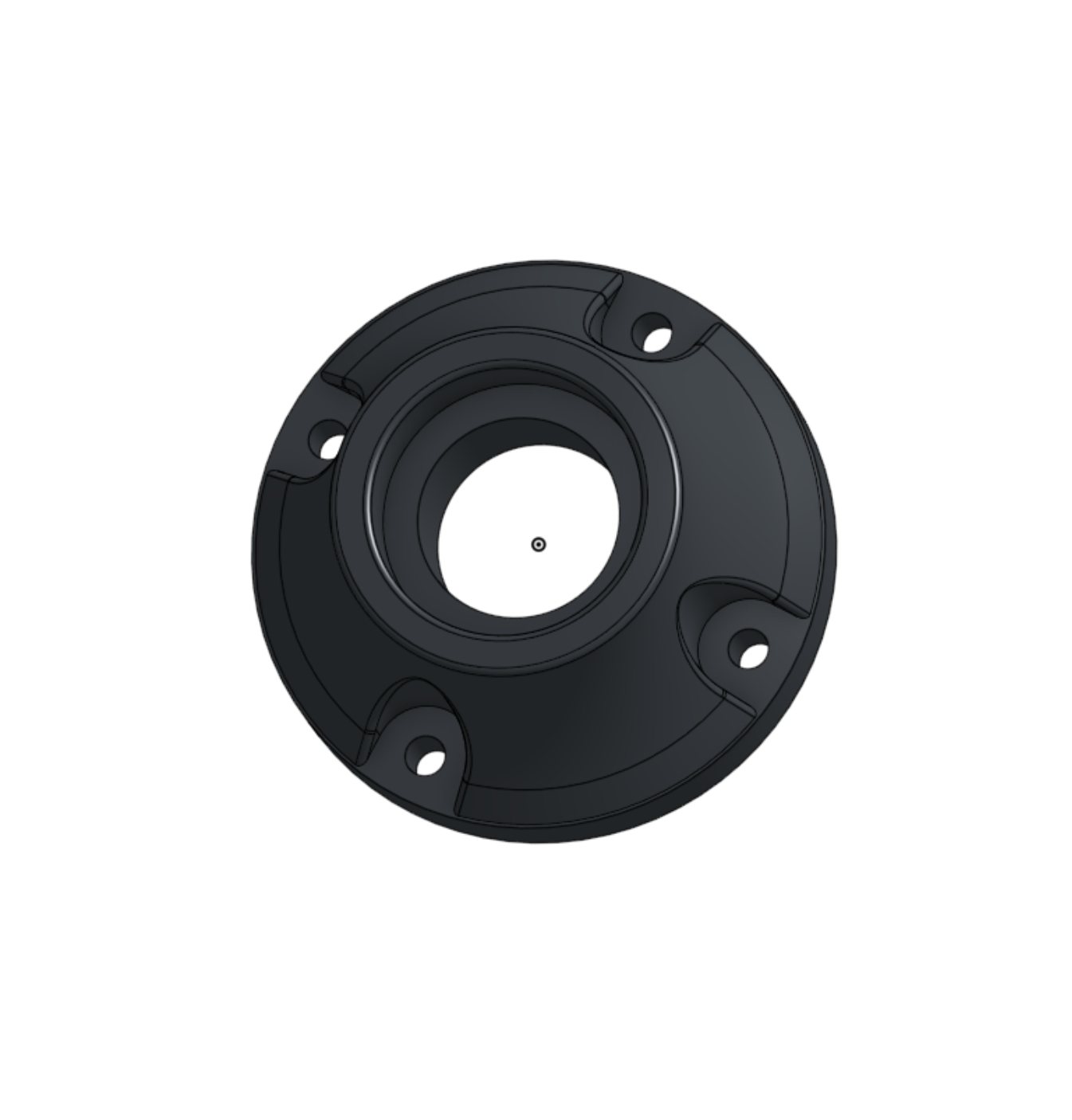
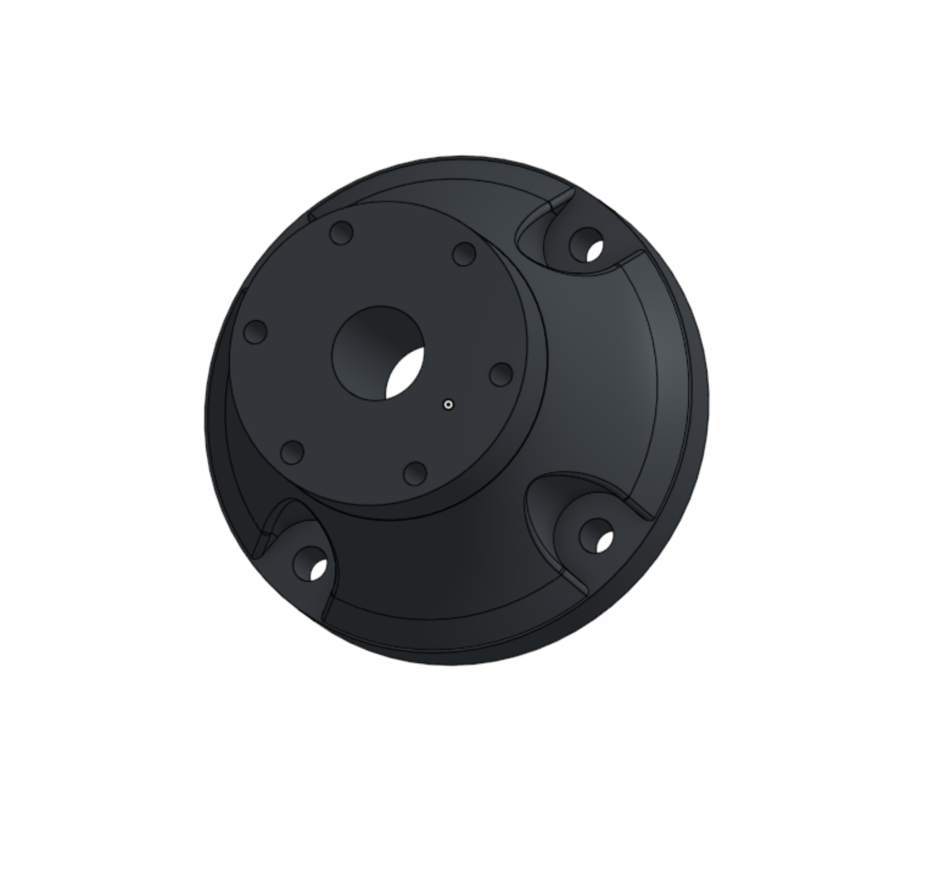
The wheel is mounted using its corresponding 5/8" steel axle and the brake pad height is calibrated so it doesn't friction with the brake disk unless the brake lever is pressed.
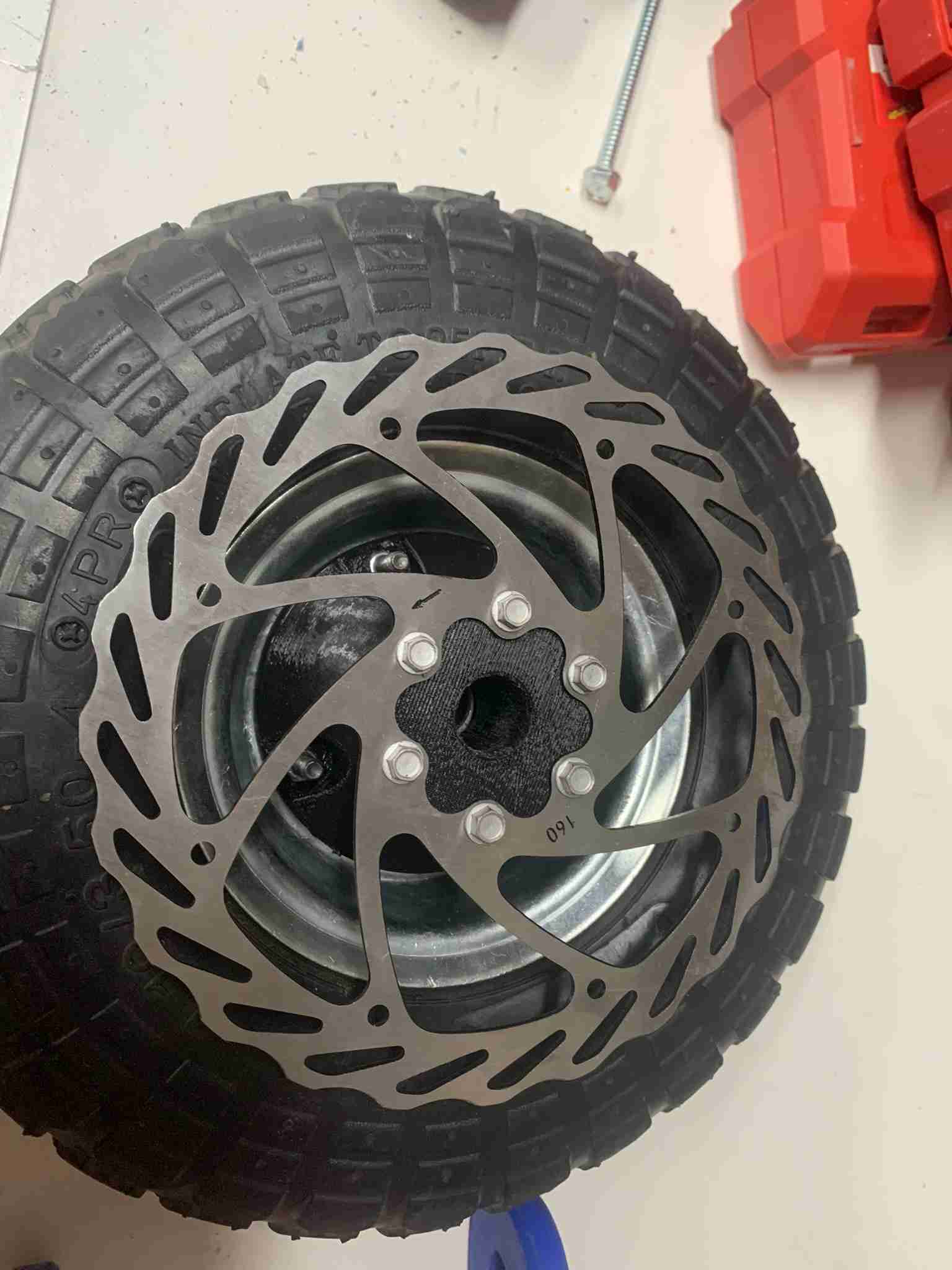
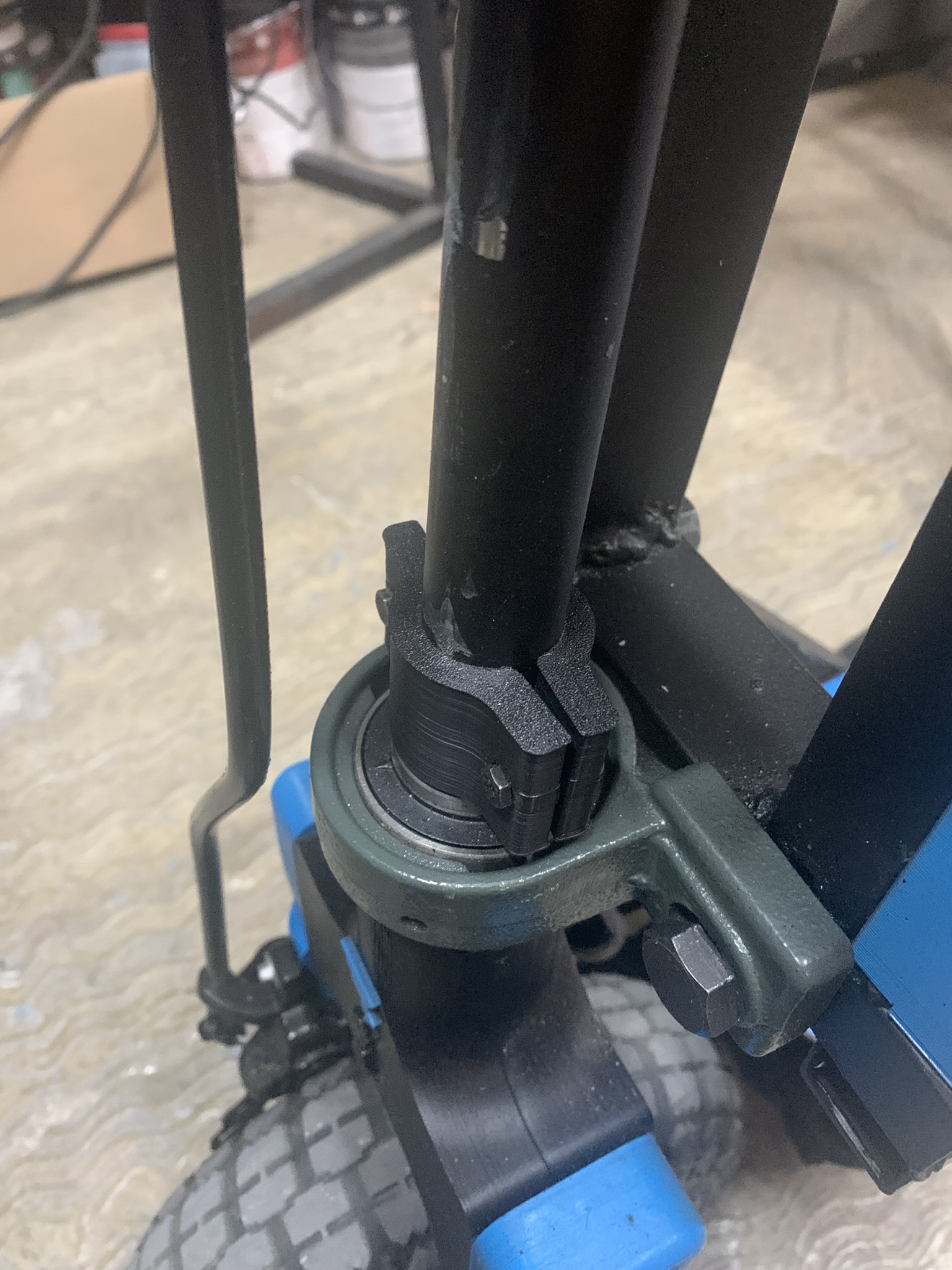
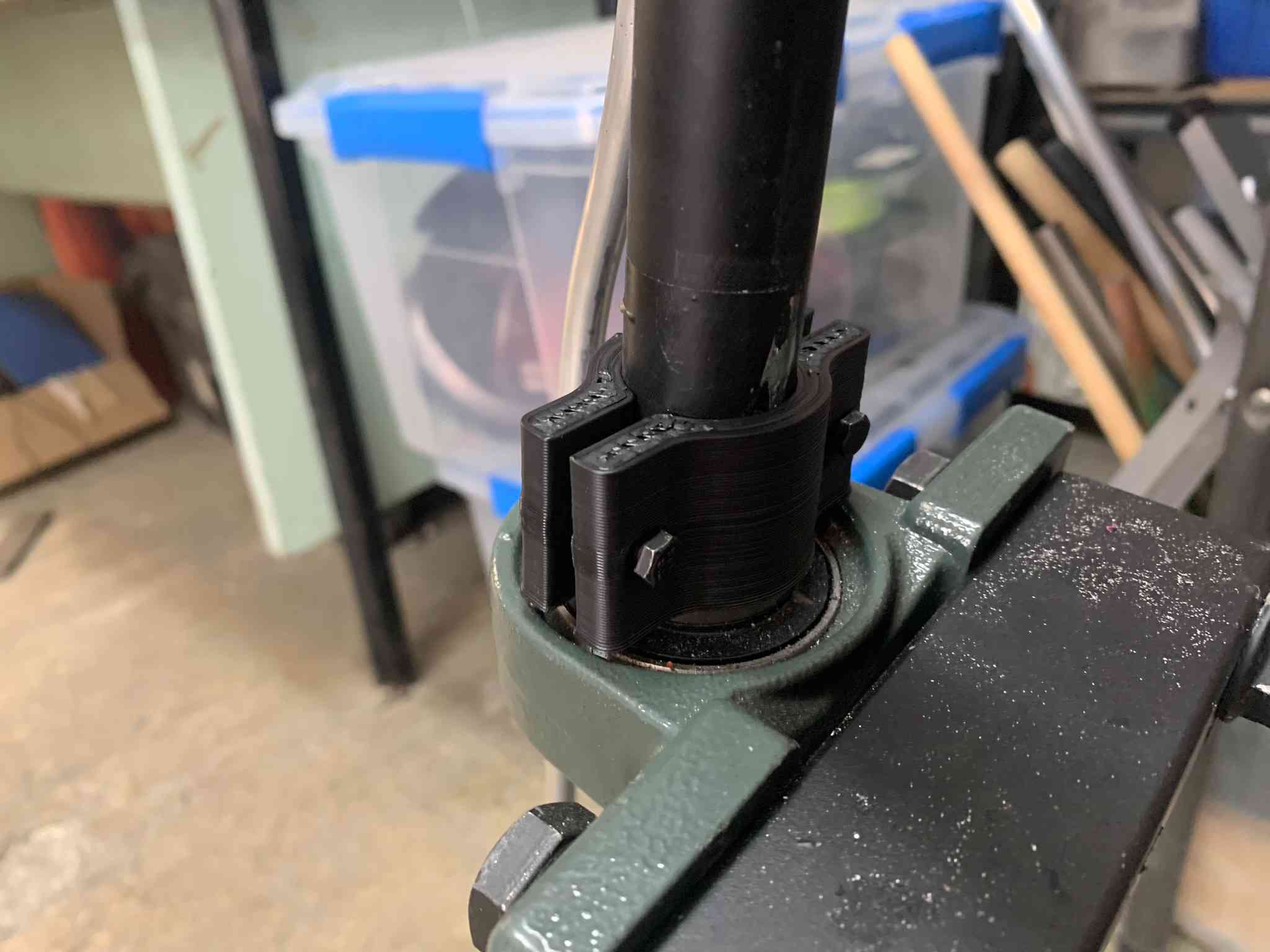
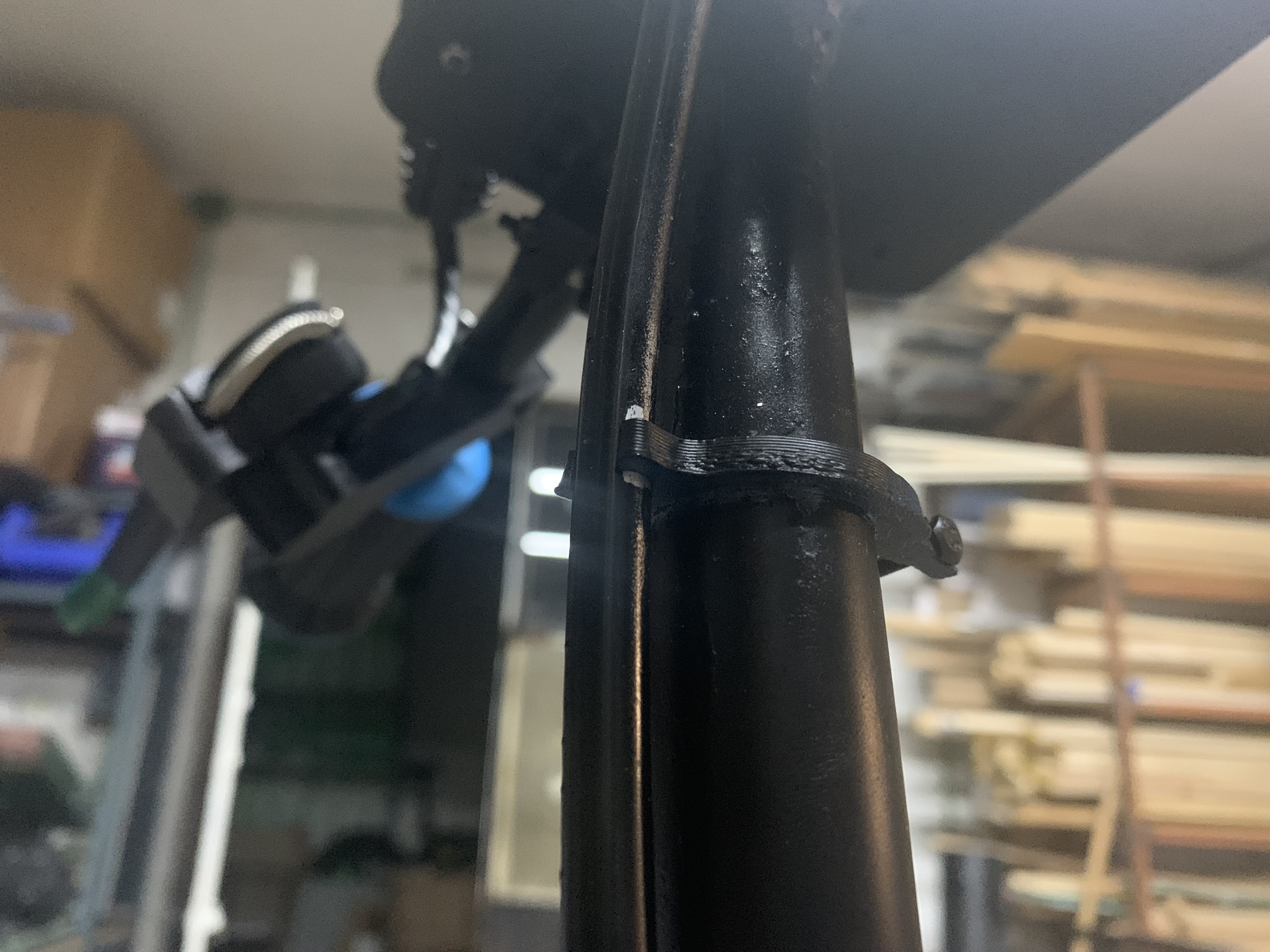
Then a 1" steel tube is inserted against the top slot inside the front wheel assembly, the tube is screwed onto the assembly using two M6x30 screws and passed through the front mounted rowlocks in the chassis. After this the tube is secured using two 3D printed clamps with screws.
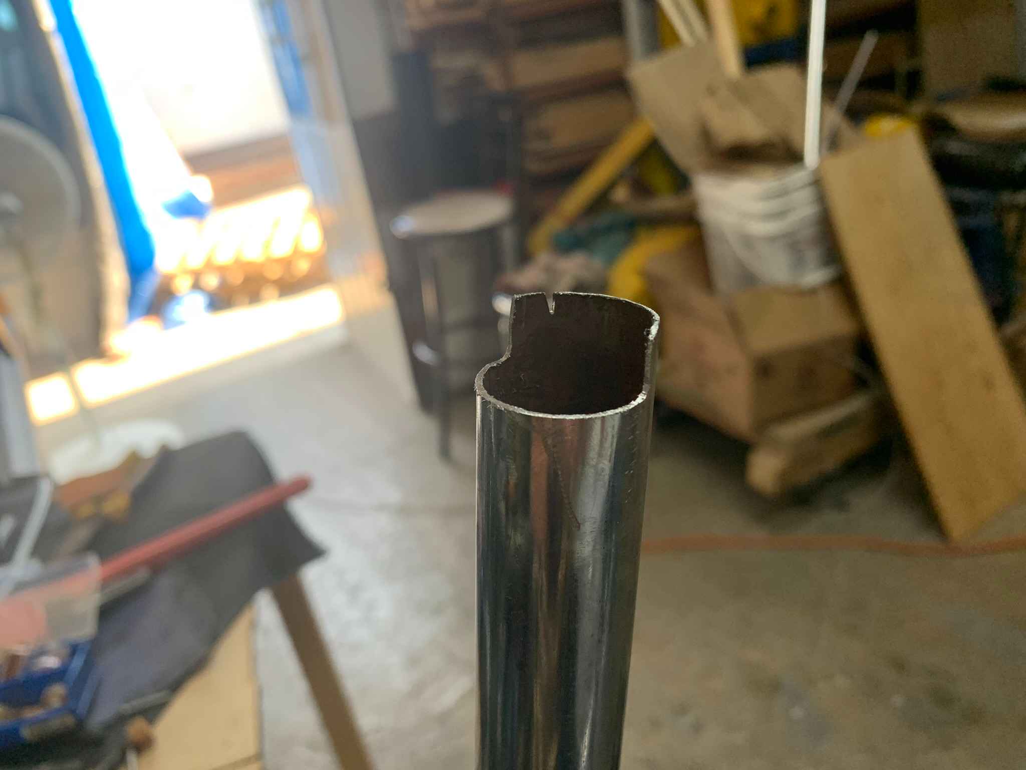
A small slot was cutted onto the tube to make place for the steel handle, which was then welded onto the vertical axle, the rubber handles are mounted here.
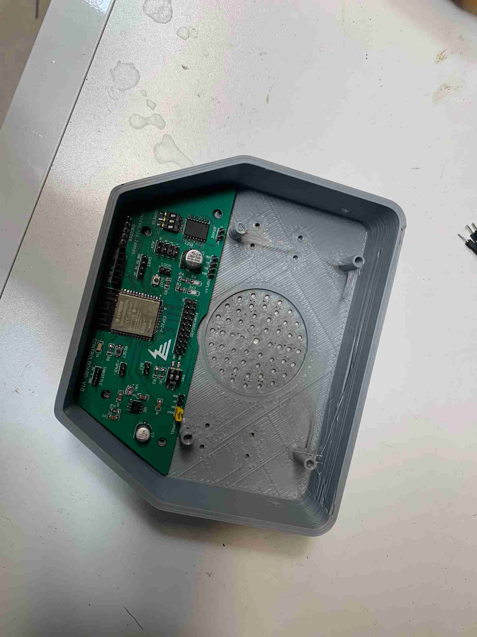
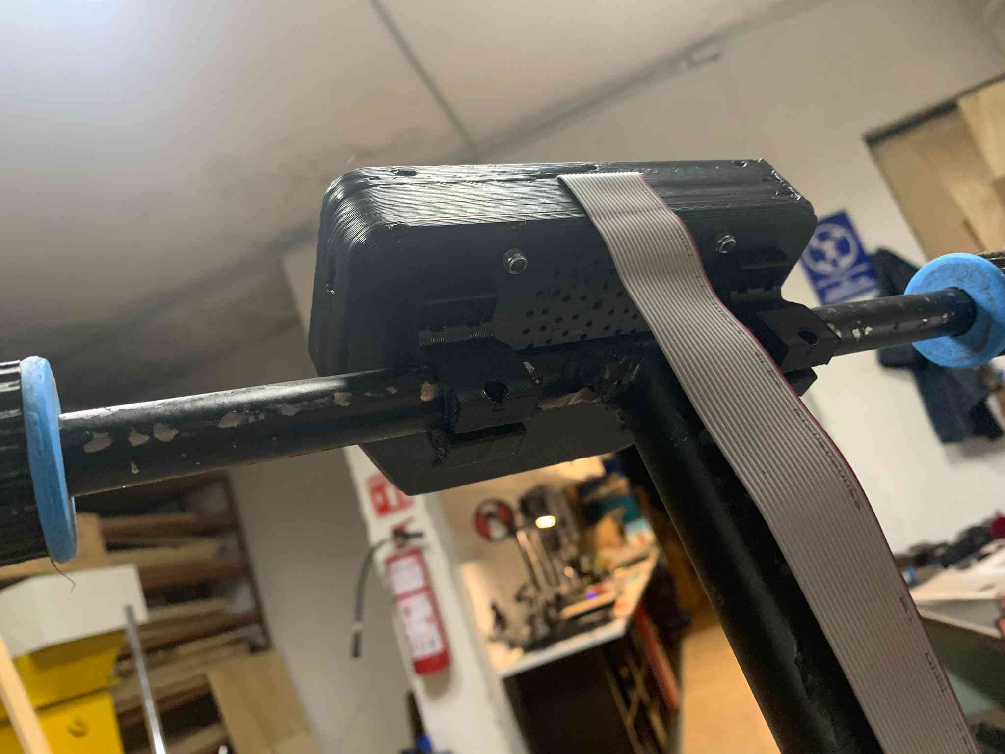
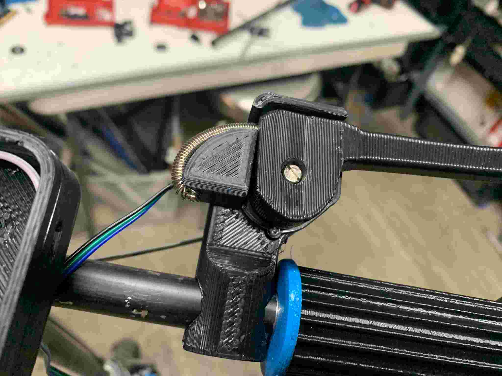
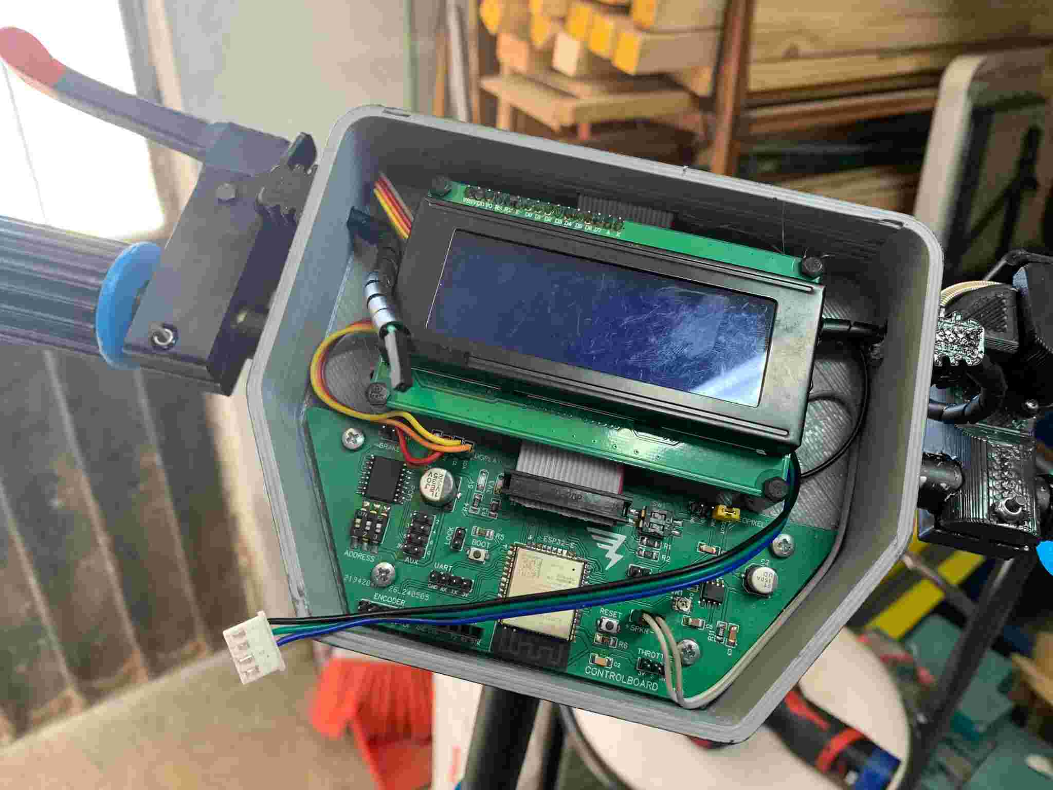
The instrument cluster had to be assembled next, using a 3D printed enclosure the previously assembled and soldered control PCB (See here) was mounted using some screws, and all the connections were made. The enclosure was itself mounted to the handle using some M3x10 screws against two 3D printed clamps.
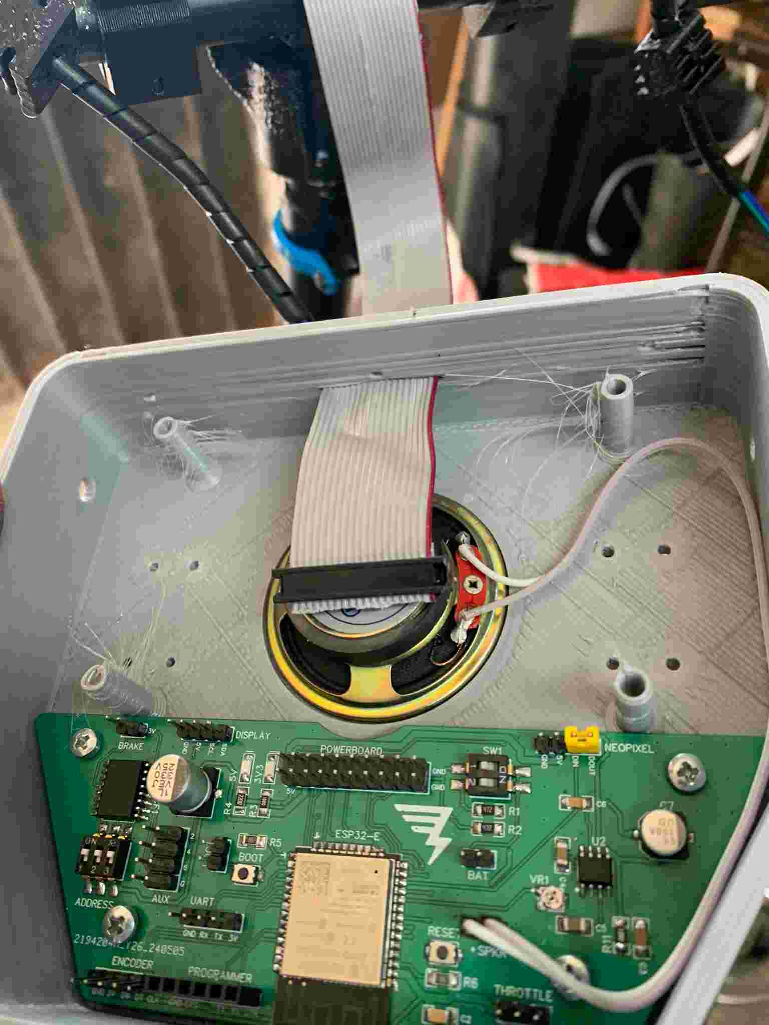
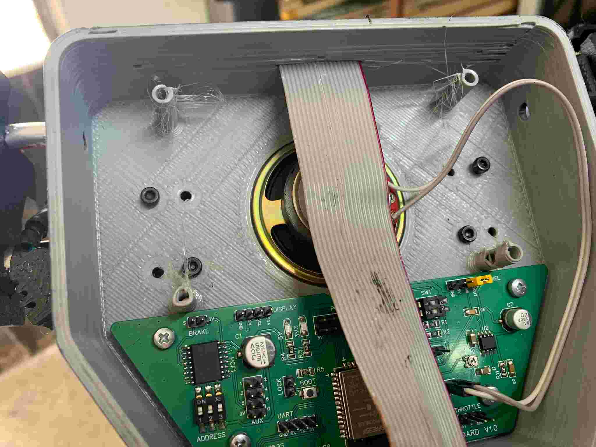
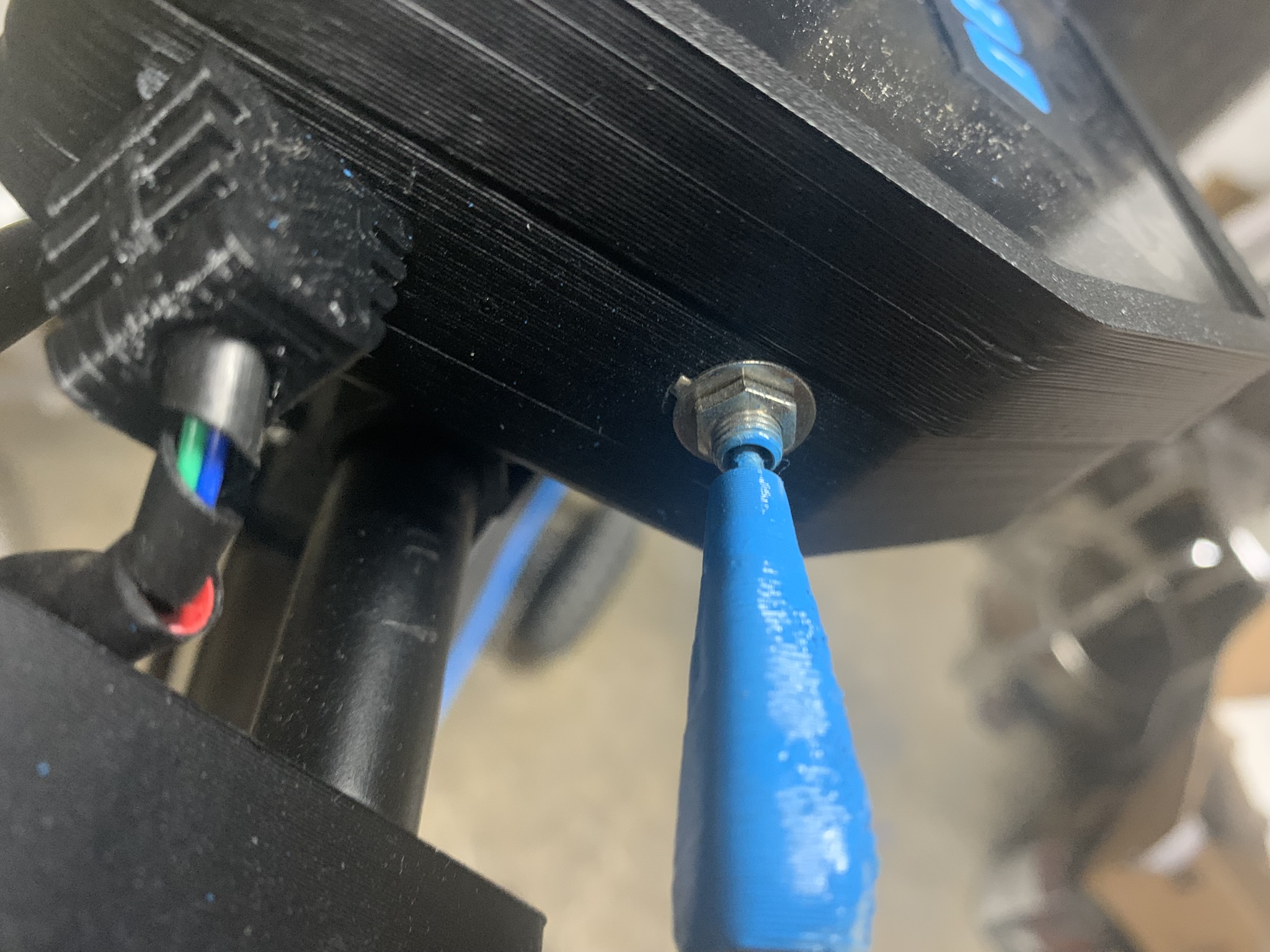
The 20-way flat cable that comes out of the instrument cluster, is concealed inside the steel tube, when it reaches the bottom, it is secured with an acrylic piece and two screws. Then, it is bridged onto the main chassis with a black cable organizer, it is important to give it some slack, in order to allow the front wheel to turn without braking the cable.
The brake and throttle lever assemblies were then put together:
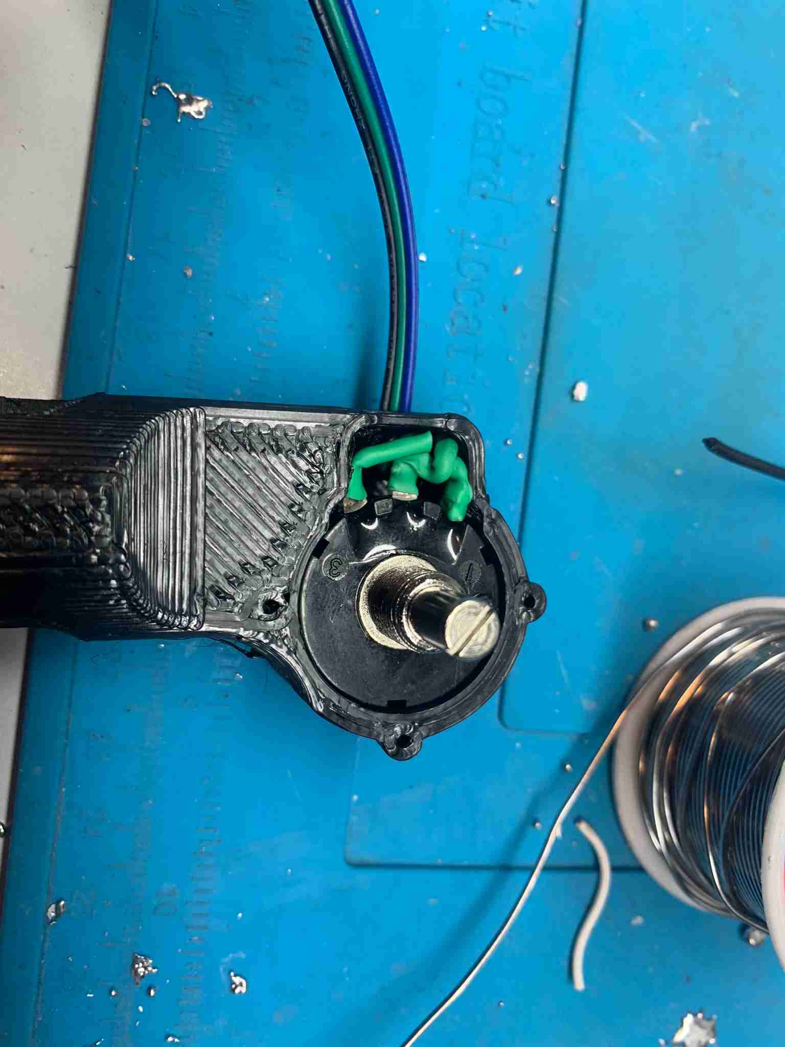
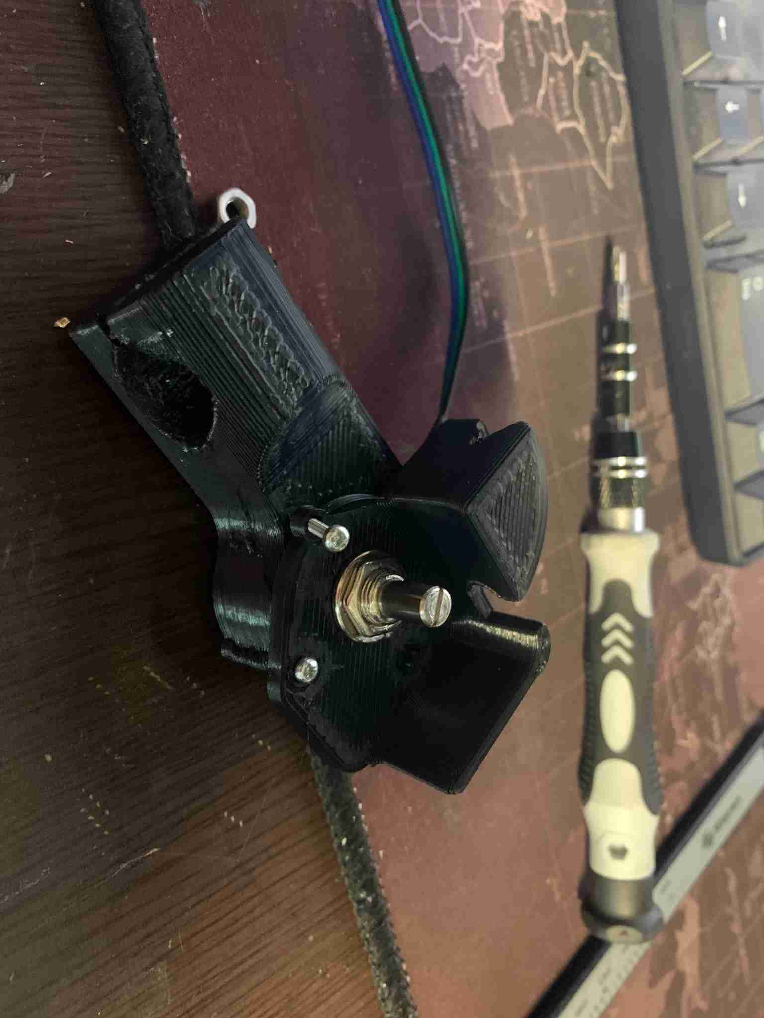
The throttle assembly requires a potentiometer to be placed inside it and measure the user's throttle input, also a spring mechanism is mounted to make the lever return automatically to its place:
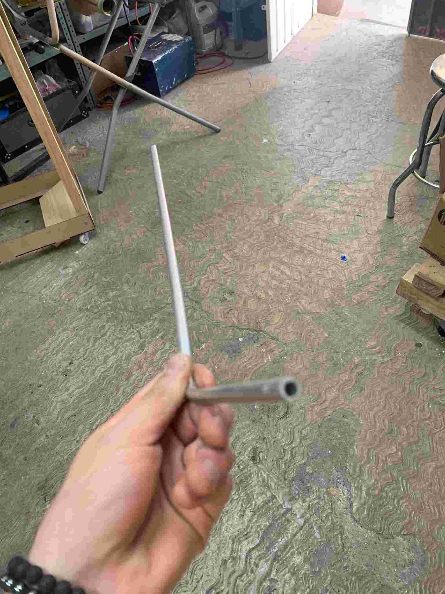
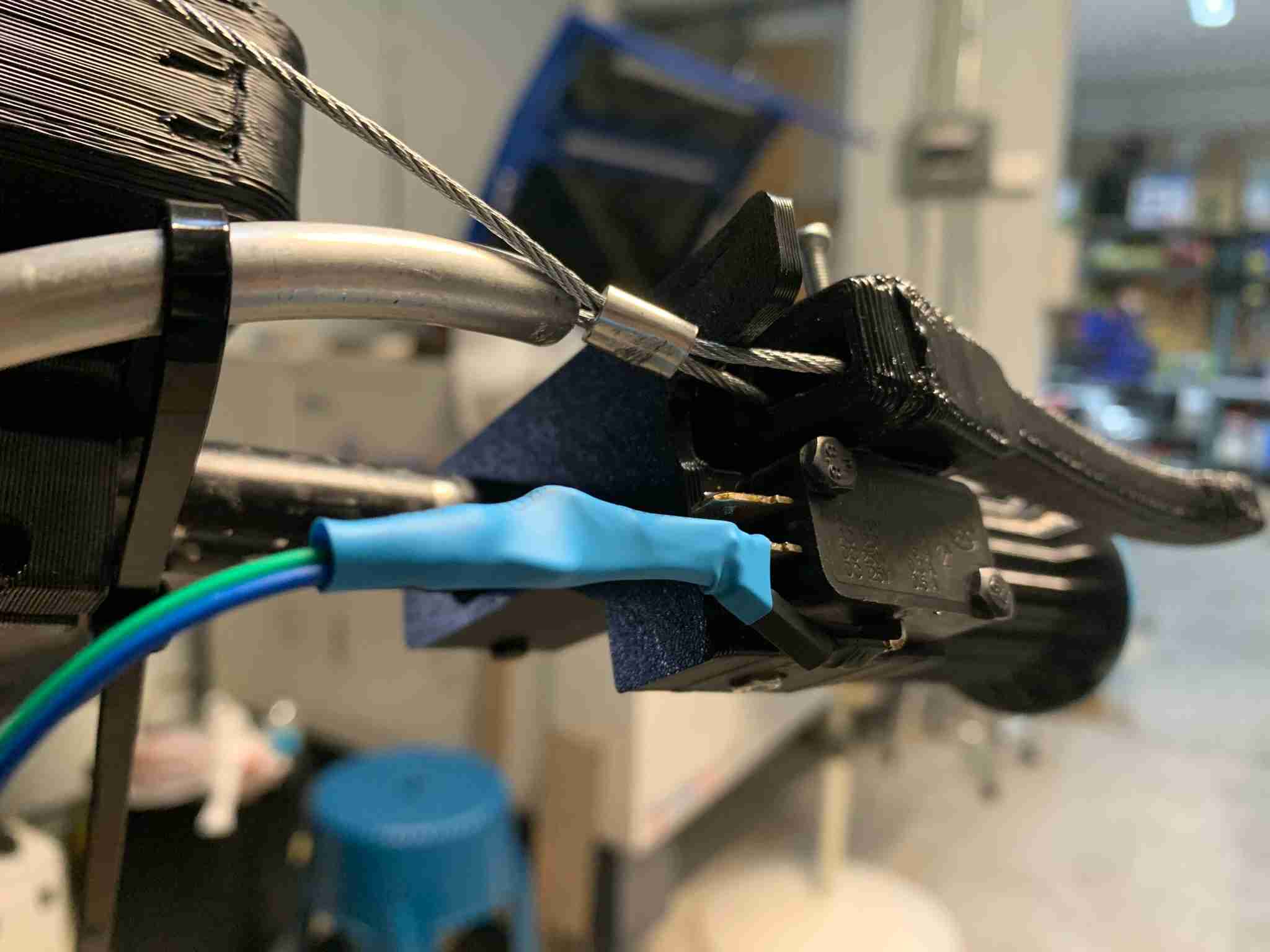
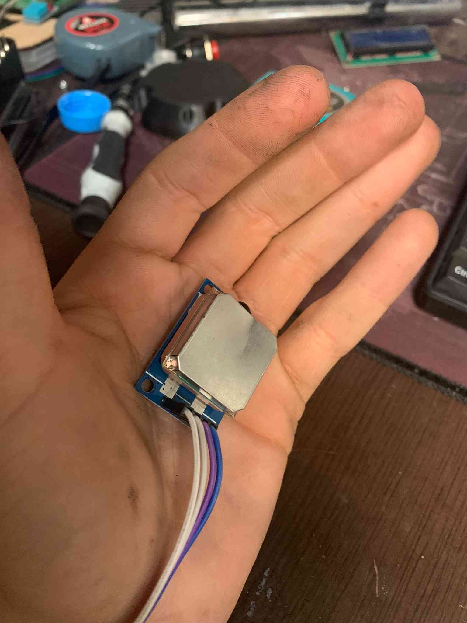
The brake line, which is purely mechanical, is assembled using a separate lever mechanism and a thin but strudy steel wire, the steel wire runs through an external aluminum tube from the brake lever down to the braking mechanism. The length of the wire has to be calibrated in order to obtain an adequate braking force from a reasonable pressing length of the brake lever. To control the braking lights and other safety measures inside the scooter's control board, the brake is tied with a limit switch, which at minimal pressing of the brakes, gets activated, sending a signal to the microcontroller.
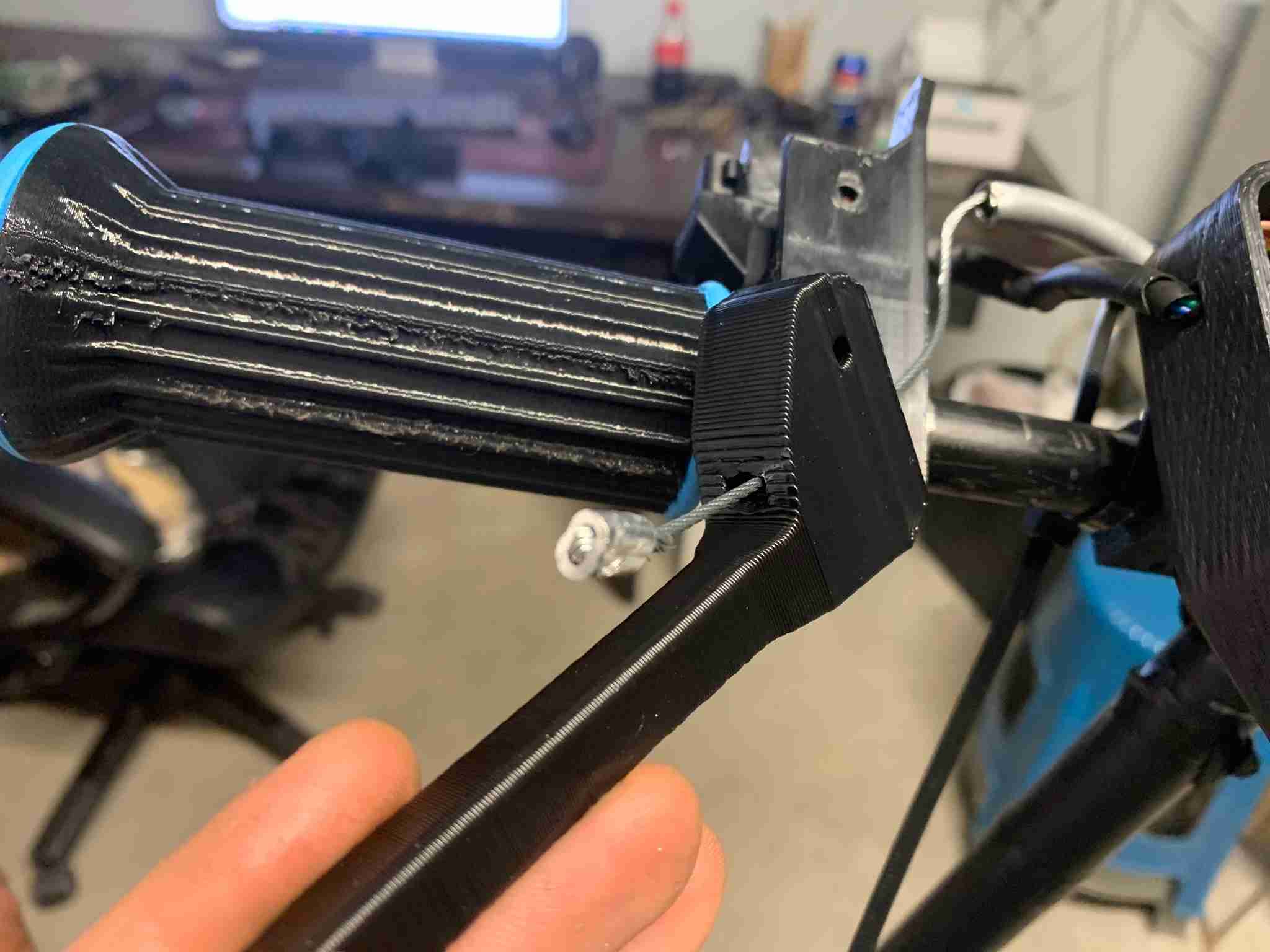
The brake line tube is secured against the drive axle using 3D printed pressure clamps. Decorative finishes are mounted onto the chassis and rowlock assemblies.
Now that everything is mounted, remaining new cables (brake and throttle) are connected to the control board via some dupont connectors, also, the GPS module is connected to its respective port.
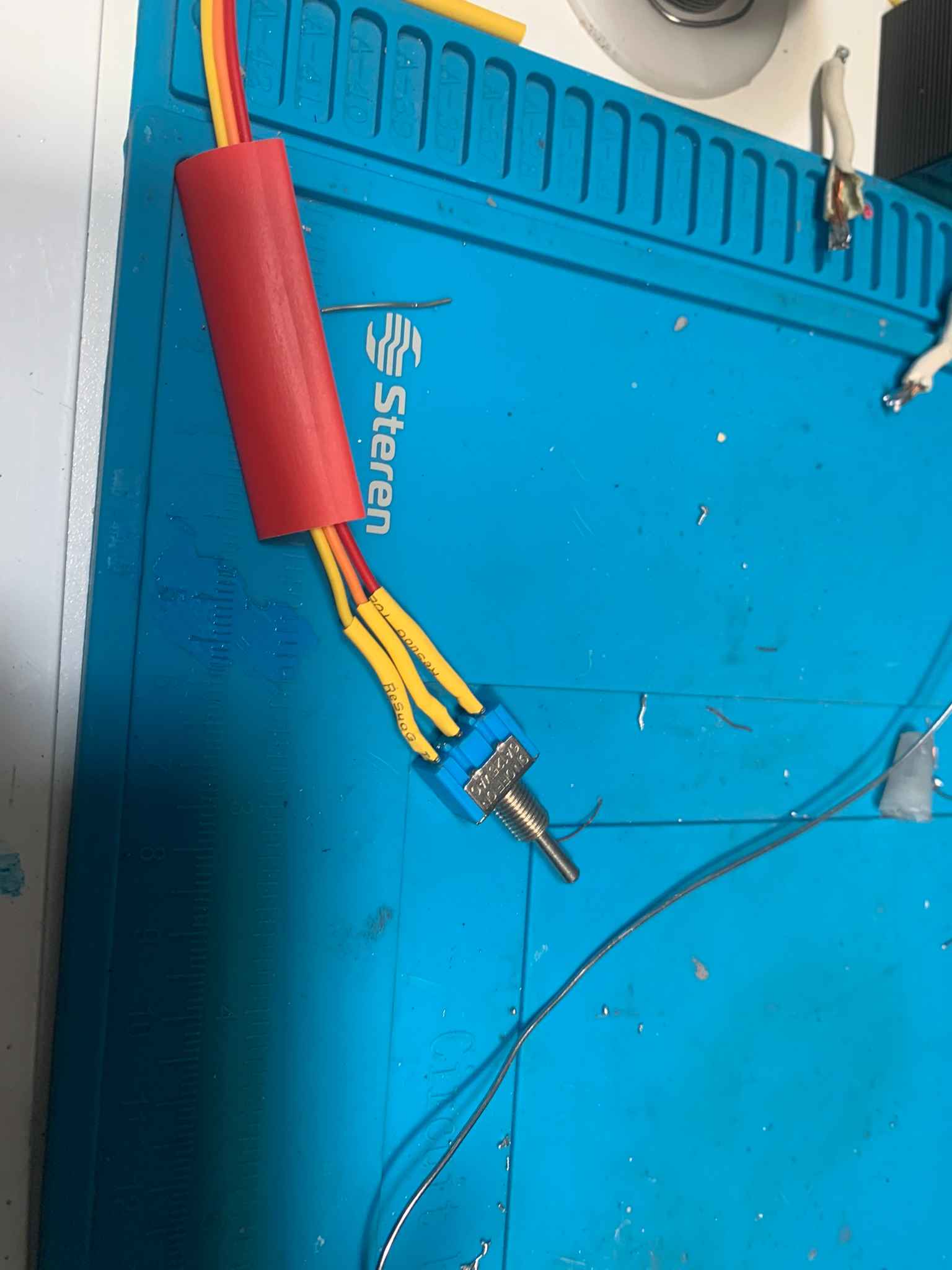
Then, the turn signal switch is mounted, not before soldering three wires to it. The switch is mounted on a side of the intrument cluster's casing. A decorative 3D printed lever is then glued to the switch.
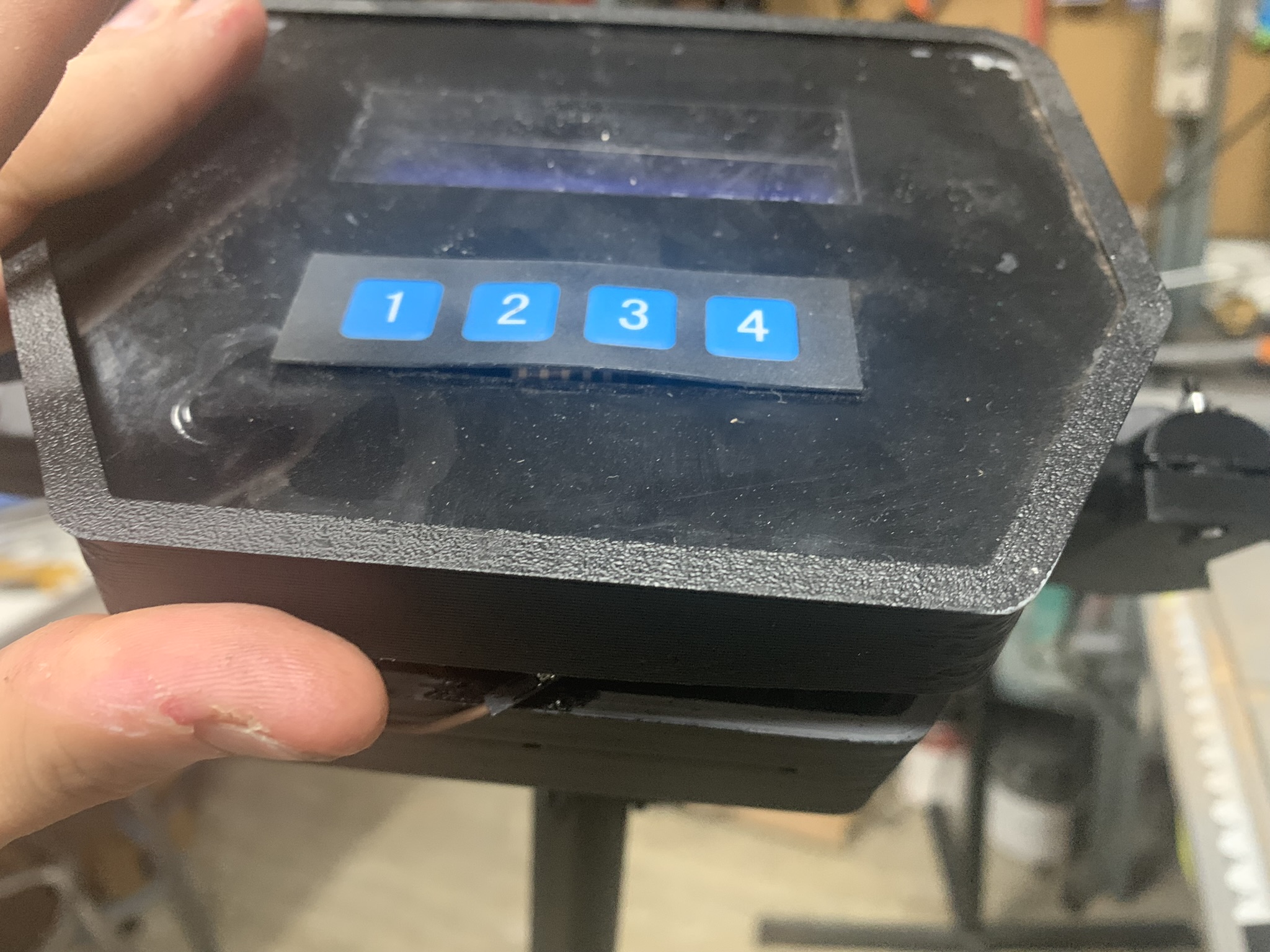
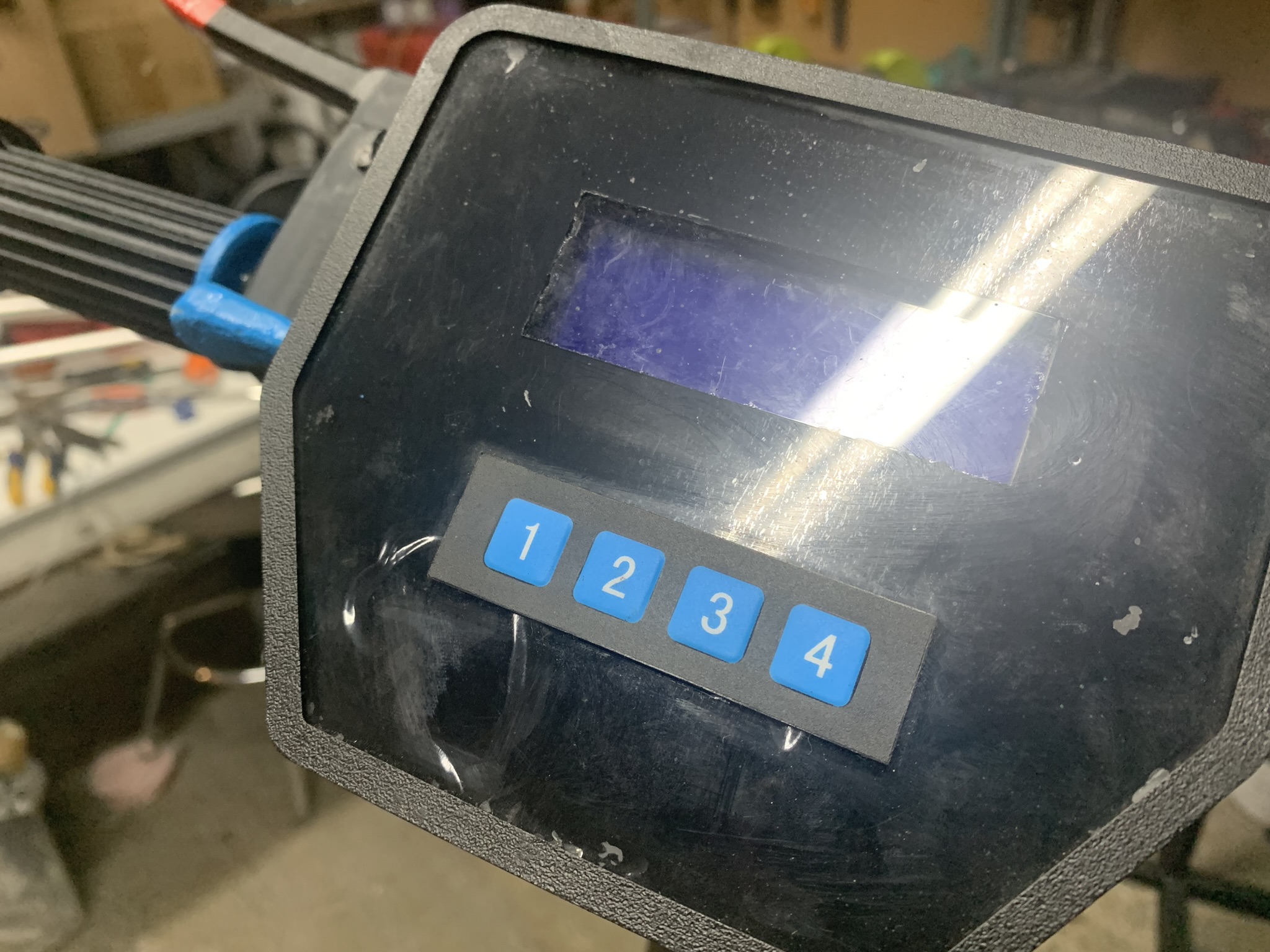
The last step, is to cover the dashboard and connect its buttons. Which is really simple and done with a black laser-cutted acrylic piece and the keyboard module which is mounted against the acrylic and connected internally with the board.
This is it for the Drivetrain design and assembly! See next page (Main Chassis Assembly)
Download all final proyect assets here!