Input devices
Linked to the group assigment page
Introduction
Digital inputs are connection points in electronic systems that receive binary signals to control internal devices or respond to environmental changes. These signals, which can be high or low, are fundamental in a wide range of technological applications.
Examples of Digital Inputs:
- Buttons to start or stop functions.
- Proximity sensors to detect nearby objects.
- Temperature sensors to monitor environmental changes.
- Switches to change device states.
- Light sensors to adjust lighting.
- Microphones to capture sounds.
- Security systems to activate alarms.
This week at Fab Academy, we will focus exclusively on integrating and experimenting with different types of sensors like the HC-SR04 ultrasonic sensor and mlx90614 sensor for my practical project.
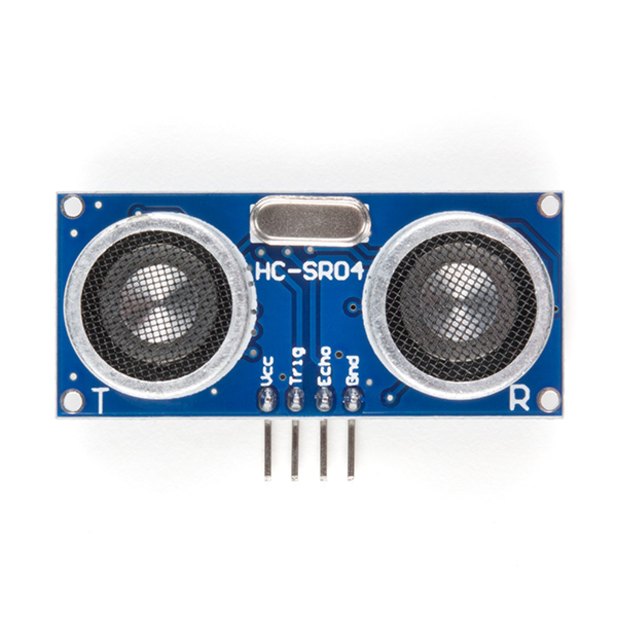
HC-SR04 Ultrasonic Sensor
The HC-SR04 ultrasonic sensor is a device that can measure the distance to an object by sending sound waves and receiving the reflected echo. It is widely used in robotics and automation systems for object detection and navigation.
One of the most notable features of the HC-SR04 is its ability to detect objects from 2 cm to 400 cm with high precision and reliability. Additionally, it is known for its ease of use and low cost, making it accessible to amateurs and professionals alike.
The HC-SR04 can be easily controlled using microcontrollers like Arduino, using digital input signals to initiate measurement and then receiving the distance information as a prolonged digital input.
In summary, the HC-SR04 sensor is a popular choice for electronic projects that require precise distance measurement in a compact and economical package. Its accuracy, versatility, and ease of use make it indispensable in many automation and robotics projects.
| Feature | Description |
|---|---|
| Model | HC-SR04 |
| Sensor Type | Ultrasonic |
| Operating Voltage | 5V DC |
| Operating Current | 15 mA |
| Detection Range | 2 cm to 400 cm |
| Accuracy | 3 mm |
| Weight | 9 g |
| Dimensions | 45 x 20 x 15 mm |
Pinout
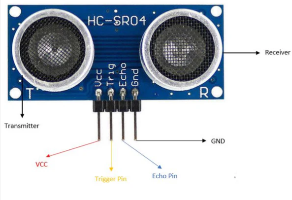
The HC-SR04 is an ultrasonic sensor that has four pins: VCC, Trig, Echo, and GND. Here is the typical description of the pins:
- VCC: This pin is connected to the power supply (5V). It provides power to the sensor for operation.
- Trig (Trigger): This pin is used to initiate the sensor to send out an ultrasonic burst. It is an input pin where a short 10 microsecond pulse is sent to start the measurement process.
- Echo: This pin outputs the signal corresponding to the reflection of the ultrasonic burst. It outputs a pulse that is proportional in duration to the distance to the detected object.
- GND (Ground): This pin is connected to the ground of the power supply. It completes the electrical circuit and provides a common voltage reference for the sensor's operation.
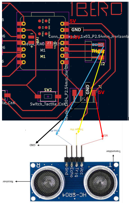
To connect the HC-SR04 ultrasonic sensor to a development board like the Xiao ESP32-C3, you need to properly connect the sensor's pins to the board. First, you supply power to the sensor by connecting the VCC pin of the HC-SR04 to the 5V power output of the Xiao ESP32-C3 and connect the ground (GND) pin to the board's ground.
The 'Trig' pin of the HC-SR04, which is used to initiate the measurement by sending out an ultrasonic burst, should be connected to one of the GPIO pins on the Xiao ESP32-C3 capable of delivering a digital high pulse. The 'Echo' pin, which receives the echo of the ultrasonic burst, should be connected to another GPIO pin capable of reading high/low input signals.
For example, on the Xiao ESP32-C3, you can connect the 'VCC' pin of the HC-SR04 to a 5V power pin, the 'GND' pin to a ground pin, the 'Trig' pin to a designated GPIO pin (e.g., GPIO6), and the 'Echo' pin to another GPIO pin (e.g., GPIO7). Then, you can use a program to trigger the 'Trig' pin with a 10 microsecond pulse and measure the duration of the high signal on the 'Echo' pin to calculate the distance to an object.
Below is the pinout guide of the Xiao ESP32-C3 to assist with the connections:
- 5V: Connect to HC-SR04 VCC.
- GND: Connect to HC-SR04 GND.
- GPI10 (or any digital output pin): Connect to HC-SR04 Trig.
- GPIO9 (or any digital input pin): Connect to HC-SR04 Echo.
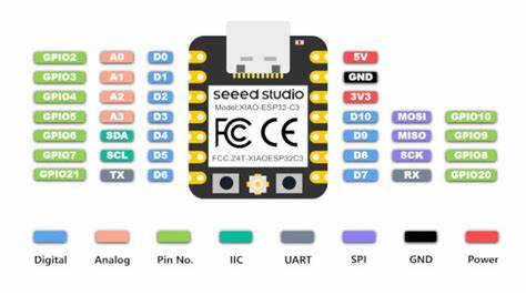
Recalling a bit from last week's board, we see that the available pins are D6, D7, D8, D9, and D10. Therefore, we will connect it to D9 and D10, although it can be any of them since all are GPIO pins. The others will be connected to the 5V and ground pins we left previously.
schedule outputs
We will install the Newping library
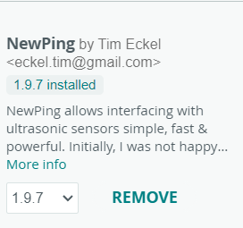
Overview of the NewPing Library
The NewPing library is designed to enhance the interaction with ultrasonic sensors such as the HC-SR04 for Arduino projects. Below are the key features and benefits:
- Echo Timing Efficiency: Uses non-blocking methods and timers for more accurate and faster echo timing management.
- Support for Multiple Sensors: Capable of handling multiple sensors simultaneously, ideal for projects requiring multiple measurements at the same time.
- CPU Optimization: Minimizes microcontroller downtime, allowing other tasks to be performed while processing sensor signals.
- Ease of Use: Provides a simple interface to start measurements and obtain results, simplifying the necessary code.
- Broad Compatibility: Compatible with various ultrasonic sensor models, though optimized for specific models like the HC-SR04.
In specific use with the HC-SR04 sensor, NewPing significantly simplifies the distance measuring process by automatically managing the pulse signal and echo reading, allowing more focus on project logic than on technical details of sensor handling.
Explanation
Ultrasonic Sensor Code Explanation
This code utilizes the NewPing library to interact with an ultrasonic sensor.
Three constants are defined using #define:
- TRIGGER_PIN: The GPIO pin used for the Trigger pin of the ultrasonic sensor. In this case, it's defined as D9.
- ECHO_PIN: The GPIO pin used for the Echo pin of the ultrasonic sensor. It's defined as D10.
- MAX_DISTANCE: The maximum distance that the sensor is capable of measuring in centimeters. It's set to 200 cm, but you can adjust it according to your needs.
An object sonar of the NewPing class is then initialized using the defined pins and maximum distance.
In the setup() function, serial communication is initialized at a baud rate of 115200 using Serial.begin(115200).
The loop() function is the core of the program and is executed repeatedly. First, a delay of 100 milliseconds is introduced using delay(100). This ensures that there is an interval between each measurement to avoid excessively frequent measurements.
Then, the ping_cm() method of the sonar object is called to perform a distance measurement in centimeters. The distance value is stored in the distance variable, which is of type unsigned int.
Next, it checks if the measured distance is equal to zero. If so, it means that the sensor couldn't detect any object within its measurement range, and "Out of range" is printed to the serial console.
If the measured distance is not zero, it prints the measured distance in centimeters using Serial.print() and Serial.println().
This cycle repeats continuously, allowing the program to measure and display the distance detected by the ultrasonic sensor in real-time.
This code will make the servo connected to GPIO pin 9 of the ESP32 move from 0 to 180 degrees in a continuous loop, with a 1-second pause between each movement. Make sure to correctly connect the servo and power it with the appropriate power source.
		  #include <NewPing.h>

		  // Definition of pins and maximum distance
		  #define TRIGGER_PIN  D9
		  #define ECHO_PIN     D10
		  #define MAX_DISTANCE 200

		  NewPing sonar(TRIGGER_PIN, ECHO_PIN, MAX_DISTANCE);

		  void setup() {
			Serial.begin(115200);
		  }

		  void loop() {
			delay(100);
			unsigned int distance = sonar.ping_cm();

			if (distance == 0) {
			  Serial.println("Out of range");
			} else {
			  Serial.print("Distance: ");
			  Serial.print(distance);
			  Serial.println(" cm");
			}
		  }
Now that we know how to program an ultrasonic sensor, I will implement it as a dog feeder measurement sensor that will be complementary to my final project delivery. This code will have a maximum value of 30 cm and a minimum of 5 cm.
Explanation
The code utilizes an ultrasonic sensor to measure the distance and determine the fill level of a pet food container.
First, the NewPing library is imported, which provides functions to interact with the ultrasonic sensor.
Then, several important constants are defined:
- TRIGGER_PIN and ECHO_PIN represent the GPIO pins used to connect the ultrasonic sensor.
- MAX_DISTANCE is the maximum distance that the sensor can measure, defined in centimeters.
- MIN_DISTANCE is the minimum distance when the container is full, which can be adjusted according to user needs.
- LEVEL_RANGE calculates the range of possible levels in the container.
An object 'sonar' of the NewPing class is initialized with the specified pins and maximum distance.
In the setup() function, serial communication is initiated at a baud rate of 115200.
The loop() function is the core of the program and is executed repeatedly:
- A delay of 1900 milliseconds (1.9 seconds) is introduced between each measurement to avoid excessively frequent measurements.
- The ping_cm() method of the sonar object is used to measure the distance in centimeters.
- It is checked whether the measured distance is equal to zero or greater than the specified maximum distance. If either of these conditions is true (using the || operator), the code block inside the if statement is executed. This results in printing the message "Out of range" to the serial console.
- If the measured distance is within the valid range, the relative fill level of the pet food container is calculated using the map() function. Then, this fill level is printed to the serial console.
This cycle repeats continuously, allowing the program to measure and display the fill level of the pet food container in real-time.
 #include <NewPing.h>

 // Definition of pins and maximum distance
 #define TRIGGER_PIN  D9   // GPIO pin for sensor Trigger pin
 #define ECHO_PIN     D10   // GPIO pin for sensor Echo pin
 #define MAX_DISTANCE 30 // Maximum distance to measure in centimeters
 #define MIN_DISTANCE 5   // Minimum distance when the container is full (adjust according to your needs)
 #define LEVEL_RANGE  (MAX_DISTANCE - MIN_DISTANCE) // Range of levels

 NewPing sonar(TRIGGER_PIN, ECHO_PIN, MAX_DISTANCE); // Sensor initialization

 void setup() {
 Serial.begin(115200); // Serial communication initialization
		  }

void loop() {
delay(1900); // Wait one second between measurements

unsigned int distance = sonar.ping_cm(); // Measure distance in centimeters

if (distance == 0 || distance > MAX_DISTANCE) {
Serial.println("Out of range"); // If the distance is 0 or greater than the maximum distance, indicate it's out of range
}
else
{
 // Calculate relative fill level based on the measured distance
int level = map(distance, MIN_DISTANCE, MAX_DISTANCE, 100, 0); // Map distance to a fill percentage
Serial.print("Kibble level: ");
Serial.print(level);
Serial.println("%"); // Print kibble level
			}
		  }
MLX90614 Infrared Temperature Sensor
The MLX90614 is an infrared temperature sensor capable of non-contact temperature measurements. It is commonly used in various applications such as medical equipment, industrial systems, and consumer electronics.
One of the standout features of the MLX90614 is its ability to measure temperatures from -70°C to +380°C with a high degree of accuracy and without direct contact with the object being measured. This makes it particularly useful for health monitoring applications where non-invasive methods are preferred. Additionally, its low cost and ease of integration with microcontrollers like Arduino make it accessible for both amateurs and professionals.
The sensor operates by detecting the infrared energy emitted by objects and converting it into an electrical signal that represents the temperature. This allows for quick and reliable temperature readings, making it an indispensable tool in many automated systems and electronic projects.
In summary, the MLX90614 sensor is highly valued for its precision, versatility, and non-contact approach to temperature measurement, making it essential in a wide range of applications.
| Feature | Description |
|---|---|
| Model | MLX90614 |
| Sensor Type | Infrared Temperature |
| Operating Voltage | 3.3V to 5V DC |
| Operating Current | 1.5 mA |
| Temperature Range | -70°C to +380°C |
| Accuracy | ±0.5°C |
| Weight | 4.9 g |
| Dimensions | Various (dependent on package) |
Pinout
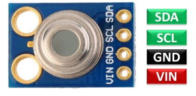
The MLX90614 is an infrared temperature sensor that typically has two main pins: VCC and GND, along with data communication pins, SDA (Serial Data) and SCL (Serial Clock). Here is the typical description of the pins:
- VCC: This pin is connected to the power supply (3.3V to 5V). It provides power to the sensor for operation.
- GND (Ground): This pin is connected to the ground of the power supply. It completes the electrical circuit and provides a common voltage reference for the sensor's operation.
- SDA (Serial Data): This pin is used for data communication between the sensor and a microcontroller via the I2C protocol. It transmits the temperature data read by the sensor.
- SCL (Serial Clock): This pin is used to provide the clock signal for the I2C communication protocol, controlling the timing of the data transmission.
To connect the MLX90614 infrared temperature sensor to a development board like the Xiao ESP32-C3, you need to properly connect the sensor's pins to the board. First, you supply power to the sensor by connecting the VCC pin of the MLX90614 to a 3.3V or 5V power output of the Xiao ESP32-C3 and connect the ground (GND) pin to the board's ground.
The 'SDA' pin of the MLX90614, which is used for serial data communication via the I2C protocol, should be connected to one of the I2C-capable GPIO pins on the Xiao ESP32-C3. Similarly, the 'SCL' pin, which is used for the serial clock signal, should be connected to another I2C-capable GPIO pin.
For example, on the Xiao ESP32-C3, you can connect the 'VCC' pin of the MLX90614 to a 3.3V power pin, the 'GND' pin to a ground pin, the 'SDA' pin to GPIO6 (or any I2C-capable pin), and the 'SCL' pin to GPIO7 (or any I2C-capable pin). Then, you can use a program to communicate with the MLX90614 using the I2C protocol to retrieve temperature readings.
Below is the pinout guide of the Xiao ESP32-C3 to assist with the connections:
- 3.3V: Connect to MLX90614 VCC.
- GND: Connect to MLX90614 GND.
- GPIO4 (or any I2C-capable pin): Connect to MLX90614 SDA.
- GPIO5 (or any I2C-capable pin): Connect to MLX90614 SCL.

schedule outputs
We will install the Adafruit MLX90614 library

Overview of the Adafruit MLX90614 Library
The Adafruit MLX90614 Library is specifically designed to facilitate the integration of the MLX90614 infrared temperature sensor in Arduino projects. Below are the key features and benefits:
- Easy Integration: Simplifies the code necessary for initializing and reading temperatures from the MLX90614 sensor, making it more accessible to both beginners and experienced developers.
- High Precision Handling: Provides built-in functions to accurately manage the temperature readings from the sensor, ensuring reliable data collection.
- Efficient Communication: Utilizes the I2C communication protocol effectively to minimize the overhead and speed up sensor data retrieval.
- Multiple Device Capability: Supports handling of multiple MLX90614 sensors over the same I2C bus, ideal for complex projects that require readings from multiple points.
- Extensive Documentation: Comes with detailed documentation and examples, which help in quick setup and troubleshooting, facilitating a smoother development process.
When used with the MLX90614 sensor, the Adafruit library streamlines the process of temperature measurement by automatically managing the intricacies of I2C communication and data conversion, allowing developers to focus more on the application logic than on the technicalities of sensor integration.
Explanation
This document provides a detailed explanation of the Arduino sketch used for interfacing with the MLX90614 sensor.
Code Breakdown
- #include <Wire.h>: Includes the Wire library, which is used for I2C communication. It is necessary for the Adafruit MLX90614 library to communicate with the sensor via the I2C bus.
- #include <Adafruit_MLX90614.h>: Includes the Adafruit MLX90614 library that provides the necessary functions to interact with the MLX90614 sensor.
- Adafruit_MLX90614 mlx = Adafruit_MLX90614();: Creates an instance of the mlx object for the MLX90614 sensor. This is required to access the functions provided by the Adafruit library, such as reading the temperature.
- void setup() {: Defines the setup function, which only runs once at the start of the program. This function sets up initial conditions.
- Serial.begin(115200);: Initializes serial communication at 115200 baud, which allows for data transmission between the microcontroller and the computer.
- while (!Serial);: Waits for the serial connection to become available. Useful for boards that require a serial connection to upload programs, like some versions of Arduino Leonardo.
- Serial.println("Iniciando test del MLX90614");: Sends a message via the serial port indicating the start of the sensor test.
- if (!mlx.begin()) {: Tries to initialize the MLX90614 sensor. If mlx.begin() returns false, it means there was a problem attempting to start the sensor.
- Serial.println("Error al iniciar el sensor MLX90614");: If initialization fails, it prints an error message.
- while (1);: Creates an infinite loop that stops program execution if the sensor could not be initiated.
- void loop() {: Defines the loop function, which runs repeatedly after setup.
- float objectTemp = mlx.readObjectTempC();: Reads the temperature of the object detected by the sensor in Celsius and stores the value in objectTemp.
- if (isnan(objectTemp)) {: Checks if the read value is a valid number. isnan is a function that checks if a number is 'Not a Number'.
- Serial.println("Error al leer las temperaturas");: If the number is not valid, it prints an error message.
- Else: If the number is valid, executes the following block of code.
- Serial.print("Temperatura del Objeto= ");: Prints a text string introducing the temperature value.
- Serial.print(objectTemp);: Prints the temperature of the object.
- Serial.println(" °C");: Adds " °C" at the end of the line and prints a line break.
- Serial.println();: Prints an additional line break to separate the readings in the serial output.
- delay(1000);: Pauses the program execution for 1000 milliseconds (1 second), which reduces the frequency of the readings.
	// Include the necessary libraries for I2C communication and for handling the MLX90614 sensor
		  #include <Wire.h>
		  #include <Adafruit_MLX90614.h>

		  // Create an object for the MLX90614 sensor
		  Adafruit_MLX90614 mlx = Adafruit_MLX90614();

		  // Initial program setup
		  void setup() {
			// Start serial communication with the computer for debugging
			Serial.begin(115200);
			// Wait for serial connection to be ready to send data
			while (!Serial);

			// Inform via serial that the MLX90614 sensor test is starting
			Serial.println("Starting MLX90614 sensor test");

			// Start the MLX90614 sensor and check for any initialization errors
			if (!mlx.begin()) {
			  // If there's an initialization error, send an error message via serial
			  Serial.println("Error initializing MLX90614 sensor");
			  // Enter an infinite loop to halt further program execution
			  while (1);
			}
		  }

		  // Main program loop, executed repeatedly
		  void loop() {
			// Read the temperature of the object pointed by the sensor in Celsius degrees
			float objectTemp = mlx.readObjectTempC();

			// Check if the temperature value is valid
			if (isnan(objectTemp)) {
			  // If the value is not valid, print an error message via serial
			  Serial.println("Error reading temperatures");
			} else {
			  // If the value is valid, print the temperature via serial
			  Serial.print("Object Temperature= ");
			  Serial.print(objectTemp);
			  Serial.println(" °C");
			}

			// Print a newline to separate readings
			Serial.println();
			// Wait one second before the next reading
			delay(1000);
		  }