Output devices
Linked to the group assigment page
introduccion
Digital outputs are connection points in electronic systems that emit binary signals to control external devices. These signals, which can be on/off or high/low, are fundamental in a wide range of technological applications.
Examples of Digital Outputs:
- Indicator LEDs to display states.
- Electric motors to control movement.
- Relays to switch on higher power devices.
- Printers to manage printing.
- Speakers/buzzers to produce sounds.
- Displays to show visual information.
- Security systems to trigger alarms and sensors.
This week in Fab Academy, we will focus on integrating OLED displays, servos, and speakers. In my case, I will opt to combine buttons, LEDs, and a servo for my practical project.
servo motor
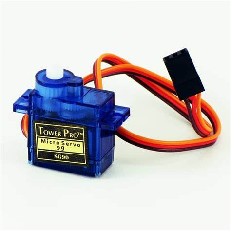
The SG90 motor is a type of low-cost and compact-sized servo motor. It is designed to provide precise control of angular motion, making it ideal for applications where a specific shaft position is required. This servo motor consists of a DC motor, a set of gears, and an integrated control circuit.
One of the most prominent features of the SG90 motor is its ability to rotate at an angle of up to 180 degrees, allowing for a wide range of movements. Additionally, the SG90 is known for its accuracy and stability in position, making it suitable for applications that require fine control of movement.
The SG90 motor can be easily controlled using pulse width modulation (PWM) signals generated by microcontrollers such as Arduino, Raspberry Pi, and other electronic devices. This allows users to precisely and flexibly control the position and speed of the servo motor.
In summary, the SG90 motor is a popular choice for electronic projects that require precise and reliable motion control in a compact and affordable package. Its ease of use, accuracy, and versatility make it a popular choice among hobbyists and manufacturers alike.
| Characteristic | Description |
|---|---|
| Model | SG90 |
| Motor Type | Servo motor |
| Operating Voltage | 4.8V - 6.0V |
| Operating Current | 0.1 - 0.5A |
| No-load Speed | 0.12 sec/60° (4.8V), 0.10 sec/60° (6.0V) |
| Stall Torque | 1.8 kg·cm (4.8V), 2.2 kg·cm (6.0V) |
| Weight | 9 g |
| Load Capacity | 1 to 2 kg (depending on application and conditions) |
| Dimensions | 23 x 12.2 x 29 mm |
pin out
The SG90 motor is a servo motor that has three wires: one red, one brown (or black), and one orange (or yellow). Here is the typical description of the pins:
- Red (+5V): This wire is connected to the 5-volt power supply (VCC) to provide power to the motor and the internal circuit.
- Brown or Black (GND): This wire is connected to ground (GND) to complete the electrical circuit and provide a common voltage reference.
- Orange or Yellow (Control Signal): This wire carries the servo's control signal. This control signal is a pulse width modulation (PWM) signal that determines the motor shaft's position. The pulse duration determines the servo's position. Typically, a 1 ms pulse represents the minimum position, a 1.5 ms pulse represents the center position, and a 2 ms pulse represents the maximum position.
- Precise Control: Allows for detailed and accurate positioning of servo motors.
- PWM Compatibility: Utilizes the ESP32's PWM channels to provide control signals to the servos, enabling better management of multiple servos simultaneously.
- Easy Integration: The library integrates seamlessly with the Arduino development environment for ESP32, simplifying programming and reducing development time.
- Flexible Configuration: Supports various servo motor configurations, allowing adjustments of angle limits and speed specifications as per project requirements.
- Resource Optimization: Optimizes the use of ESP32 resources, ensuring that the microcontroller's performance is not compromised while controlling one or more servo motors.
- #include <ESP32Servo.h>: This line includes the ESP32Servo.h library that we need to control the servo.
- Servo myservo: Here, we create an object named myservo of the Servo class. This object will allow us to control the servo.
- void setup(): This function runs once at the beginning of the program. This is where we set up the pin to which the servo is connected.
- myservo.attach(9): With this line, we're telling the program that the servo is connected to GPIO pin 9 of the ESP32.
- void loop(): This function runs in a continuous loop after the setup() function. This is where we specify what actions the program should perform repeatedly.
- myservo.write(0): With this line, we're moving the servo to the 0-degree position.
- delay(1000): This function makes the program wait for 1000 milliseconds (1 second) before continuing to the next instruction.
- myservo.write(180): With this line, we're moving the servo to the 180-degree position.
- delay(1000): Once again, we're making the program wait for 1 second before repeating the process.
- Download CODE 1 basic servo
- #include <ESP32Servo.h>: This line includes the ESP32Servo.h library, which allows us to control the servo from the ESP32.
- Servo myservo;: Here, we declare an object of type Servo named myservo, which we will use to control the servo.
- #define: Here, we define constants for the button pins and the LED pins.
- int button_0_state = 0;, int button_1_state = 0;, int servo_position = 0;: These variables are used to store the state of the buttons and the current position of the servo.
- void setup(): This function runs once at the start of the program and is responsible for setting up the pins.
- pinMode(BUTTON_0_PIN, INPUT_PULLUP);, pinMode(BUTTON_1_PIN, INPUT_PULLUP);, pinMode(LED_PIN_2, OUTPUT);, pinMode(LED_PIN_3, OUTPUT);, pinMode(LED_PIN_4, OUTPUT);: Here, we configure the pins as inputs (with internal pull-up) for the buttons and as outputs for the LEDs.
- void loop(): This function runs in a continuous loop and contains the main code of the program.
- digitalRead(BUTTON_0_PIN), digitalRead(BUTTON_1_PIN): These lines read the state of the buttons.
- myservo.write(): This function moves the servo to a specific position (0, 90, or 180 degrees).
- delay(100): These lines introduce a brief pause to debounce the button.
- while (digitalRead(BUTTON_0_PIN) == LOW) {}, while (digitalRead(BUTTON_1_PIN) == LOW) {}: These loops wait for the buttons to be released before continuing with the code.
- digitalWrite(LED_PIN_2, HIGH), digitalWrite(LED_PIN_3, HIGH), digitalWrite(LED_PIN_4, HIGH): These lines turn on the LEDs.
- digitalWrite(LED_PIN_2, LOW), digitalWrite(LED_PIN_3, LOW), digitalWrite(LED_PIN_4, LOW): These lines turn off the LEDs.
- Download CODE 2 Servo with leds and buttons

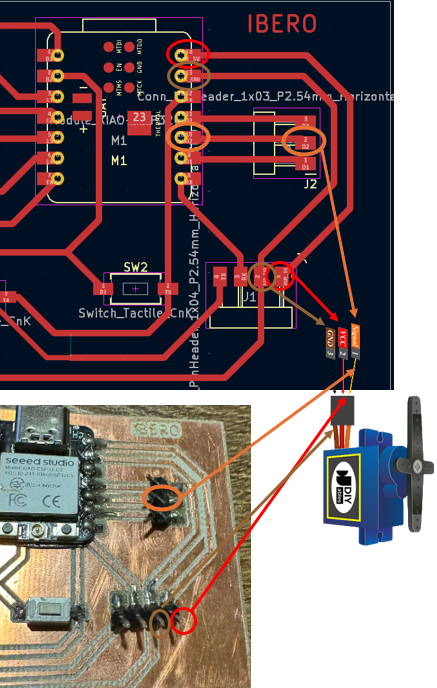
Connecting SG90 Motor to Xiao ESP32-C3
To connect the SG90 motor to a development board like the Xiao ESP32-C3, you first need to power the motor with a 5V source and connect the ground (GND) cable to the board's ground. Then, the control signal cable is connected to a GPIO pin on the board capable of generating PWM signals, as this will be responsible for sending control signals to the servo.
For example, on the Xiao ESP32-C3, you can connect the red cable of the SG90 to the 5V power pin of the board, the brown or black cable to the ground (GND) pin, and the orange or yellow cable to the GPIO pin you want to use to control the servo. Then, you can use a program to generate the necessary PWM pulses to control the servo's position from the ESP32-C3.
Below is the pinout of the xiao to guide us on connections

Recalling a bit from last week's board, we see that the available pins are D6, D7, D8, D9, and D10. Therefore, we will connect it to D9, although it can be any of them since all are GPIO pins. The others will be connected to the 5V and ground pins we left previously.
schedule outputs
I will start with something very simple like moving the servo from 0 to 180 degrees with a delay of 1 second
but before starting we will install the esp32 servo library
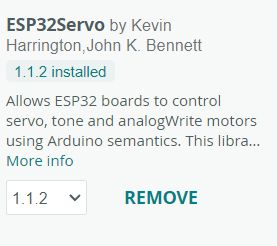
Overview of the ESP32 Servo Library
The ESP32 Servo library is designed to facilitate the control of servo motors in projects using the ESP32 microcontroller. Below are the key features and benefits:
This library is particularly useful for robotics and automation projects where precise and repetitive motion control is crucial.
Explanation
This code will make the servo connected to GPIO pin 9 of the ESP32 move from 0 to 180 degrees in a continuous loop, with a 1-second pause between each movement. Make sure to correctly connect the servo and power it with the appropriate power source.
	  #include <ESP32Servo.h>;  // Include the ESP32Servo.h library for controlling the servo

	  Servo myservo;  // Create an object of type Servo

	  void setup() {
		myservo.attach(9);  // Connect the servo to GPIO pin 9
	  }

	  void loop() {
		// Move the servo to the 0-degree position
		myservo.write(0);  // Set the servo position to 0 degrees
		delay(1000);  // Wait for 1 second

		// Move the servo to the 180-degree position
		myservo.write(180);  // Set the servo position to 180 degrees
		delay(1000);  // Wait for 1 second
	  }
Now that we know how to program a servo and in recent weeks we learned to program LEDs and buttons. let's put that knowledge together and make a code with that knowledge together
The following code will move the servo to position 0 degrees and turn on LED 1 with one button press, pressing button 2 will move it to 90 degrees and turn on LED 2, and finally, pressing both buttons will move it to 180 degrees and turn on LED 3.
Explanation
		#include <ESP32Servo.h>;  // Include the ESP32Servo.h library for controlling the servo

	  Servo myservo;  // Declare a Servo object named myservo

	  #define BUTTON_0_PIN D0 // Define pin D0 for button 0
	  #define BUTTON_1_PIN D1 // Define pin D1 for button 1
	  #define LED_PIN_2 D2     // Define pin D2 for LED 2
	  #define LED_PIN_3 D3     // Define pin D3 for LED 3
	  #define LED_PIN_4 D4     // Define pin D4 for LED 4

	  int button_0_state = 0; // Variable to store the state of button D0
	  int button_1_state = 0; // Variable to store the state of button D1
	  int servo_position = 0;  // Variable to store the current position of the servo

	  void setup() {
		myservo.attach(9);  // Assign the servo control pin (D9)

		pinMode(BUTTON_0_PIN, INPUT_PULLUP); // Configure pin D0 as input with internal pull-up
		pinMode(BUTTON_1_PIN, INPUT_PULLUP); // Configure pin D1 as input with internal pull-up

		pinMode(LED_PIN_2, OUTPUT); // Configure pin D2 for LED 2 as output
		pinMode(LED_PIN_3, OUTPUT); // Configure pin D3 for LED 3 as output
		pinMode(LED_PIN_4, OUTPUT); // Configure pin D4 for LED 4 as output
	  }

		  void loop() {
			// Read the state of button D0
			button_0_state = digitalRead(BUTTON_0_PIN);

			// If button D0 is pressed
			if (button_0_state == LOW) {
			  // Move the servo to the 0-degree position
			  myservo.write(0);
			  digitalWrite(LED_PIN_2, HIGH); // Turn on LED D2
			  servo_position = 0;
			  delay(100);
			  // Short delay to debounce the button
			  while (digitalRead(BUTTON_0_PIN) == LOW) {}
			  // Wait for the button to be released
			  digitalWrite(LED_PIN_2, LOW); // Turn off LED D2
			}

			// Read the state of button D1
			button_1_state = digitalRead(BUTTON_1_PIN);

			// If button D1 is pressed
			if (button_1_state == LOW) {
			  // Move the servo to the 90-degree position
			  myservo.write(90);
			  digitalWrite(LED_PIN_3, HIGH); // Turn on LED D3
			  servo_position = 90;
			  delay(100); // Short delay to debounce the button
			  while (digitalRead(BUTTON_1_PIN) == LOW) {}
			  // Wait for the button to be released
			  digitalWrite(LED_PIN_3, LOW); // Turn off LED D3
			}
		  }

    // If both buttons are not pressed and the servo is not at 180 degrees
    if (button_0_state == HIGH && button_1_state == HIGH && servo_position != 180) {
      // Move the servo to the 180-degree position
      myservo.write(180);
      digitalWrite(LED_PIN_4, HIGH); // Turn on LED D4
      servo_position = 180;
      delay(100); // Short delay to debounce the button
      while (digitalRead(BUTTON_0_PIN) == HIGH && digitalRead(BUTTON_1_PIN) == HIGH) {}
	  // Wait for either button to be pressed
      digitalWrite(LED_PIN_4, LOW); // Turn off LED D4
    }
MG995 Characteristic
Previously the servo worked very well for us but for the final project it could not be used since its maximum load capacity is 2kg so we will use the MG995 motor

| Characteristic | Description |
|---|---|
| Model | MG995 |
| Motor Type | Servo motor |
| Operating Voltage | 4.8V - 7.2V |
| Operating Current | 0.2 - 0.5A |
| No-load Speed | 0.17 sec/60° (4.8V), 0.14 sec/60° (6.0V), 0.12 sec/60° (7.2V) |
| Stall Torque | 10 - 15 kg·cm |
| Weight | 55 g |
| Load Capacity | Approximately 10 to 15 kg·cm (depending on application and conditions) |
| Dimensions | 40.7 x 19.7 x 42.9 mm |
We will use the same previous code but now mounted on the prototype of the dog feeder to observe its behavior
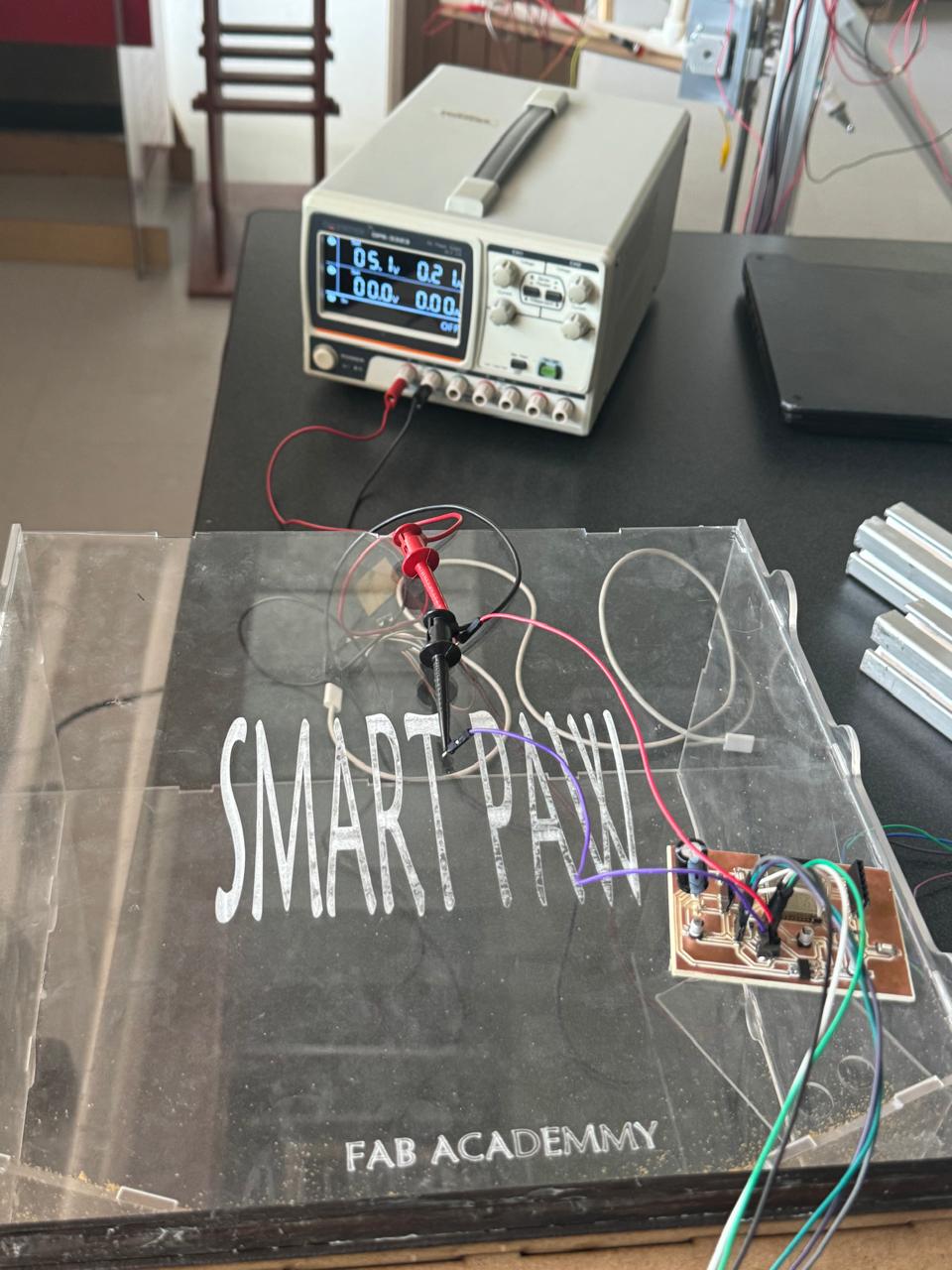
importance of proper supply
In the photo, we can see that the MG995 servomotors are connected to an external power supply set to 5 volts. It is crucial to maintain this voltage because the MG995 is designed to operate at a nominal voltage of 5V, providing a suitable balance between speed and torque. The MG995 operates within a voltage range of 4.8V to 7.2V; operating outside this range can lead to inefficient performance or even damage to the servomotor.
The current measured in the image is 0.21 amperes, which is typical for a servo under light operation. However, under high load conditions, the MG995 can draw up to 1-2 amperes. This current consumption is significant as it indicates the amount of power the servomotor needs to function correctly. The relationship between voltage and amperage is fundamental: voltage provides the necessary "pressure" for the current to flow, while amperage represents the amount of current flow. Maintaining the correct voltage ensures that the servomotor operates efficiently without overheating, and ensuring sufficient current supply prevents malfunctioning and overheating of the servomotor.
Using an external power supply is important because the USB ports on a computer cannot supply sufficient current for a servomotor under high load. USB 2.0 ports provide a maximum of 500mA (0.5A), and USB 3.0 ports up to 900mA (0.9A), which is not enough to power multiple servomotors or a servomotor under high load. Additionally, connecting servomotors directly to the computer can overload the USB ports, potentially damaging the computer's motherboard or the USB ports themselves.

An external power supply ensures that a stable voltage and sufficient current are provided for the servomotor's needs. External power supplies are designed to handle higher current demands, which is essential for the proper functioning of servomotors like the MG995. Moreover, these power supplies often have built-in protections against overcurrent, overvoltage, and short circuits, enhancing the reliability and safety of the system. Keeping these parameters within recommended limits avoids damage and ensures optimal performance of the MG995 servomotor. The importance of amperage lies in the fact that if the servomotor does not receive enough current, it will not be able to deliver the necessary power to move the load, which can cause the motor to stall or operate intermittently.
On the other hand, if the current supplied exceeds the servomotor's capacity, it can overheat and suffer damage. Therefore, it is always recommended to use a power supply that can provide adequate and stable amperage for the servomotor in all operating conditions. Correct voltage and current are essential for optimal performance, longevity, and reliability of a servo. Incorrect levels can lead to overheating, damage, erratic behavior, and reduced lifespan, compromising system effectiveness and safety.