11. Input devices
Research
In the realm of computing and technology, an "input" refers to any type of information, data, or signal that enters into a system, program, or electronic device. Inputs are fundamental for computer systems to interact with the environment and process information appropriately. These inputs can come from a wide variety of sources, such as keyboards, mice, microphones, sensors, scanners, among other input devices. The quality and accuracy of inputs directly influence the effectiveness and performance of computer systems, as they constitute the raw material for executing operations and making decisions.
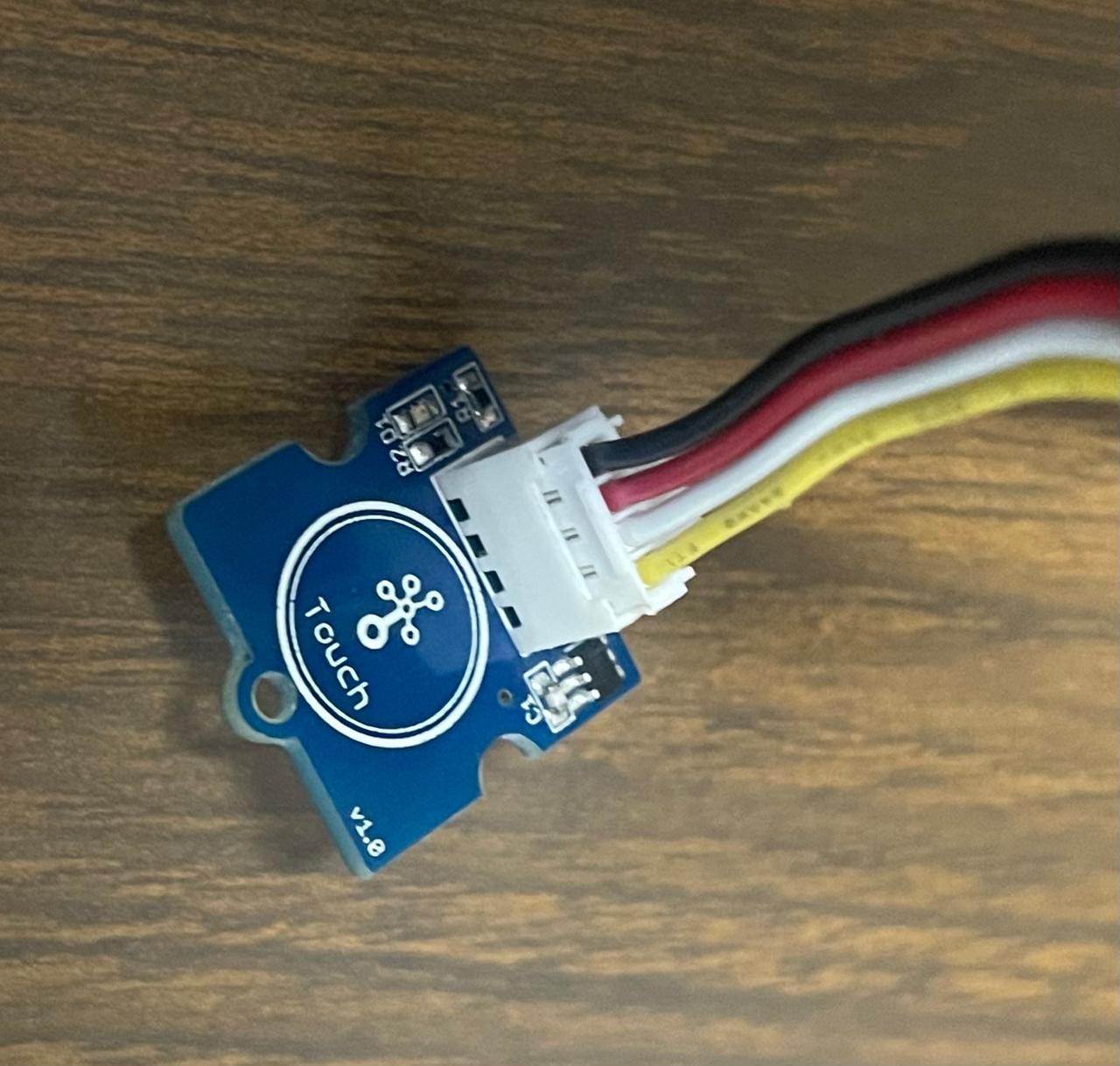
A touch sensor button, also known as a touch-sensitive button or touchpad, is a type of input device that detects physical touch or pressure to initiate a specific action or command. Unlike traditional mechanical buttons, which require physical depression, touch sensor buttons respond to gentle taps or swipes, providing a more intuitive and user-friendly interface.
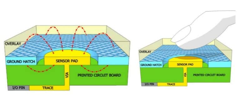
In the previous image, you can see an exploded view of a simple touch sensor button. The overlay sits on top. It serves as a separation between the PCB and the user. The thickness of the overlay affects the touch performance. The sensor pad is the crucial element, which is a solid copper pad. If the buttons are smaller, touch sensitivity decreases. If the buttons are too large, they become overly sensitive. The mesh pattern is the ground. The electric field from the sensor pad emerges and terminates at ground. When the button is touched, an alternative path for field lines is provided. This, in turn, reflects an increase in capacitance. The touch controller detects this change in capacitance. To obtain more information about the Grove - Touch Sensor, you can view its datasheet.
The capacitive touch sensor operates based on the principle of capacitance. When a conductive object, such as a human finger, approaches or touches the surface of the sensor, it alters the electrostatic field of the sensor. This alteration is detected and measured as a change in capacitance. The microcontroller or the sensor's detection circuit interprets this change and translates it into an input signal that can be used to activate or deactivate a specific function in the device.
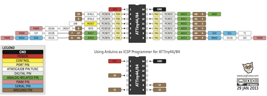
To operate the touch button for the physical connection, the part called SIG should be connected to pin B2 of the Attiny44, which is marked as 8 in the programming. The other two wires needed are VCC and GND. It is important to mention that for the button, the operating voltage is 2.0 - 5.5V. The Attiny44 operates at a voltage range between 2.7V and 5.5V.
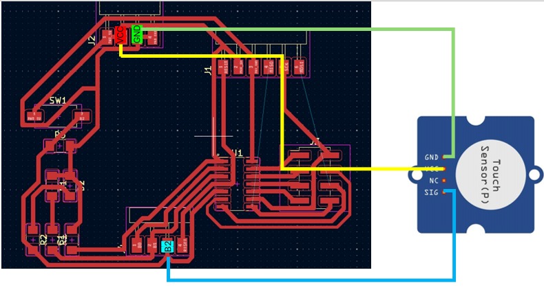
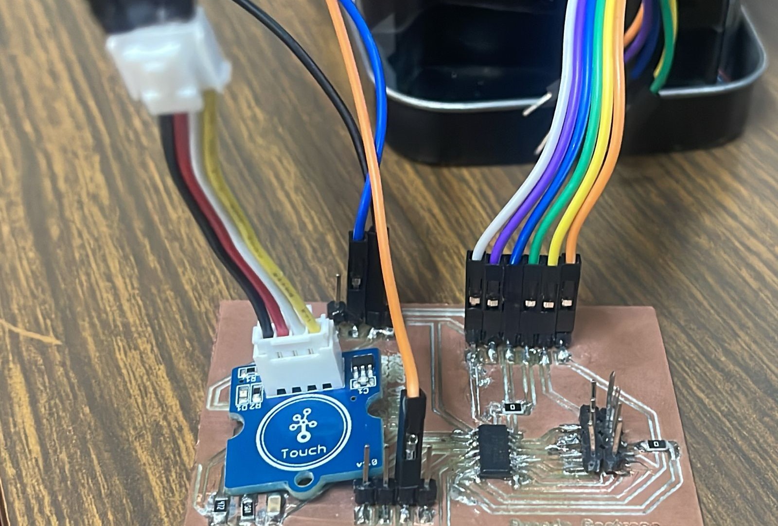
I used my PCB from my week 8 as yo can see in my last picture.
Here you will find the group assignment with a little more information about the inputs.
Programming
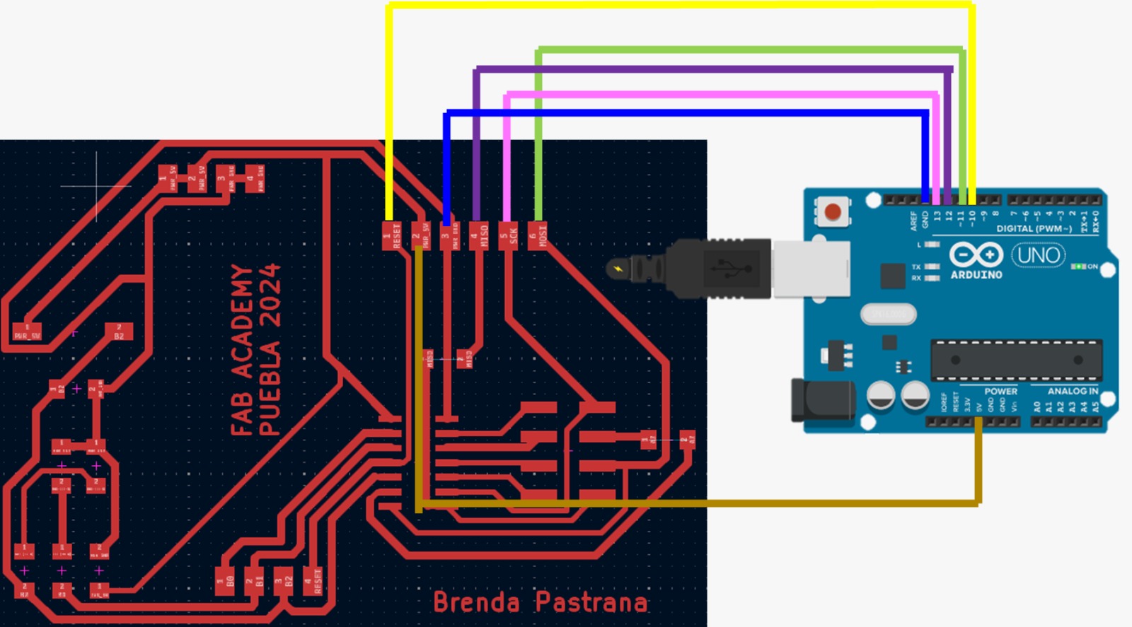
The same as the outputs week, I used an Arduino UNO as a programmer and its software.
Because initially I couldn't get the LED to turn on with the code, I decided to implement serial communication to check if the code was working correctly. After confirming that it was indeed working, I realized that I had used the wrong pin in the programming.
Video
Problems
This week actually felt very similar to the outputs week, although the only difference and issue I encountered is that, because I found it interesting to discover how this sensor worked and I had never used it before, I needed to know how to connect it or if I needed to place a resistor. However, after doing a bit more research and with the documentation from this week, I learned how to obtain its value, but other than that, I didn't have any major issues.
Conclusion
During this week, I learned to work with capacitive touch sensors, which allowed me to better understand how these devices can be integrated into electronic systems to improve user-device interaction. The main difficulty I faced was calibrating the sensor to respond adequately to touch, but in the end, I managed to adjust the sensitivity parameters correctly. Additionally, it is important to understand that input sensors are those that return a value from the outside to the microcontroller so that it can work with that information.