9. Output devices
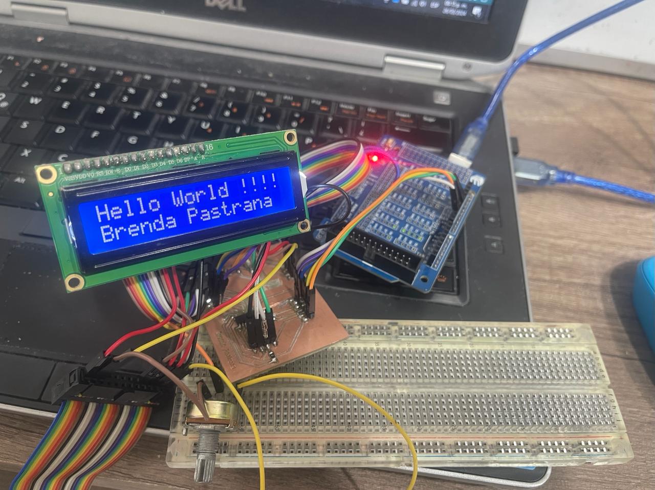
This week I worked on output devices. I used the PCB I made in week 8. For this occasion, I chose to use a 16x2 LCD, although initially, I tried with a speaker, but it seems that was not the most optimal choice.
Here you will find the group assignment with a little more information.
Research
16x2 LCD displays are connected to microcontrollers or embedded systems using various pins, including RS (Register Select) for selecting between data and commands, RW (Read/Write) to indicate whether reading or writing to the display, EN (Enable) to enable communication, and pins D4 to D7 to transmit data on a 4-bit or 8-bit data bus. These connections allow for precise and efficient control of the display and transmission of information for visualization. In terms of power consumption, 16x2 LCD displays typically require between 1 and 2 watts, depending on the backlighting technology used and the configured brightness.
A potentiometer will be connected to my PCB and will take the reading to send it to the LCD in order to adjust the brightness. This adjustment is necessary because the backlight intensity and screen contrast may vary depending on environmental conditions and device settings. By adjusting the potentiometer, the voltage applied to the screen can be modified, allowing for finding the optimal contrast level for clear and legible text display under different lighting conditions.
What I learned from interfacing output divices
As I mentioned, I used my PCB from my week 8.
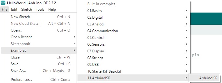
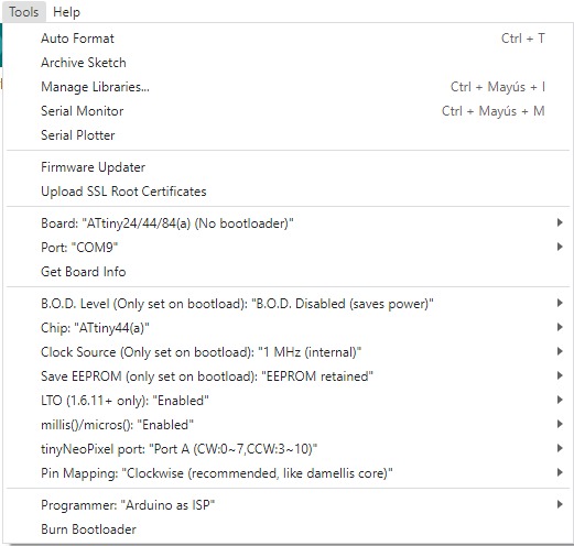
To use the Arduino as a programmer, you need to upload the following code, which can be found under Files -> Examples -> 11.ArduinoISP -> ArduinoISP. Once you've loaded it, if your ATTINY44 is new, you need to set the following characteristics and make sure to select the bottom option that says Burn Bootloader.

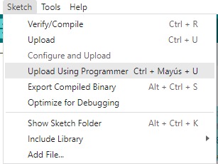
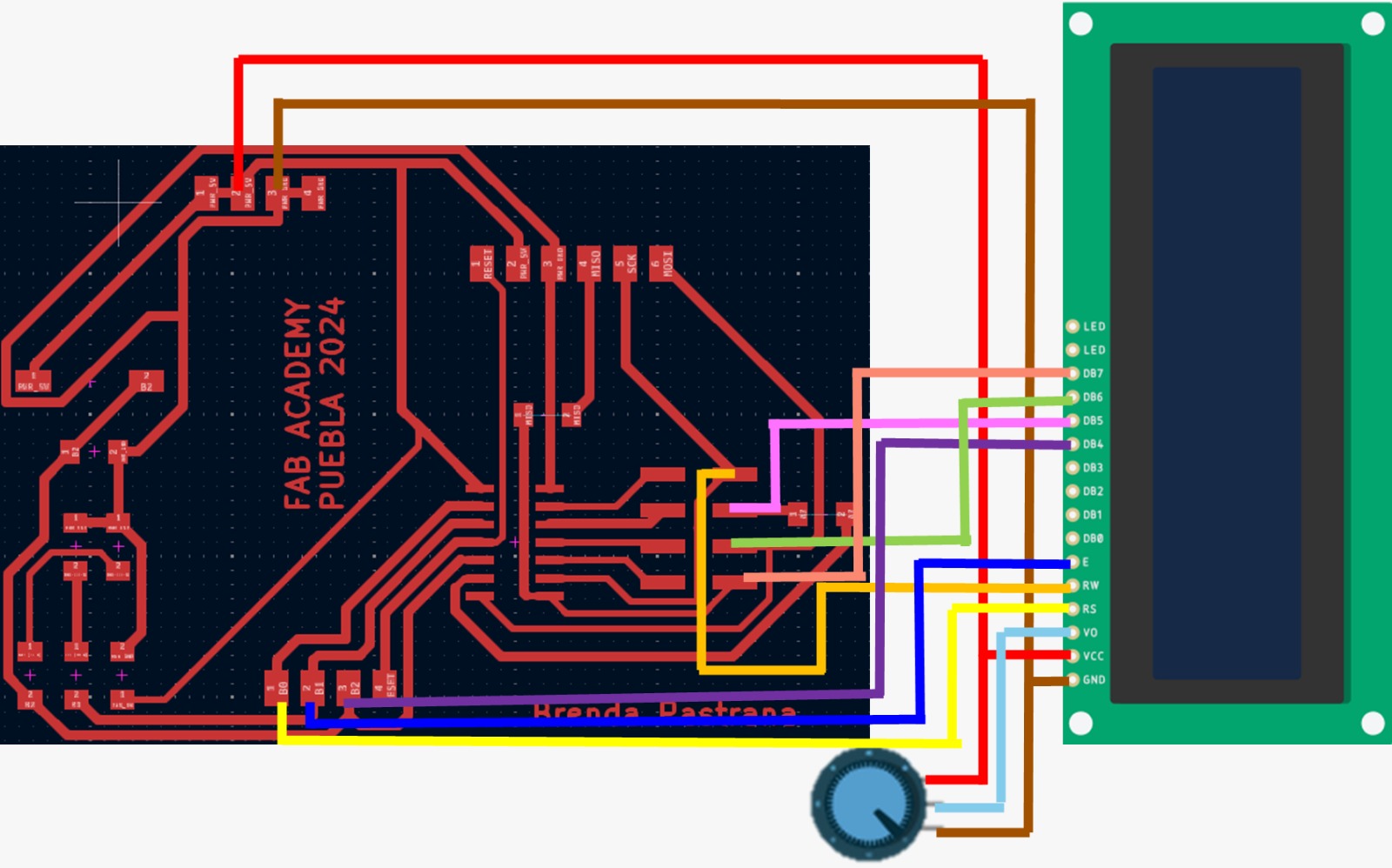
After that, you will be able to upload the desired code by making the connections shown in the PCB diagram with the Arduino UNO. However, it is important to upload the program from the Sketch -> Upload Using Programmer menu.

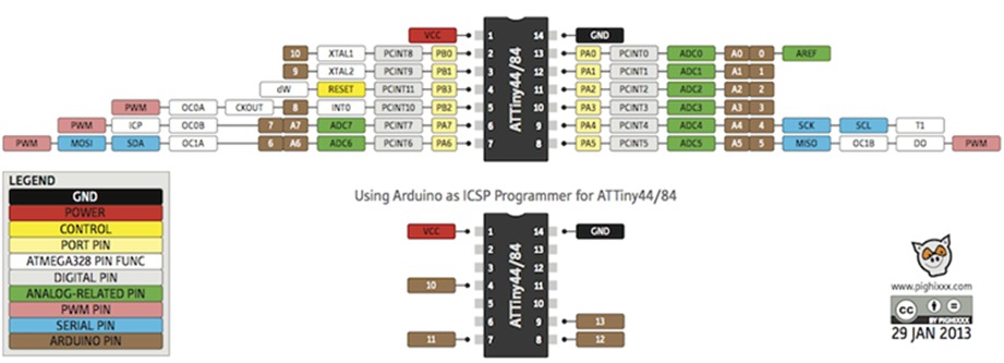
Necessary connections for the LCD to the PCB of the ATTINY44. For the physical connections, I used pins 10, 9, 8, 7, 6, 5, and 4, as well as VCC and GND.
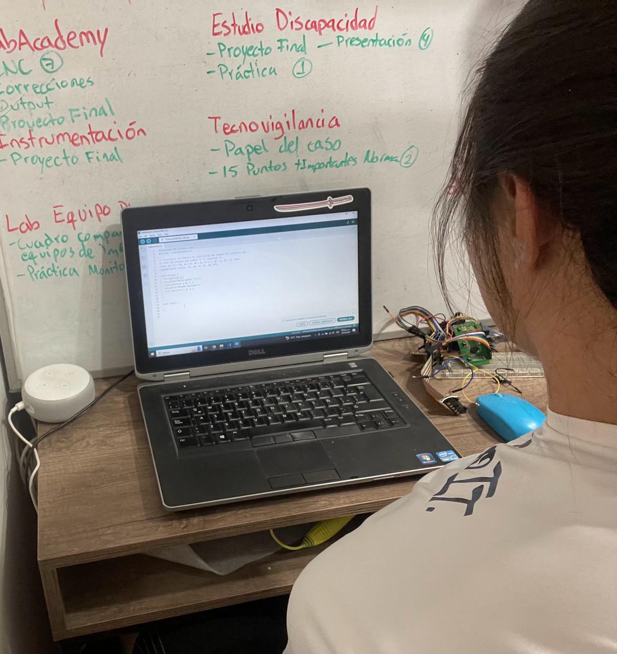
Here is the program I used to make the LCD work.
For this week, I used:
- 2 resistors 0 ohms
- PCB Attiny 44
- 16x2 LCD screen
- Potentiometer
- 220 Ohm resistor
This week I faced complications; I spent the entire day trying to figure out why it wasn't working. I thought it was due to my connections, even changing the pins I connected the LCD to about 5 times, but it still didn't work. The screen would only display brightness without showing any letters, even though I had a potentiometer. Additionally, I realized that I hadn't connected enough voltage and ground pins.
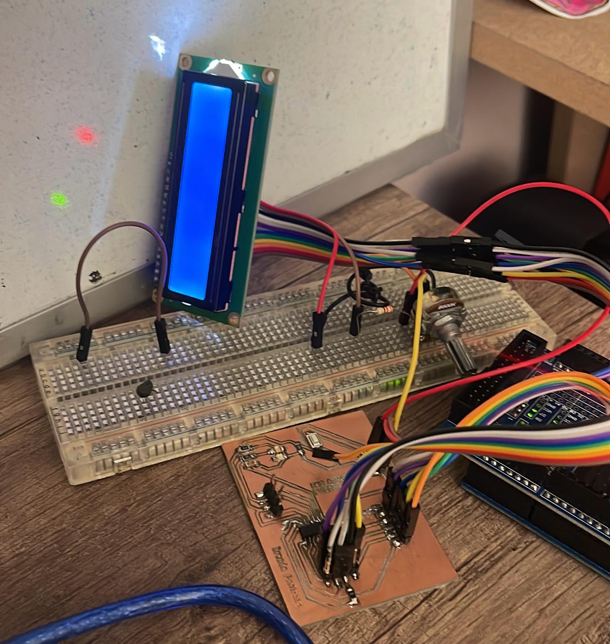
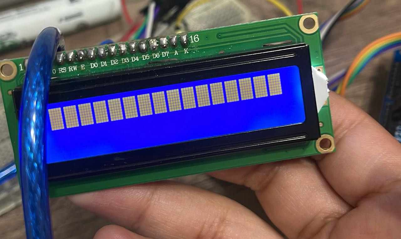
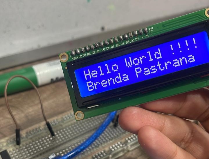
Later on, I realized that I had forgotten to connect the RW pin of the LCD. Although I highly doubted that was the issue because some internet pages mentioned it was optional and could be connected to power, I went from having a screen with only boxes to one displaying letters. Therefore, I highly recommend not getting frustrated when things don't work out and continuing to investigate.
On the other hand, the first option I had was to work with a speaker, and I thought it would be the same as using a buzzer but with a transistor to amplify the sound. However, although it did emit sound, it wasn't what I expected. I have the theory that what wasn't working properly was the speaker because I was powering it with a square 9V battery, but it still didn't sound good. The song I wanted to play was the Imperial March from Star Wars.
The transistor I was using was the BC547B, which is an NPN transistor suitable for use in audio amplifier input and output stages. However, this might have been the mistake as it could have been the wrong transistor for the job.
In the following link, you can find the program I tried to use and more information.
Conclusion
In conclusion, I learned how to design and manufacture a printed circuit board (PCB), which allowed me to develop skills in using design software and soldering electronic components, as well as programming different outputs and understanding how not to do it. In the group assignment, we created a functional electronic system, highlighting the importance of collaboration and integrating various skills to ensure all system components worked correctly.
