13. Networking and communications
The task for this week is to design, build and connect nodes, to achieve this im using previous boards: the One from week4 with a xiao RP2040, the second is from week8 with an attiny44a-ssu and the most recent built in week11 that will work as a master to handle the other two.
In the group assigment we linked separate projects.
Types of wired Communication
Asyncronous SERIAL/UART (rx[receiver] and tx[transmitter])
Simple, allows data to flow in only one direction—either from the sender to the receiver or vice versa, Data is sent as binary pulses, where a logic HIGH may represent 5 Volts and a logic LOW represents 0 Volts.
The transmiter (tx) send to the receiver (rx) of the other microcontroller.
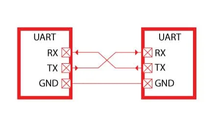
Src: Microcontroller labs
SPI (mosi[main Out secondary In], miso[main In secondary Out], sck[Serial Clock], ss[secondary Select] or reset)
SPI operates in a master-slave setup, where the master device initiates the communication and provides the clock signal (SCK), A single master can communicate with multiple slaves using separate slave select lines.
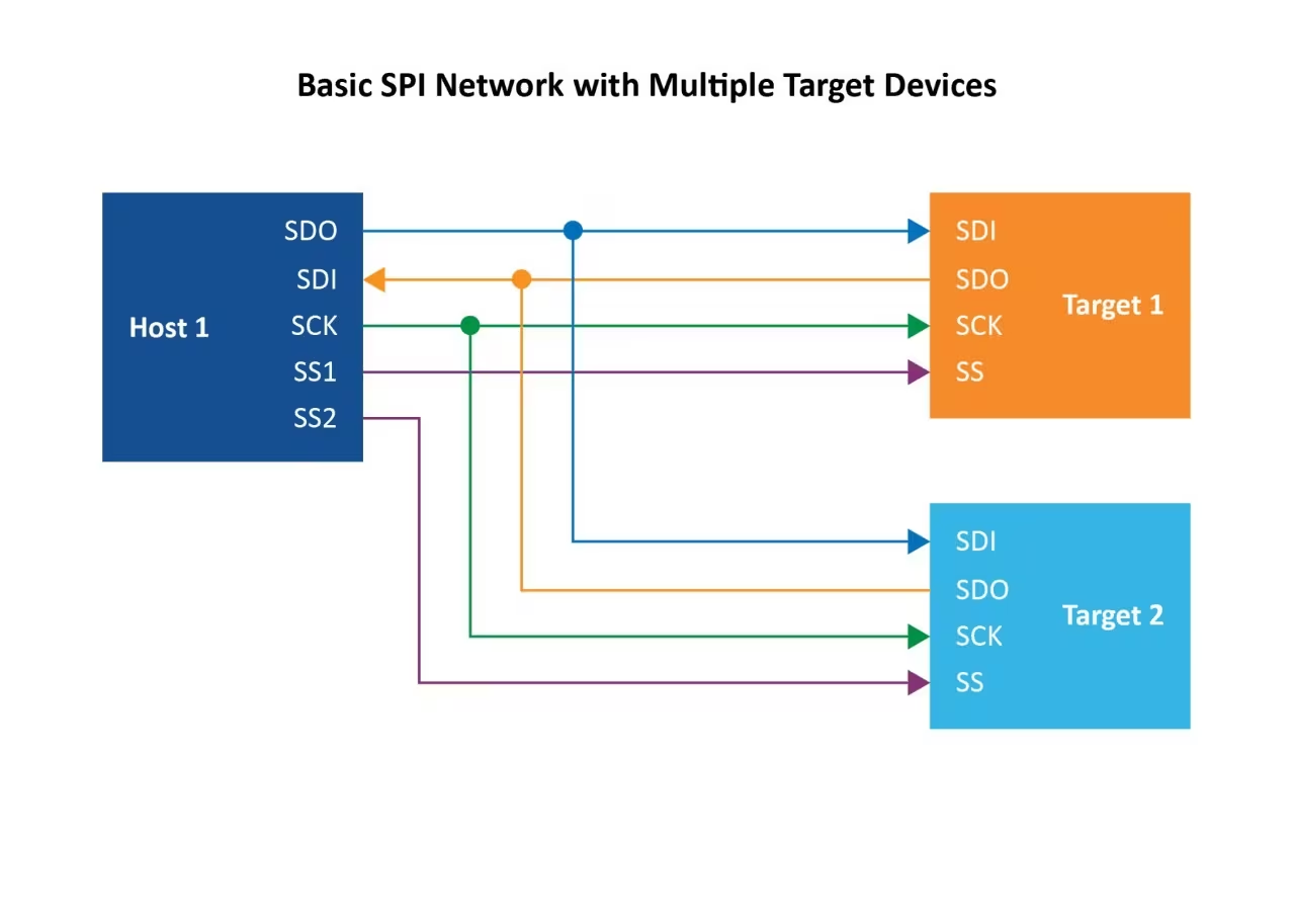
Src: Microchip Technology
I2C (sda[Serial Clock Line], scl[Serial Data Line])
I2C supports Master and slaves chains, allowing complex communication scenarios, Devices on the I2C bus are addressed using either 7-bit or 10-bit addresses. Communication happens in messages that are broken into frames, with each frame containing an address and one or more data bytes, using pull up resistors is recommended to avoid, data losses and more physical range between Devices.
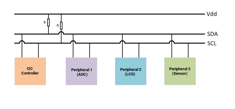
Src: Mathworks
Special types of wired Communication
I2S
I2S is designed specifically for high-quality audio data transfer between devices like DACs and ADCs. It uses a shared clock signal to synchronize the transmission of audio data, The protocol separates the left and right audio channels using a word select line if stereo.

Src: Wikipedia
I3C
I3C is an enhancement over I2C, offering higher data rates and features like in-band interrupts and hot-join capabilities. Dynamic Addressing: Unlike I2C’s static addressing to prevent address collisions, it requires 2 masters and you can generate backward compatibility with I2C.
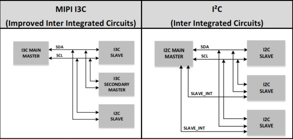
Src: Total phase
My communication protocol
for this week I have decided to use the I2C communication method since the simple UART is not recommended for three devices and the SPI is the one that I regularly use to program the attiny, the advantage of I2 C is that you can put several devices as long as they do not have the same address and that you do not overload the channel, in addition to that you must have a couple of pull up resistors to ensure the packages can travel through the 'river'.
One of the first questions that came to my mind was whether communication could be carried out if the devices had different logical voltage values, XIao(3.3V) and attiny (5V)?
-
as I did not make much sense in my search I found that this type of adapters were very busy, after informing me I saw 2 things, that are used in gpio pins not in normal communication and that are usually used to control RGB leds strips of any type since they require a higher voltage.
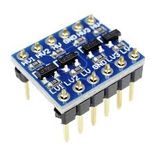
then the answer to the question is yes as long as the master is a Xiao since this will reduce the height of the waves but, the attiny44a can still work at those voltages.
The objective
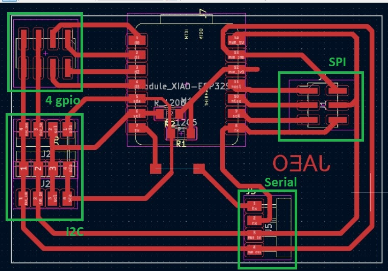
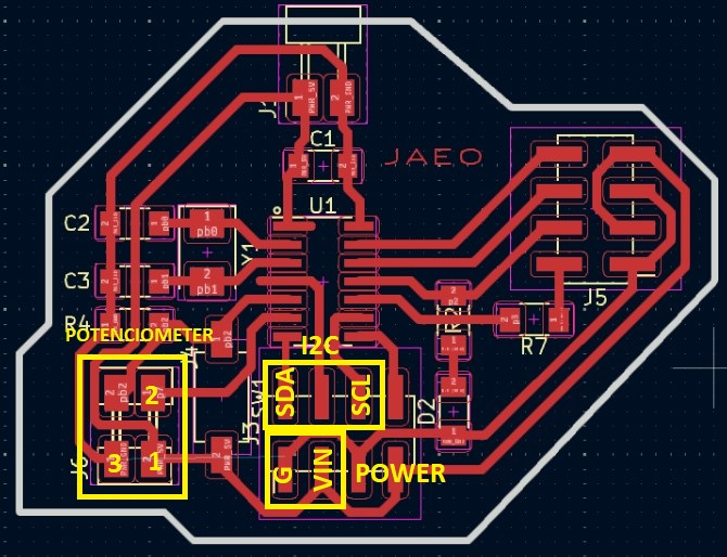
Now: the connections to my previously fabricated boards
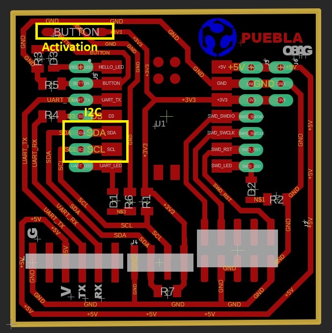
-
Xiao Master
Required:
The board
Two female to female dupoint wires
-
Xiao Slave
Required:
The board
2 male-female dupoint wires for power source
A small servo
-
attiny44a Slave
Required:
The board
7 dupoint female to female wires
A potenciometer
Coding
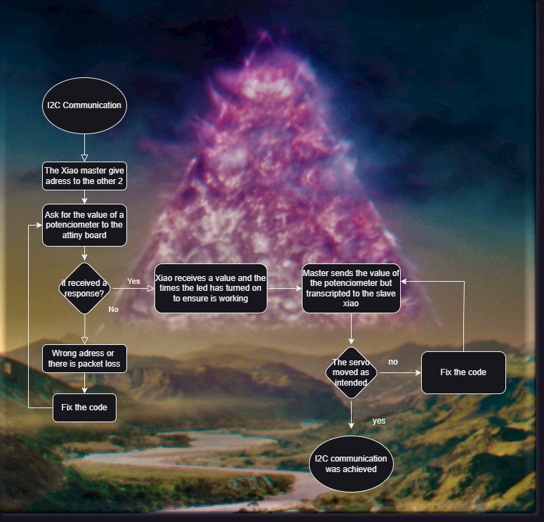
We need to code each board individually, following the previous diagram to make it easier, the key points:
Assign adresses and pins for each
Attiny reads the value of its potenciometer, master ask and start blinking its led
Master processes the data
Master send the value and you can see the slave decrypting in a correct movement
Mistakes are learning
I prefer to put the errors here at the beginning as they are important factors at the time of any communication I would say.
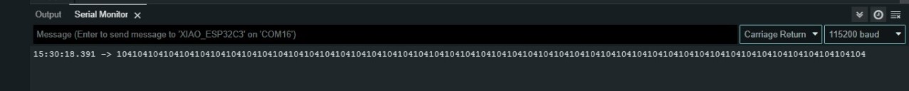
The many request little time error
This error is produced by a continue request of the master without closing and openning the channel as needed, you can see error values because the slave doesn't achieve to send a complete value.
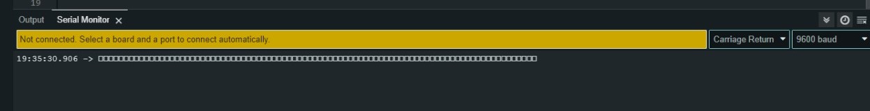
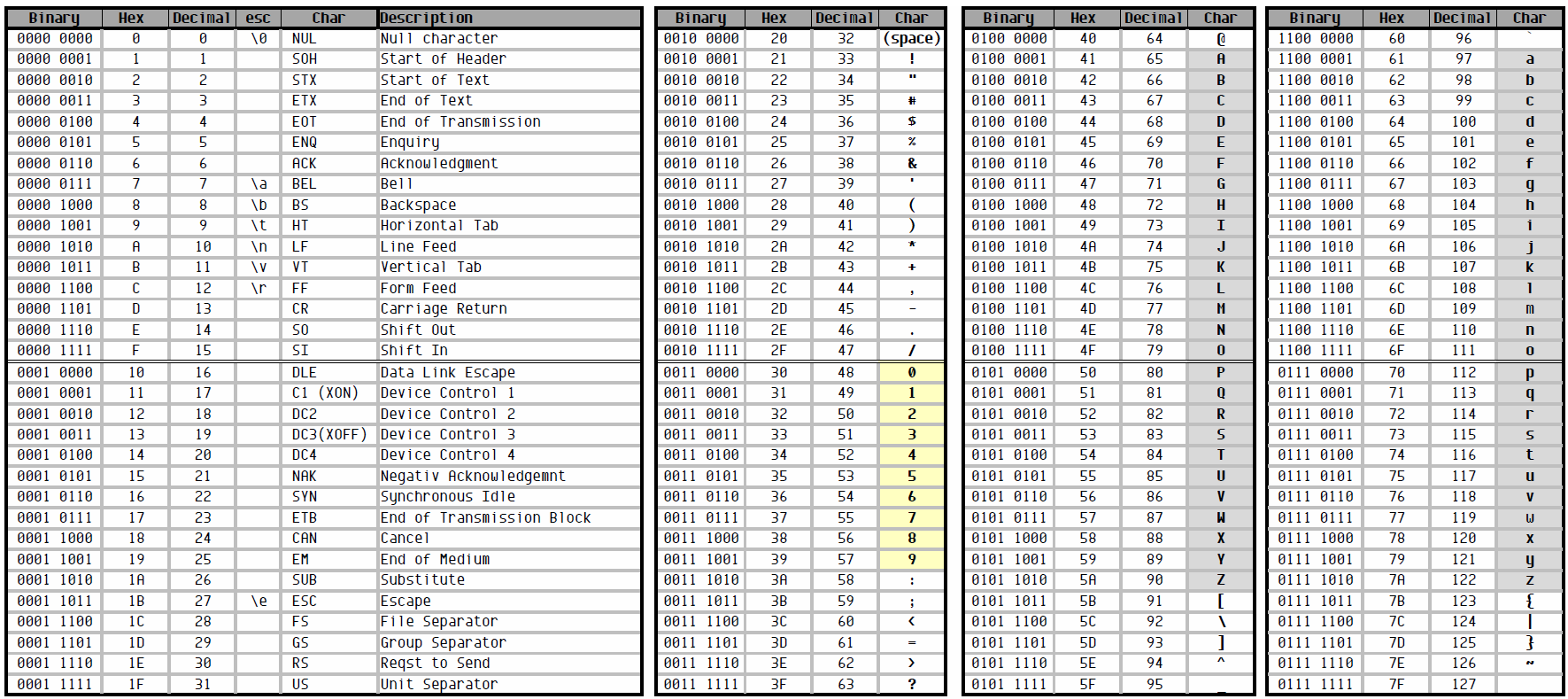
The data type error
This not exactly an error, what is actually happening is that the simplified methods of arduino are decoding what could be a "word" in the different values of the ascii code, this because the communication is carried out by sending bytes (8 bits 1/0), and the Arduino methods like char or int can come to unintended translations.
Part 1 Assign adresses and pins for each
Master
#include "Wire.h" //I2C library
//Xiao adress will be 0x8B
//Attiny adress will be 0x4A

#define button D1 //to breakdown the processes
#define led D7
const int info = 5; //amount of data we need
int ledtimes = 0;
int val = 0;
bool butstate = 0;

void setup() {
  Wire.begin();       //Start the channel in SDA-SCL
  Serial.begin(9600);
  pinMode(button,INPUT);
  pinMode(led,OUTPUT);
  Serial.println("I2C communication");
}
Attiny
#include "Wire.h"

#define potenciometer A7
int val = 0;

void setup() {
  Wire.begin(0x4A);                // join i2c bus with address #0x4A
  pinMode(potenciometer,INPUT);
  Wire.onRequest(requestEvent); // register event when master ask him for info
}
Xiao
#include "Wire.h"
#include "ESP32Servo.h"

Servo myservo;

int pos = 0;

void setup() {
  myservo.attach(D0);
  Wire.begin(0x8B);                // join i2c bus with address #8
  Wire.onReceive(receiveEvent);    // Master sends him information
}
Part 2 Attiny reads the value of its potenciometer, master ask and start blinking its led
Master
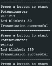
 Serial.println("------------------------");
  Serial.println("Press a button to start");
  while (!butstate){ //Blink while waiting for the button to be pushed
    butstate = digitalRead(button);
    digitalWrite(led,HIGH);
    delay(100);
    butstate = digitalRead(button);
    digitalWrite(led,LOW);
    delay(100);
    ledtimes ++;
  }
  butstate = 0;
  Serial.println("Potenciometer");
  Wire.requestFrom(0x4A, info); //Attiny, amount of information
  for(int i=0;i<4;i++)
  {
    char d1 = Wire.read(); //receive byte as char
    Serial.print(d1);
  }
  int c = Wire.read(); // receive a byte as number
  val = c;
  Serial.println(c);
  Serial.print("Led blinked: ");
  Serial.println(ledtimes);
  delay(500);
Attiny
void loop() {
  delay(100);
}

void requestEvent() { //function run when master ask for 0xA4 for information
  val = analogRead(potenciometer);
  Wire.write("val:");
  Wire.write(val);
}
Part 3 Master processes the data
Master
void encrypt(int x){
  char data = 'X';
  if (x < 40) {
  data = 'B';
  } else if (x < 80){
  data = 'C';
  } else if (x < 120){
  data = 'D';
  } else if (x < 160){
  data = 'E';
  } else if (x < 200){
  data = 'F';
  } else{
  data = 'A';
  }
}
Part 4 Master send the value and you can see the slave decrypting in a correct movement
Master
encrypt(val); //Call of the function

//We add the send event to the function
Wire.beginTransmission(0x8B);
Wire.write(data);             // Send the byte
byte error = Wire.endTransmission();

//Huge I2C function to realize if the communication worked or why it failed
if (error == 0) {
  Serial.println("Transmission successful");
} else {
  Serial.print("Error: ");
  Serial.println(error);
}
Xiao
void loop() {
  delay(100);
}

void receiveEvent(int howMany){
//The wire.available builtin function count the data send and every
//time you read a byte reduces the count by one
   while (Wire.available()) {
    char c = Wire.read(); // Receive a byte
    decrypt(c); // Decrypt received byte and control servo
  }
}

//function to move the servo
void moveServo(int targetPosition) {
  if (pos < targetPosition) {
    for (pos = currentPos; pos <= targetPosition; pos++) {
      myservo.write(pos);
      delay(15);
    }
  } else {
    for (pos = currentPos; pos >= targetPosition; pos--) {
      myservo.write(pos);
      delay(15);
    }
  }
}
//Funtion to translate using switch case for better looking than a if else chain
void decrypt(char var) {
  switch (var) {
    case 'A':
      moveServo(0);
      break;
    case 'B':
      moveServo(30);
      break;
    case 'C':
      moveServo(60);
      break;
    case 'D':
      moveServo(120);
      break;
    case 'E':
      moveServo(150);
      break;
    case 'F':
      moveServo(180);
      break;
// Similar to else
    default:
      moveServo(90);
      break;
  }
}
Hero Shoot
Final Codes:
The final code for the Xiao Esp32c3 master: XiaoMaster.ino.
The final code for the attiny44a-ssu slave: AttinySlave.ino.
The final code for the Xiao RP2040 slave: XiaoSlave.ino.
Final reflection
During this week I learned a lot about the different types of data and how two devices communicate, where there are 4 roles: someone asking for information, someone waiting to be sent, someone who commands when asked and someone who doesn't need to be asked; why and when you need some pull up resistors in your SDA-SCL pins.